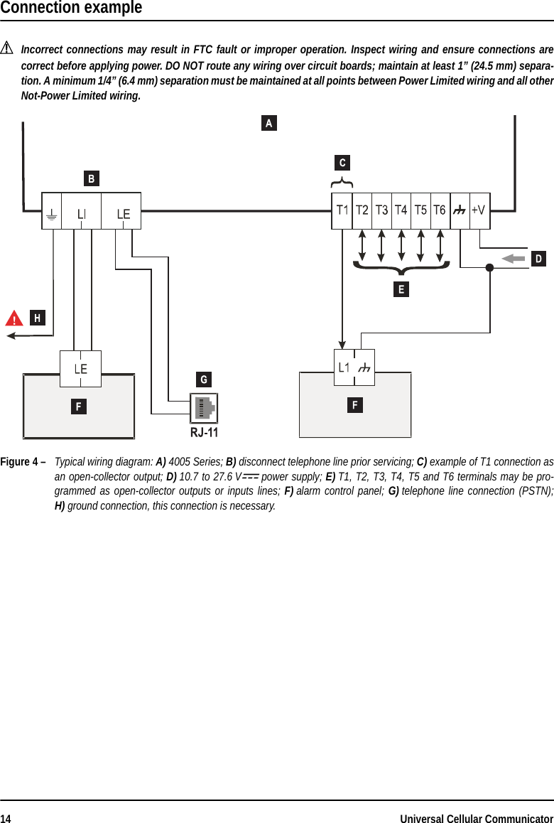
Tyco Safety Canada 163G4005 3G Cellular Alarm Communicator User Manual istisd2eGS4005 0 0
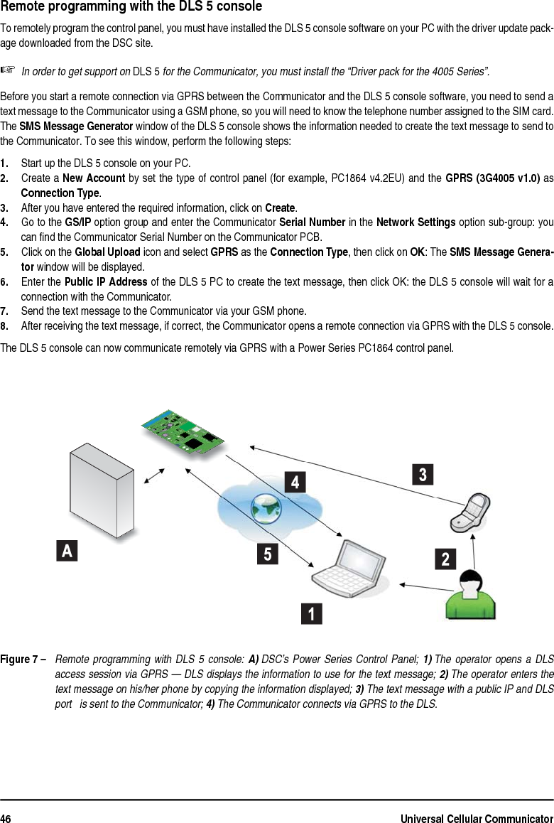
Digital Security Controls Ltd. 3G Cellular Alarm Communicator istisd2eGS4005 0 0
UserManual.wiki
>
Tyco Safety Canada
>
163G4005 User Manual
User Manual
Navigation menu
Upload a User Manual
Namespaces
Wiki Guide
HTML
PDF
Info
Views
User Manual
Discussion / Help
Navigation

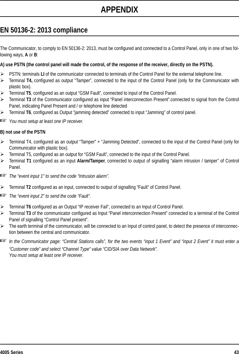
![4005 Series 7Jumpers DescriptionSee Figure 2 on page 3.Jumper 21j pins 1 and 2 connected, no input current limit (default);k pins 2 and 3 connected, input current limit (450 mA, from battery charger side).PST (Pass-Through)J open, Pass-Through disabled (default);K closed, the communicator will be able to perform remote programming of the PC 1864 4.1 EU, PC 1864 4.2 EU, PC 1864 4.2ADT Spain and PC 1864 4.5 ADT Spain DSC Power Series intrusion panels, via cellular and PC-Link.USBThe communicator, according to the jumper setting, from the USB point of view may be Host or Device:J open, Device role (default);K closed, Host role (see page 15).TMP (Tamper):J open, tamper detected (default);K closed, tamper not detected.UFCFuture UseGeneral descriptionThis Communicator manages SMS and Central Station transmissions and can simulate the land line in the event of trouble (landline down) or even substitute the land line completely in areas where the GSM service is provided and where the land line is notavailable. It has capability of communicating alarm signals via the GPRS data network. This capability enables a fast reliable pathto central stations equipped with a Sur-Gard System III or System II receiver.The performance of this Communicator depends greatly on GSM Network coverage, therefore, it should not be mounted withoutfirst performing placement tests of the antenna to determine the best location for reception (at least the LED should remain lit).The communicator has 6 T terminals that can be programmed as follows:– Outputs (default setting) which can be activated/deactivated remotely, or used to provide status indications (problems on thePSTN telephone line; problems on the GSM network; Supervision Message Missing; Fail To Communicate FTC), IP receiver fault,Power fault, Tampers, Jamming detect, Antenna fault, Reserved output.– Input: Panel interconnection Presence: used to be connected with a panel, Voice dialler: used to trigger a voice dialler event, SMSdialler: used to trigger a SMS dialler event, Dialler Block: used to stop the dialler and delete the queue, Force Communication OnGSM: force the line switch from LE to LI, Internal CID/SIA: used to generate the internal CID/SIA event. This Communicator canactivate only as intended and cannot be used as a modem for fax/data transmissions or for teleservice operations.Parts Identification The numbers in square brackets [ ] in this manual refer to the main parts of this Communicator (see Figure 1 and 2, and relativetable on page 2).](https://usermanual.wiki/Tyco-Safety-Canada/163G4005/User-Guide-2899073-Page-7.png)
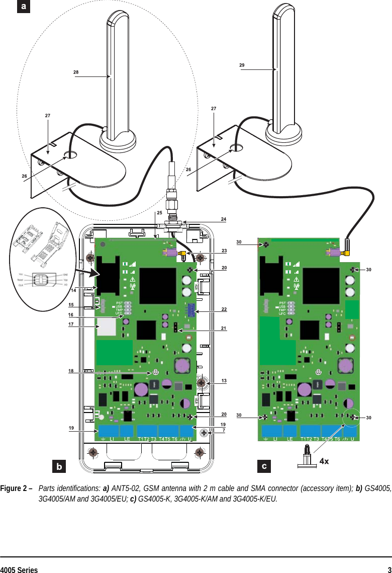
![8Universal Cellular CommunicatorGS4005-K, 3G4005-K/AM and 3G4005-K/EU mountingThis Communicator shall be installed by qualified SERVICE PERSONS only, in the shelter of a safe and dry site, away from radio-transmitting equipment.Test the GSM Network reception before mounting this Communicator in the proposed placement.Do not route any wiring over circuit boards.The length of the power cables cannot exceed 3 meters.This Communicator consists of a board intended to be placed inside the intrusion panel, preferably having a metal cabinet, and of anantenna that is connected to the board by a coaxial cable. During normal working, those elements (board, antenna and cable) couldgenerate radiated electromagnetic fields and, if there are any electronic devices not sufficiently immune to such fields nearby, theremight occur certain unwanted interactions. For this reason it is advised to place the board as far away as possible from such susceptibledevices and to put the antenna on the external surface of the metal cabinet or far away from it by means of the bracket. It is advisedto keep inside of the panel metal cabinet the minimum coaxial cable part and to place any extra length on the outside of the metal box.1. Loosen the screws and remove the control panel cover. 2. Establish an area inside the metal casing which can be used to hold the board, including the wiring.3. Position the 4 adhesive plastic supports on the base of the metal base, then fit the holes [30] on the Electronic board into theadhesive plastic supports, as illustrated in Figure 3. 4. Fix the antenna with the 2 m cable [29] above the metal cabinet (Figure 3) in such manner that the magnetic base will be con-joint with the surface. Feed the antenna cable through the cable feed opening in the metal cabinet.It is possible to use the metal support [27], see Figure 2. Fix the metal support [27] by using the holes [26] on an adequateprop. Fix the antenna with the 2 m cable above the metal support [27] (Figure 3), in such manner that the magnetic base willbe conjoint with the surface. Pass the antenna lead through the hole [26] in the metal support [27].5. Connect the cable to the GSM antenna connector [23].6. Complete the connections on the terminal boards [19].7. Close the jumper TMP to disable the tamper detection.8. Insert the SIM-CARD face down in the SIM holder [14] (see Figure 2).The SIM-CARD PIN must be disabled before the card is inserted into the Communicator.It is recommended that you disable call forwarding on your SIM card.9. Make sure that the Line Status (Yellow) and System Fault (Red) LEDs flash when the Communicator is switched on: thisindicates that the Communicator is in its start-up phase.10. Check signal strength:make sure that at least the LED remains lit; the LED lit indicates optimal coverage;if the LEDs and are OFF, the signal strength is TOO WEAK: for the signal to be of an acceptable level, at least theLED must be lit.11. Close the cover of the control panel on the base using the suitable screws.Connect power circuit and the telephone line only after the cabinet has been secured to the wall or structure and has beenconnected to the protective earth ground of the building.Before inserting or removing the SIM card, please ensure the device is powered down.ANT5-15 Remote Antenna For details of how to fit the remote ANT5-15 outdoor antenna (15 m cable length with adapter) please refer to the instructions sup-plied with the product. The ANT5-15 is used to provide the Communicator a excellent GSM signal strength (see Figure 3).](https://usermanual.wiki/Tyco-Safety-Canada/163G4005/User-Guide-2899073-Page-8.png)
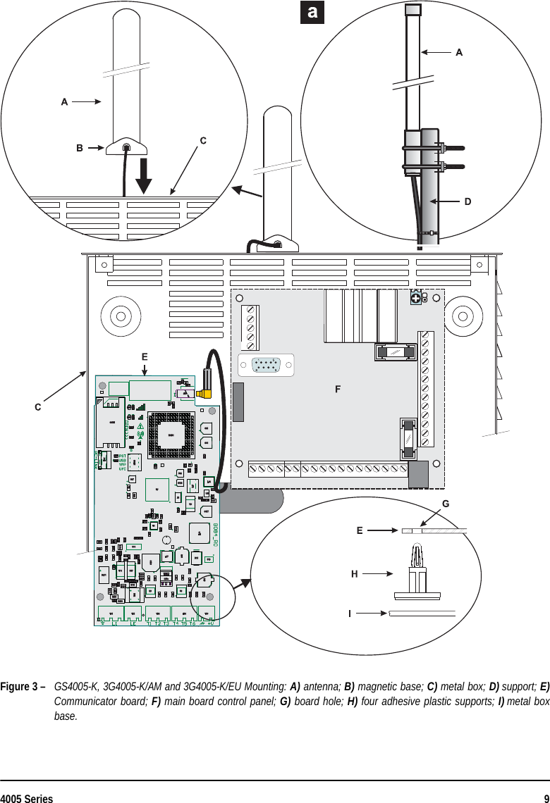
![10 Universal Cellular CommunicatorGS4005, 3G4005/AM and 3G4005/EU mountingSee Figures 1 and 2.1. Mark the position of the holes [8] required to fix the plastic base [2] and the antitamper device [13] to the wall.2. Drill holes in the wall as marked.!Make sure you do not damage wiring or pipes in the chase.3. Insert the 5 supports into the holes on the wall.4. Feed the connection cables through the opening on the base. 5. Fix the plastic base to the wall using wall anchors (not supplied).6. Insert the silicon carbon pills for antitamper on the dedicated support on the base [12].7. Insert the back-up battery (accessory item).8. Place the electronic board on the supports [20] and push it down until it clicks into place.Read the following steps (9, 10 and 11) if the signal with the integrated antenna is low, to mount the ANT5-02 external optionalantenna, else go to step 12.9. Connect the antenna cable [23] to the connector on the electronic board and fix other connector of the cable to the communi-cator backplate with the nut and washer [24] (into dedicated hole).10. Connect the magnetic antenna cable, using the SMA connector.11. Position the antenna [28] on the upper edge of the base.The antenna will be positioned on the point most suited to receiving the GSM signal.12. Complete the connections on the terminal boards [19].The length of the power cables cannot exceed 3 meters.13. Insert the SIM-CARD face down in the SIM holder [14].!The SIM-CARD PIN must be disabled before the card is inserted into the Communicator.It is recommended that you disable call forwarding on your SIM card.14. Make sure that the Line Status (Yellow) and System Fault (Red) LEDs flash when the Communicator is switched on: thisindicates that the Communicator is in its initialization phase.15. Check signal strength:make sure that at least the LED remains lit; the LED lit indicates optimal coverage;if the LEDs and are OFF, the signal strength is TOO WEAK; for the signal to be of an acceptable level, at least theLED must be lit.16. Close the Communicator cabinet: fasten the upper side of the cover [1] to the backplate [2], using the hinges [9] and then fixthe cover using the screw [7], that you can find on the backplate.Connect power circuit and the telephone line only after the cabinet has been secured to the wall and has been connected tothe protective earth ground of the building.Before inserting or removing the SIM card, please ensure the device is powered down.Tamper detectionThe activation of tamper switch (optional) allows you to detect the Communicator cover opens or the removal of the device fromthe wall (see “Jumpers Description > TMP”).For the opening of the communicator cover or the removal of the communicator from the wall, will activate the send of an SMS and/or voice message to one or more phone numbers, or an output will be activated, it is necessary, by the DLS 5 Console, to programthe Communicator (insert phone numbers at the event Tamper / Restore and in the page of Programming from PC-> Inputs /Outputs enable an Output. After the programming, close the cover and power up the Communicator. After the initialization phase](https://usermanual.wiki/Tyco-Safety-Canada/163G4005/User-Guide-2899073-Page-10.png)
![4005 Series 17Operating PrinciplesThis Communicator offers the option of selecting the “Primary Communication Path” for communication purposes (the defaultconfiguration is external PSTN). Will provide the line ring voltage for incoming calls and will decode DTMF dialling. The Simulatedland line provides the alarm control panel or an alternative communication terminal, with a backup line in the event of PSTN linetrouble. Commutation between PSTN and GSM, does NOT occur during ongoing calls. The Operating priority (selected during pro-gramming) determines how this Communicator manages communication (SMS and voice), as well as calls from telephone devicesconnected to the LI terminals (such as a alarm control panel).This Communicator is unable to decode Pulse dialling.To prevent any unwanted use of a simulated line via GSM, the equipment gives out a signal in the form of a double beep duringvocal calls. The first double beep is produced after 5 minutes and the following ones at 30 second intervals each.Restore default programmingTo restore the default programming of the transmitter, proceed as follows:1. Disconnect the device from the power supply.2. Keep terminals 1 and 4 on the PCLINK connector [15] short-circuited, using clamps for example, and restore the power sup-ply.3. As soon as the short circuit is detected, all LEDs remain illuminated (for a few seconds) while all green LEDs switch off, toindicate that default programming is being restored.4. When the yellow and red LEDs light up, remove the short circuit between terminals 1 and 4 on connector [15].5. Once this procedure is complete, the red LED flashes to indicate that the pins are at default.Recorded voice messages are NOT deleted when the default settings are restored. Voice messages can be deleted in theVoice Message page of the DLS 5 console.To restore (Default programming), if the EN 50136 is enabled and the PINs have the default value, all green LEDs are off.If the Communicator is powered ONLY by backup battery, the Restore of default programming is not possible, so for this actionit is necessary to reconnect the main power. PSTN pre-set channelIf the voltage on the line terminals (LE) drops below 2.5 Vdc (± 20%) for a period of between 10 to 3600 seconds (programmablevalue), the connected telephone device (connected to the LI terminals) will switch to the GSM Network. When the PSTN telephoneline is restored, the communicator switches once again, after a programmed period of time, to the PSTN telephone line.You can force the commutation on the GSM/GPRS channel, even when there is the land line PSTN by entering the prefix“9999”(default) in front of the telephone number dialed by the Control Panel (for further details see the table on the right and theparagraph “PTM- >Generic” in the PC Programming.If, for any reason, the device is on the GSM simulated line, the prefix “9999”, if present, will be removed from the dialed number.Number dialed by the panel Telephone line Number in “Telephone numbers to decode” list Effect0123456789 PSTN None Voice call on PSTN of the number 012345678999990123456789 PSTN 0123456789 Contact ID communication on GPRS99990123456789 PSTN None Voice and/or Contact ID call on GSM of the number 012345678999990123456789 Simulated on GSM 0123456789 Contact ID communication on GPRS99990123456789 Simulated on GSM None Voice and/or Contact ID call on GSM of the number 0123456789](https://usermanual.wiki/Tyco-Safety-Canada/163G4005/User-Guide-2899073-Page-17.png)
![4005 Series 27PC PROGRAMMINGFor proper function of this Communicator, use a 32 K SIM CARD (or higher).For programming, the PC-Link cable (not supplied) must be connected to the Connector [15] of the Communicator and a COM porton the PC (see Figure 5); the DLS 5 Console application is also required. The PC-Link cable shown in Figure 5, can be used forthe connection. Make sure you insert the PC-Link cable connector in the right way. Once the PC-Link cable has been connected,set the computer COM port through the Tool->Modem Manager Configuration. Check the serial link and the serial port settingsin case of communication problem.Figure 5 – Diagram of the PC-Link connection cable: A) RS-232 connector, solder side; B) Make sure you insert the PC-Linkcable connector in the right way.Alternatively connect the Communicator to a PC via a USB cable AA (cable hub), see par. USB Functionality on page 15.To install and run the DLS 5 Console application, you will need to log on to the PC as the Administrator; we also recommendto verify the firewall’s options if problems arise while the application is being installed.You can download the DLS 5 console from the website www.dsc.com.1. Install the DLS 5 Console.2. Run the DLS 5 Console Software.3. Select the User name and enter the corresponding Password to Login in the relevant session: the default User name isadmin and the Password is 1234.4. Open the File menu or click on the Start Page, then select New Account to create a new account (select the device in thePanel Type) or open an existing account.after selecting it in the list, a double click to open.To change the DLS 5 Console language: click on “Tools”, then on “Edit current User”; select in the opened window, thelanguage from those available and then restart the DLS 5 Console.](https://usermanual.wiki/Tyco-Safety-Canada/163G4005/User-Guide-2899073-Page-27.png)
![30 Universal Cellular CommunicatorLevel 2 (Normal User): access to information about the operational status of the communicator (i.e. use of the software con-sole in order to read the device status page and the programming options). Access level 2 may also allow access to basicfunctional tests and the management of other Access level 2 users and to enabled the Installer Code. It requires a PIN(Default value: 000000).Level 3 (Installer): maintenance and commissioning functions, access to affect the communicator configuration including theaddition, removal or replacement of components and other operations that directly, or indirectly, may influence the functionsof the communicator (reading/writing of the programming options via the software DLS 5 Console). It requires a PIN (Defaultvalue: 111111).Level 4 (Level 4 Installer): access to update the firmware and status page reading It requires a PIN (Default value:222222).See the programming page: OPTIONS.PhonebookThe Page phonebook holds 32 telephone numbers.The remaining balance on the pre-paid SIM card is sent via SMS to phone number #1.Label: Enter an alphanumeric string of up to 16 characters max.Telephone number: Enter a phone number including the country code in the format “+xxx” (e.g.: +39 for Italy). A maximumof 16 digits is allowed (the plus sign “+” counts as a digit). The telephone numbers in the phonebook will be used for output activation, SMS dialler, Voice message dialler, IP receiverrouting and PTM.White List: Enable or disable the White List area would allow the Communicator to accept or refuse incoming calls. TheCommunicator accepts incoming calls, forwarding them to the telephone devices connected to LI terminals (such as a burglaralarm control panel); this is possible only if LI is active as a simulated line via GSM. The functioning mode of the White Listoption is linked to the selection or non-selection of the Black List, area which is present on the inside of the Options page->->Dialing options, as seen in the following table:Activate Output (click on [+]: select the telephone numbers which can activate the outputs T1 (OC1), T2 (OC2), T3 (OC3),T4 (OC4), T5 (OC5) and T6 (OC6) when the Communicator receives a call from them. This function does not depend on theWhite List or Black List options (Options page->Dialing options). The Calling Line Identifier service must be enabledbefore the output can be activated. I To activate the output, programme the T1 (OC1), T2 (OC2), T3 (OC3), T4 (OC4), T5 (OC5) and T6 (OC6 terminals as "Output"and enable "Reserved Output" (see pages referring to Inputs/Outputs->[+] Outputs->Reserved Output).Output Activation Confirmation: tick this box to receive a confirmation ring once the output has been activated.The ring will be received 1 minute after the output has been activated.If the transmitter is already in operation (for example: the GSM channel is busy with a voice communication), the confirmationring will not take place.White List Black List Functioning ModeDisabled Disabled Accept incoming calls from any number.Disabled Enabled Refuse any incoming calls.Enabled Enabled Accept incoming calls from number having an enabled White List option, refuse call coming from all other numbers](https://usermanual.wiki/Tyco-Safety-Canada/163G4005/User-Guide-2899073-Page-30.png)
![34 Universal Cellular CommunicatorInput/output This page is used to program input or output modes, output activation events, polarity (N.C. or N.O.), reserved outputs and remoteactivation SMS strings for reserved outputs.Input/Output: double click on number to see the programming of the Input/output selected.Label: enter an alphanumeric string of 16 characters max.I/O Type: this column is used to program terminals T1, T2, T3, T4, T5 and T6 for the following mode:– Input: select this mode to enable the corresponding terminal as the input line.– Output: select this mode to enable the corresponding terminal as an open collector output.Polarity: this box is used to program the output/input standby status:– Normally Closed with the output/input in standby, the corresponding terminal is negative.– Normally Open with the output/input in standby, the corresponding terminal is floating.Select the corresponding Polarity to invert the parameter currently displayed.Click on [+] Outputs to open the outputs column for the events to be programmed. The tick indicates that in the presence ofthat event, the output will be turned on. Click on the boxes to insert / remove the check mark.Programming the events linked to an output causes some of the boxes corresponding to that output to be disabled. Before youcan begin programming, you will need to remove the ticks from various boxes.Panel Interconnection Fault: active the output if the panel is not presentJamming Detect: active output when the device is under jamming attack.Antenna Fault: active the output when the antenna is cut or shorted.Tampers: when tamper is triggered.PSTN Fault: active the output in case of PSTN fault.GSM Fault: active the output in case of module power on fail, SIM issue, signal absent, no carrier.No cellular Network: active the output in case of issue related to the data connection activation. IP receiver fail: active the output in all faulty cases related to the communication with IP receiver.Power Fault: active the output in case of power fault.Reserved output: when this option is selected, all other events selected to activate the corresponding output are ignored.For remote activation the output will be activated through caller recognition or via an SMS command.Control String: In this column, enter the string (maximum 16 alphanumeric characters) to be sent by SMS when you wish toactivate/deactivate the corresponding remote output. This feature will operate even if caller identification is not enabled.Activation Confirmation: Use this column to select the type of confirmation you want when the output is activated. Thereare 4 different options to choose from: None, Ring, SMS or Ring+SMS (the latter option is not available if the Control stringbox has been left empty). The output activation confirmation is forwarded by means of a SMS when the output is activated bySMS. (see the following table).PROGRAMMING EFFECTS Black List White List Activation Confirmation Call forwarded only if the communicator is switched to GSM Network Confirmation Ring Disabled Disabled None YES NODisabled Disabled Ring NO YESDisabled Enabled None YES NODisabled Enabled Ring NO YESEnabled Disabled None NO NOEnabled Disabled Ring NO YESEnabled Enabled None YES NOEnabled Enabled Ring NO YES](https://usermanual.wiki/Tyco-Safety-Canada/163G4005/User-Guide-2899073-Page-34.png)
![4005 Series 35FTC fault: if selected, the output will be activated if communication is not successfulThe selection of the FTC Signal event enables the Monostable option and allow to set the Monostable Time (ON Time).Type Monostable: Normally the outputs, when activated, remain so until a deactivation command is received, at which pointthe output will revert to its standby status. If you want the output to revert to its standby status automatically after a setamount of time, select this option and set the activation time using the adjacent Monostable Time On (sec) box.Monostable Time ON: In this box, enter the value in seconds (from 1 to 86400 in steps of 1 second) indicating the timeperiod for which the output, if set as Monostable, will remain active before reverting to its standby status (ON Time).These settings also automatically update the parameters on the “SMS Voice Event/Action” and “Phonebook” pages.InputsIf terminals T1, T2, T3, T4, T5 and T6 are configured as inputs there are up to 6 independents alarm input lines programmable asNormally Open (NO) and Normally Closed (NC), click on [+] Inputs.The input will be checked at least every 30msec, if the input state change and remains stable for a time greater of 300msec thanthe event will be generated. In the following is shown all possible programming:Panel interconnection Present: used to be connected with a Control panel.Dialer Block: used to stop the dialer and delete the queue.Force Communication on Simulated Line: force the line switch from LE to LI.CommunicatorThis page is used to program the general functioning of the Communicator parameters.SMS/Voice CallsCALL OPTIONSCall All Number: Select this option to call all telephone numbers programmed for an individual event assigned to itIt is possible to choose: Voice Calls, Digital Calls, Voice and Digital Calls and Disabled. If this option is not selected the com-municator will end the calls as soon as one of them has been completed successfully. Call Confirmation: Select this option if you want the communicator to wait for confirmation from the remote user that themessage has been received, otherwise the communicator will attempt to deliver the message again: the remote user cansend confirmation by pressing the button on his/her telephone (only applies to touch-tone keypads).By pressing the button on your own telephone when listening to a voice message, both the current telephone call and anyothers in progress may be blocked.In some cases the communicator may misinterpret the answer from answering machines, ringback tones, GSM operatorcourtesy messages, etc. Users are advised to enable the “Call Confirmation” function.Call attempts: this field is used to enter the number of attempts to be performed (up to a max. of 8) if the call is not successful.Repetitions: this field is used to enter the number of times a message is repeated (up to a max. of 8) when the call is answered.PERIODIC SMS AND VOICEPeriodic SMS/Call Send Interval: Enter the interval at which subsequent periodic SMS/Voice messages are to be sent.The interval consists of the following values:— (Days) next message day - Select the day value for the next periodic SMS/Voice message. The interval for these valuesmay be set between 1 and 365.— (Hours) next message time - Select the hour value for the next periodic SMS/voice message. The interval for these valuesmay be set between 1 and 23.](https://usermanual.wiki/Tyco-Safety-Canada/163G4005/User-Guide-2899073-Page-35.png)
![36 Universal Cellular CommunicatorPeriodic SMS/Call First Send: Select the date /hour on which the first periodic SMS/voice message is to be sent.To comply with the EN50136-2:2013 standards the time “Periodic SMS/Call First Send” should be set equal to 1 day and thisfunction should not be changed (default: 1 day).You MUST enter the “SIM Phone Number” and enable the “Auto SMS” and “IP Clock Adjust “in the “Options” page to setupthe Periodic options above.Now: if click on this icon you can get the date and time from the PC. Ring only for periodic event: if this option is enabled, instead of sending a voice message a periodic ring will be sent for5sec.Phone Number Use: 1 SMS Phone Numbers; 2 Voice Dialer Phone Numbers.Double Click on 1 to enable phone numbers for SMS Communicator, 8 of 32 phone numbers of the phonebook;Double Click on 2 to enable phone numbers for Voice Communicator, 8 of 32 phone numbers of the phonebook;This section is used to program all parameters relating to the SMS/voice dialer, namely: the telephone numbers to call (the first 8numbers in the phonebook):Label: this column lists the events for which a voice message may be programmed.To select voice messages for the programmable input lines, set the corresponding terminal as an input (see I/O-Type).Telephone Numbers: click on [+] Telephone Numbers columns in accordance with the desired event. The tick indicates that aparticular telephone number will be called when an event occurs. Click on the boxes to enter/remove the tick.The telephone numbers are the first 8 entries on the “Phonebook” page.Voice Messages: click on the column First Message in accordance with the desired event, then click on the button [ ...] toscroll through the list of messages (you can select, if recorded, up to 8 messages with a max. duration of 16 seconds each)and select one. Up to 3 voice messages can be selected for each event (First Message, Second Message, Third Message).For setting SMS Dialer...Label: this column has 31 separate lines listing the events for which two SMS messages are sent, if programmed: one for acti-vation and one for restore (the "Periodic SMS" event only sends an activation SMS).To select SMS messages for the programmable input lines, set the corresponding terminal as an input (see I/O->Type).SMS Telephone Numbers: click on [+] SMS Telephone Numbers in accordance with the desired input. A tick indicates that theSMS message will be sent to a particular telephone number when the corresponding event occurs.The telephone numbers are the first 8 entries on the “Phonebook” page.SMS Test: in the column SMS Test, click the box corresponding to the message to be programmed and enter the messageyou wish to send when the relevant event occurs (maximum 100 characters).Central Station CallsThe following options to program the communicator to send an alarm event to the central station.PERIODIC CALLPeriodic Test Transmission Interval: enter the interval in which the Periodic Test will be carried out. The interval consists ofthe following values:— (Days) next Test day - Select the day value for the next Periodic Test. The interval for these values may be set between 1and 364.— (Hours) next Test time - Select the hour value for the next Periodic Test. The interval for these values may be setbetween 1 and 23.Test Transmission First test: Select the date /hour in which the First Periodic Test will be carried out.Now: if click on this icon you can get the date and time from the PC.](https://usermanual.wiki/Tyco-Safety-Canada/163G4005/User-Guide-2899073-Page-36.png)
![4005 Series 37SIADate/Time on SIA packet: if is enabled, on the SIA package will also include the date and time.Label: this column lists / describes the events for which to send a message.Each input can be programmed with a specific Customer code (account). Customer Code: enter the Customer Code (4 hexadecimal characters).Contact ID Identifier: enter the Contact ID code that the communicator will sent when the event occurs.Event SIA Identifier: enter the SIA code that the communicator will sent when the event occurs.Restore SIA Identifier: enter the SIA code that the communicator will sent when the event ends (00 if disabled),The communicator will send the code SIA event when the event ends, ONLY if the Restore option is enabled.Channel type (Internal Event): select the channel Type: CID: over GSM or CID/SIA: over data network (see on page 16).Event enabled: if disabled, the event does NOT send codes, when it ends. If enabled when the event ends, send the pro-grammed codes (see Restore SIA Identifier). Other programming: Disabled, Send Activation, Send Restoral, Send Activationand Restoral, Invalid Selection).Telephone Numbers: click on [+] Telephone Numbers columns in accordance with the desired event. The tick indicates that aparticular telephone number will be called when an event occurs.CID/SIA to SMS/VoiceIf device detects the Control panel connected on LI line is dialing a number present in phonebook and the option “CID/SIA conver-sion” is enabled, the device decodes the CID or SIA event transmitted by Control panel then compare it respectively with all thepatterns columns; if the decode event matches with a pattern then related voice messages or SMS are sent, see following table. LI / LEswitch ProtocolSelection IP Receiver CID/SIA Event conversion VirtualReceiver EffectsLE CID / SIA Not Interested Disabled Not Interested Voice Call on LE (only if PTM is enabled)LE CID / SIA Not Interested Enabled Not Interested Voice Call on LE (only if PTM is enabled)CID/SIA conversion events (voice call/SMS) are triggeredSimulated PSTNCID / SIA Disabled Disabled Disabled Voice call on GSMSimulated PSTNCID / SIA Disabled Enabled Disabled Voice call on GSMCID conversion events (voice call/SMS) are trig-geredSimulated PSTNCID / SIA Disabled Enabled Enabled CID/SIA conversion events (voice call/SMS) are triggeredThe Communicator generates Handshake on LIThe Communicator generates Kissoff on LISimulated PSTNCID / SIA Enabled Disabled Disabled CID/SIA Events transmission to IP receiverThe Communicator generates Handshake on LIThe Communicator generates Kissoff on LI when receives Ack from IP receiverSimulated PSTNCID / SIA Enabled Enabled Disabled CID/SIA conversion events (voice call/SMS) are triggeredCID/SIA Events transmission to IP receiverThe Communicator generates Handshake on LIThe Communicator generates Kissoff on LI when receives Ack from IP receiver](https://usermanual.wiki/Tyco-Safety-Canada/163G4005/User-Guide-2899073-Page-37.png)
![38 Universal Cellular CommunicatorPhone Number Use: 1 SMS Phone Numbers; 2 Voice Dialer Phone Numbers.Double Click on 1 to enable phone numbers for SMS Communicator, 8 of 32 phone numbers of the phonebook;Double Click on 2 to enable phone numbers for Voice Communicator, 8 of 32 phone numbers of the phonebook.Label: this column lists the events for which a voice message / SMS. can sent.Contact ID Identifier: select if the event to be converted must be an Activation or a Restore, Select the event code through alabel, for example “100 - Medical”. Then select the Partition and the Zone.Event SIA Identifier: in the case of SIA event, the event Data Code will be compared with the patterns and consists of thecharacters from 'A' to 'Z'. Disabled option are represented as empty strings (00).SMS Tel. Numbers: click on [+] SMS Tel. Numbers columns in accordance with the desired event. The tick indicates that a partic-ular telephone number will be called when an event occurs.SMS Text: in the column ‘SMS Test’, click the box corresponding to the message to be programmed and enter the messageyou wish to send when the relevant event occurs (maximum 100 characters).IP ReceiversThis page is for setting parameters related to GPRS.Because the delays which may occur in transmission via GPRS, are caused by the activities of the network manager, werecommend you program as many call attempts to the alarm control panel as possible, and that you also provide a backuptelephone number which transmits alarms via GSM as well as via GPRS.RECEIVER OPTIONSFibro account: enter the Fibro account code for communication with SYSTEM III or SYSTEM receivers (10 hexadecimalcharacters) to allow the receiver to identify the transmitter.Ensure a different customer Code is assigned to each communicator that transmits events to the same receiver.DNIS: the communicator will send the DNIS queues within the Fibro packet to allow the receiver to identify the device (hexa-decimal numbers from 00000 to FFFFF). DNIS is used to make sure that signals routed through Cellular Data Network reachthe same customer account in the automation software.Encryption Enabled: click on to enabled, the communicator supports encryption with automatic encryption key.Hold ACK in memory timeout: Enter the time that a received ACK (acknowledge) will be held in memory (range 0 to 15minutes). If 0 (Default) this option will be disabled.RECEIVER 1Receiver Functionality mode: select Primary (Receiver 1 is enabled) or Not Used (Receiver 1 is disabled, Receiver 2 pro-gramming will be ignored; CID/SIA event transmission to central station is disabled).CellularReceiver 1 Address: enter the primary receiver IP address that can be written in the following formats: example“192.168.0.101”.In the case of invalid address (empty or not well-formed string), related Receiver is to be considered as Not Present.Receiver 1 remote port: each receivers will be provided with its own UDP port with the following constraints:- The communicator will use this port to connect to receiver.- The valid range for port numbers is 1 to 65535. If remote port is 0, related Receiver is to be considered as not present.- The default port is 3061.Receiver 1 Local Port: for each receiver, the device will use a different UDP port with the following constraints:- The communicator will use this port to connect to receiver.- The valid range for port number is 0 to 65535. If Local Port is 0, the communicator will use a random port number in therange 1 to 65535.- The default port for Receiver 1 is 3060 and for Receiver 2 is 3065.](https://usermanual.wiki/Tyco-Safety-Canada/163G4005/User-Guide-2899073-Page-38.png)