Tyco Safety Canada 17LT9080 Cellular Alarm Communicator User Manual 05791248
Digital Security Controls Ltd. Cellular Alarm Communicator 05791248
Users Manual
© 2017 Tyco Fire Protection Products. All rights reserved. Specifications and other information shown were current as of publication and
are subject to change without notice.
TYCO, SIMPLEX, and the product names listed in this material are marks and/or registered marks. Unauthorized use is strictly prohibited.
579-1248
Rev. 6
R
Introduction This guide describes how to install the optional Connected Services Gateway Cellular Module,
antenna and antenna extensions.
There are two cellular modules available that connect to different cellular networks, AT&T 3G and
Verizon LTE. The AT&T 3G cellular module requires one antenna. The Verizon LTE module
requires two antennae.
In cases with poor signal strength at the Fire Alarm Control Unit (FACU), you may need to move
the antenna to another location with improved network coverage using an extension kit.
Related
documentation
You may need to consult the following additional documentation:
•Connected Services Gateway Module installation guide 579-1247
•Connected Services Gateway External Box installation guide 579-1249
• ES Programmer Manual 579-849
• 4007ES Programmer Manual 579-1167
In this publication
Topic Page
Cautions, warnings, and regulatory information 2
Overview 5
Installing the cellular module 7
Antenna mounting guidelines 8
Mounting the antenna 9
Connected Services Gateway Cellular Module
installation guide
2
Connected Services Gateway Cellular Module installation guide
FCC MODIFICATION STATEMENT
Digital Security Controls has not approved any changes or modifications to this device by the user.
Any changes or modifications could void the user’s authority to operate the equipment.
Digital Security Controls n’approuve aucune modification apportée à l’appareil par l’utilisateur,
quelle qu’en soit la nature. Tout changement ou modification peuvent annuler le droit d’utilisation
de l’appareil par l’utilisateur.
ISED CANADA INTERFERENCE STATEMENT
This device complies with Part 15 of the FCC Rules and ISED Canada licence-exempt RSS
standard(s). Operation is subject to the following two conditions: (1) this device may not cause
interference, and (2) this device must accept any interference, including interference that may
cause undesired operation of the device.
Le présent appareil est conforme aux CNR d'ISED Canada applicables aux appareils radio
exempts de licence. L'exploitation est autorisée aux deux conditions suivantes : (1) l'appareil ne
doit pas produire de brouillage, et (2) l'utilisateur de l'appareil doit accepter tout brouillage
radioélectrique subi, ême si le brouillage est susceptible d'en compromettre le fonctionnement.
FCC CLASS B DIGITAL DEVICE NOTICE
This equipment has been tested and found to comply with the limits for a Class B digital device,
pursuant to part 15 of the FCC Rules. These limits are designed to
provide reasonable protection against harmful interference in a residential installation. This
equipment generates uses and can radiate radio frequency energy and, if
not installed and used in accordance with the instructions, may cause harmful interference to radio
communications. However, there is no guarantee that interference
will not occur in a particular installation. If this equipment does cause harmful interference to radio
or television reception, which can be determined by turning the
equipment off and on, the user is encouraged to try to correct the interference by one or more of
the following measures:
- Reorient the receiving antenna.
- Increase the separation between the equipment and receiver.
- Connect the equipment into an outlet on a circuit different from that to which the receiver is
connected.
- Consult the dealer or experienced radio/television technician for help.
CAN ICES-3 (B) / NMB-3 (B)
READ AND SAVE THESE INSTRUCTIONS - Follow the instructions in this installation manual.
These instructions must be followed to avoid damage to this product and associated equipment.
Product operation and reliability depend upon proper installation.
DO NOT INSTALL ANY SIMPLEX® PRODUCT THAT APPEARS DAMAGED - Upon unpacking
your Simplex product, inspect the contents of the carton for shipping damage. If damage is
apparent, immediately file a claim with the carrier and notify an authorized Simplex product
supplier.
ELECTRICAL HAZARD - Disconnect electrical field power when making any internal adjust-
ments or repairs. All repairs should be performed by a representative or authorized agent of your
local Simplex product supplier.
STATIC HAZARD - Static electricity can damage components. Handle as follows:
• Ground yourself before opening or installing components.
• Prior to installation, keep components wrapped in anti-static material at all times.
Cautions, warnings, and regulatory information
3
Connected Services Gateway Cellular Module installation guide
FCC/ISED CANADA WIRELESS NOTICE
This equipment complies with FCC and ISED Canada radiation exposure limits set forth for an
uncontrolled environment. The antenna should be installed and operated with
minimum distance of 20 m between the radiator and your body. The antenna(s) used for this
transmitter must not be co-located or operating in conjunction with any other antenna
or transmitter, except as described in this user manual.
Cet appareil est conforme aux limites d'exposition aux rayonnements de la IC pour un
environnement on contrôlé. L'antenne doit être installé de façon à garder une distance minimale
de 20 centimètres entre la source de rayonnements et votre corps. L'antenne (s) utilisée pour cet
émetteur ne doit pas être situé ou opérant en conjonction avec une autre antenne ou émetteur,
sauf tel que décrit dans ce mode d'emploi.
Antenna gain must be below/Gain de l'antenne doit être ci-dessous:
WARNING: To satisfy FCC RF exposure requirements for mobile transmitting devices, a
separation distance of 20cm or more must be maintained between the antenna of this
device and persons during device operation.
Carrier Frequency band 4100-6401, 4010-6401,
4007-6401
AT&T / Rogers
DSC
M/N: 3G9080 with
FCC ID: F53173G9080
IC: 160A-3G9080
GSM850 (B5) / FDD V 3.64 dBi
PCS 1900 (B5) / FDD II 2.51dBi
Carrier Frequency band 4100-6400, 4010-6400,
4007-6400
Verizon
DSC
M/N: LT9080 with
FCC ID: F5317LT9080
IC: 160A-LT9080
700 (B13) 5.94 dBi
AWS1700 (B4) 5.00 dBi
Cautions, warnings, and regulatory information, continued
4
Connected Services Gateway Cellular Module installation guide
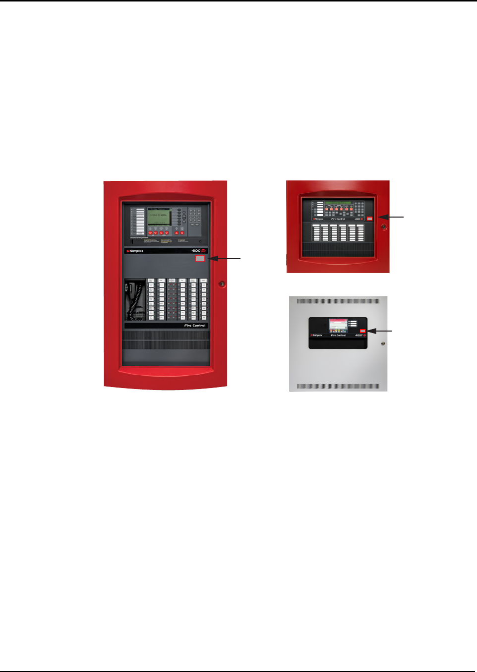
FCC/IC LABEL
The modular transmitter 3G9080 or LT0080 is labeled with its own FCC ID and IC number. When
the module is installed inside the host device and the FCC ID/IC of the module
is not visible, the host device displays the provided label referring to the FCC ID and IC of the
enclosed module. This label is shipped together with the module and it is the
responsibility of the integrator to apply it to the exterior of the enclosure, as displayed in the
following figure.
Le modulaire émetteur 3G9080 ou LT9080 est étiqueté avec son propre ID FCC et le numéro IC.
Lorsque le module est installé à l'intérieur du dispositif hôte et la FCC ID / IC du module ne soit
pas visible, le dispositif d'accueil affiche l'étiquette fournie se référant à l'ID FCC et IC du module
ci-joint. Ce label est livré avec le module et il est de la responsabilité de l'intégrateur de l'appliquer
à l'extérieur de l'enceinte, comme indiqué dans la figure suivante.
Model 3G9800
Contains FCC ID: F53173G9080
Contains IC: 160A-3G9080
Model LT9080
Contains FCC ID: F5317LT9080
Contains IC: 160A-LT9080
4100ES
Label
Placement
4010ES
Label
Placement
4007ES
Label
Placement
Cautions, warnings, and regulatory information, continued
5
Connected Services Gateway Cellular Module installation guide
Introduction The Connected Services Gateway Cellular Module is an optional module used with the Connected
Services Gateway Module (CSGM). The cellular module connects the CSGM to connected
services through a cellular network.
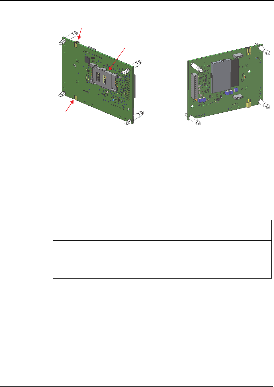
Figure 1.The Connected Services Gateway Cellular Module
You must install one or more antennae depending on the network of your chosen cellular module.
AT&T 3G cellular modules require one antenna. Verizon LTE cellular modules require two
antennae, referred to as primary and secondary antennae. Each kit includes the correct number of
harnesses you require for the cellular module you are installing. Refer to Table 1 for a list of PIDs.
In the case of poor signal strength at the FACU, an optional antenna extension kit may be
required. Refer to Table 2 for compatible extension kit information.
Table 1: Cellular Module PIDs
Cellular Module kit
description
Cellular Module kit PIDs for
CSGMs mounted in the FACU
Cellular Module kit
PIDs for CSGMs mounted in
an external box
Verizon, LTE 4100-6400
4010-6400
4007-6400
4100-6402
4010-6402
4007-6402
AT&T, 3G with 2G
fall back
4100-6401
4010-6401
4007-6401
4100-6403
4010-6403
4007-6403
Top side of the cellular module Bottom side of the cellular module
JK3
Sim card carrier
JK4
Overview
6
Connected Services Gateway Cellular Module installation guide
Introduction
The Connected Services Gateway Cellular Module attaches to the CSGM, which comes
pre-installed in new FACUs.
Specifications Refer to Table 3 for cellular module electrical requirements and for environmental limitations.
Note 1: When the SPES powers the CSGM, add the current draw of the cellular module to the current draw of
the CSGM, and calculate the 24 V battery draw using the SPES current draw table in the
Specifications section of Power over Ethernet Switch Module installation guide 579-1250.
Table 2: Antenna extension kit PIDs
Cellular Module Extension antenna kits Compatible extension antenna kit
PIDs
Verizon, LTE 15 feet (4.57 m) Antenna
extension kit
4100-6407
4010-6407
4007-6407
25 feet (7.62 m) Antenna
extension kit
4100-6408
4010-6408
4007-6408
50 feet (15.24 m) Antenna
extension kit
4100-6409
4010-6409
4007-6409
AT&T, 3G with 2G
fall back
15 feet (4.57 m) Antenna
extension kit
4100-6404
4010-6404
4007-6404
25 feet (7.62 m) Antenna
extension kit
4100-6405
4010-6405
4007-6405
50 feet (15.24 m) Antenna
extension kit
4100-6406
4010-6406
4007-6406
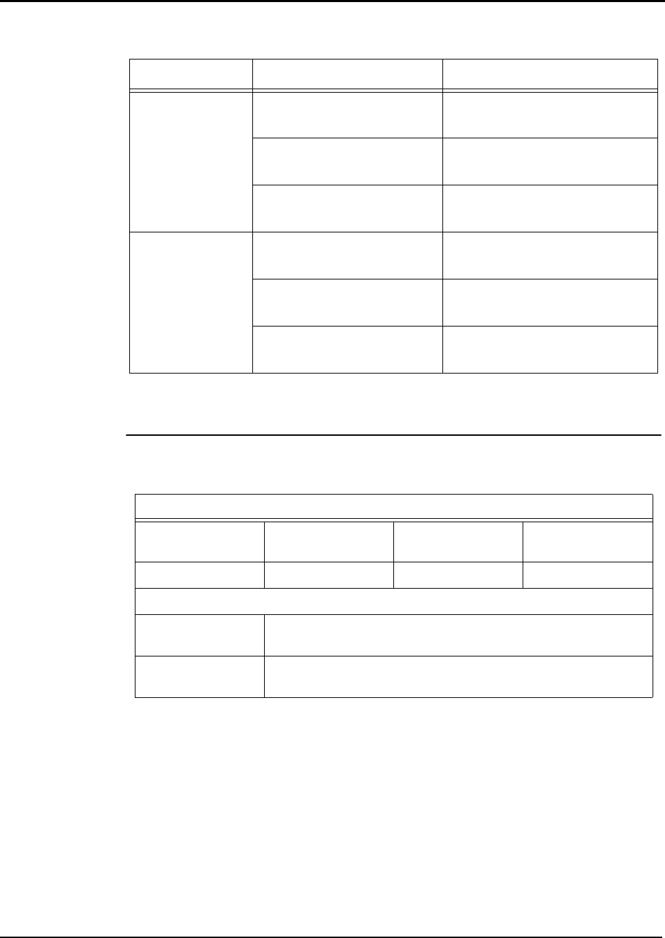
Table 3: Electrical and environmental specifications
Electrical specifications
Voltage DC Nominal 24V draw
through the CSGM
24V battery Powered from
SPES - see Note 1.
Current DC 40 mA 40 mA 30 mA
Environmental specifications
Temperature Normal operation with ambient temperature outside the cabinet at
32F to 120.2F (0C to 49C).
Humidity Normal operation under non-condensing humidity conditions up to
93% relative humidity at 100.4F (38C)
Overview, continued
7
Connected Services Gateway Cellular Module installation guide
Mounting the
cellular module
Note: The header connectors are located on the bottom of the cellular module. The SIM card carrier is located
on the top.
To mount the cellular module perform the following steps:
1. Insert the SIM card into the SIM card carrier.
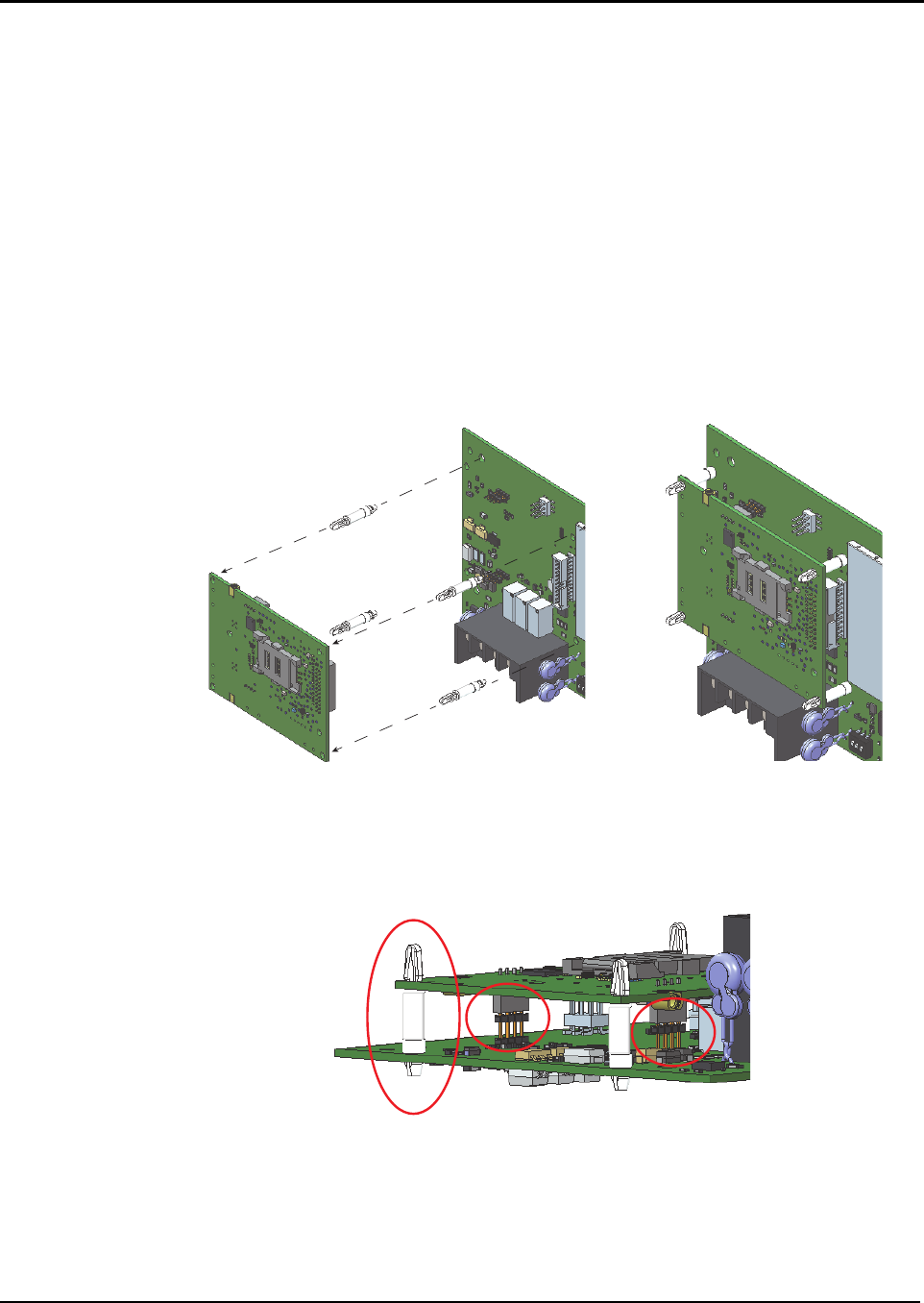
2. Push the four nylon standoffs through the bottom of the cellular module. The longer snap lock
ends click through the top of the cellular module, see Figure 2.
3. Align the connectors on the cellular module with the matching connectors on the CSGM.
Note: The main connector is shrouded and only inserts correctly. Standoffs ensure the connectors on both
modules align correctly.
4. Press the cellular module onto the CSGM until the standoffs snap into place.
5. Verify that the two smaller connectors insert correctly, see Figure 3. If you insert the connectors
incorrectly, do the following:
• Pinch the locking tops of the four adjacent standoffs to loosen the cellular module
from the CSGM.
• Realign the cellular module and repeat steps 3 to 5.
6. Place the FCC label included in the cellular module kit on the box that you installed the CSGM
in. Ensure that it is visible when the doors of the FACU are closed.
Figure 2. Connecting the cellular module to the CSGM
Figure 3. Connectors inserted correctly
Installing the cellular module
8
Connected Services Gateway Cellular Module installation guide
Overview You can mount the antennae for the cellular module in three locations as follows:
• Directly on the FACU that the CSGM is installed in.
• On the wall using an extension cable or bracket.
• Directly on the CSGM external box.
Notes:
• You can use a combination of the mounting locations listed above for installations requiring more than
one antenna.
• The cables and antennae included in the cellular module kit are identical. You can use either antenna as
the primary or secondary antenna mounting.
• The antennae are omni-directional. You do not need to align them to a particular compass direction.
Mounting the
antenna directly
on the FACU
Consult the following guidelines before mounting the antenna directly on the 4100ES, 4010ES, or
4007ES FACUs:
• The antenna cables are 36 inches long. They reach all areas on top of the 4100ES and
4010ES FACUs with the CSGM mounted in the top bay.
• The antenna cables reach all areas of the 4007ES FACU.
• When you are flush-mounting a 4007ES, leave at least two inches of wall protrusion to mount
the antenna.
• Run the antenna cables as power-limited wiring.
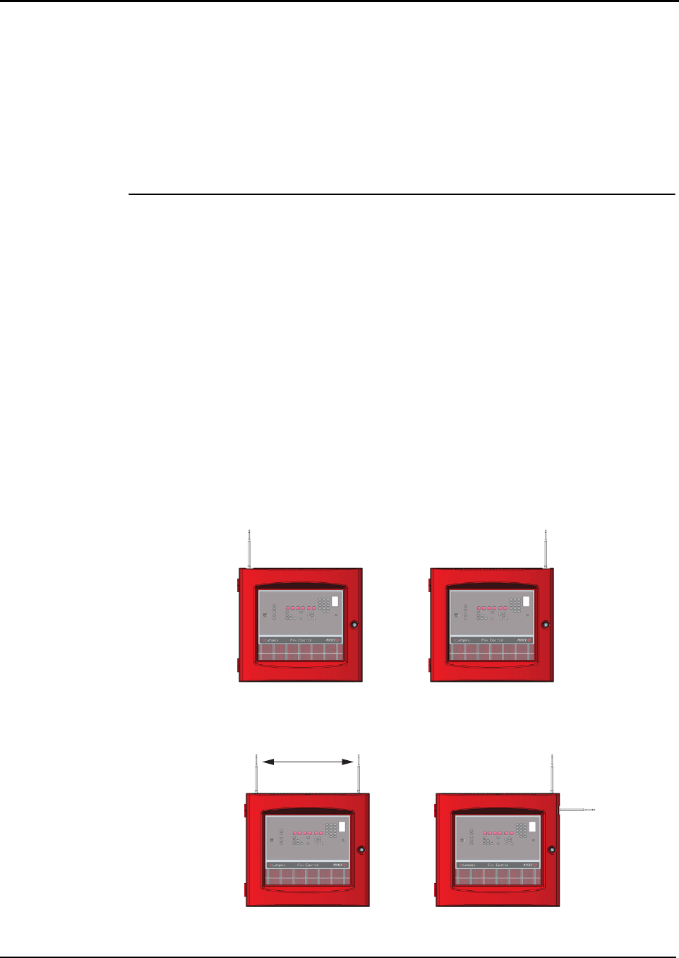
• Always vertically align the primary antenna. You can mount this antenna close to either the
top left or right edge of the FACU to conserve space on the unit for conduit entry. See Figure
4.
• Mount the secondary antenna vertically at least 5.5 inches (14 cm) away from the primary
antenna and other antennae. Alternatively, you can mount the secondary antenna at a 90
degree angle from the primary antenna at the side of the FACU, without spacing restrictions.
See Figure 5.
• If you choose to mount the secondary antenna on the side of the FACU, place it opposite the
hinge side of the door, and at least TBD away from adjunct FACUs.
• Position antennae at least 5.5 inches (14 cm) away from cables, conduit, and metal
structures.
Figure 4. Primary antenna mounting examples
Figure 5. Primary and secondary antennae mounting example
Option 1 Option 2
Option 1 Option 2
5.5 inches (14 cm )
minimum
Antenna mounting guidelines

9
Connected Services Gateway Cellular Module installation guide
Mounting the
antenna on the
wall using an
antenna extension
You can use antenna extensions to mount the antenna remotely in an area with better cellular
signal and greater mounting space. For antenna extensions, use the same internal cables as
when you mount antennae directly on the FACU. Rules for mounting antenna extensions are less
restrictive than for mounting on the FACU.
Antennae are pre-installed with the extension and wall brackets in antenna extension kits. Consult
the following guidelines before installing the antenna extension:
• You can place holes to mount antenna extension cables anywhere on the box. Ensure that
the 36 inch cable can reach the mounting hole from the cellular module location, which is
usually in the top bay.
• You must leave a minimum of 3/4 inches (19 mm) around the center of the antenna cable
connector for ease of installation.
• Always mount remote antennae vertically.
• Antenna extension cables are power-limited.
• If you mount more than one antenna, mount the extended antennae at least two inches apart.
Further than two inches (5 cm) apart is better.
• You cannot link antenna extensions together. Use only one extension for each antenna.
• Use the full length of the antenna extension cable. Do not cut or splice the cable.
• Coil excess cable near the FACU. Do not coil the 15 foot extension cable tighter than a six
inch (15.3 cm) diameter loop. Do not coil the 15 foot and 25 foot cables tighter than a 12 inch
(30.5 cm) diameter loop.
Mounting the
antenna on the
CSGM External
Box
Consult the following guidelines before mounting the antenna on the CSGM External Box:
• Antenna holes are pre-located with knockouts in the CSGM External Box. Choose any two of
these holes to mount the antennae.
• Mount the primary antenna vertically aligned.
• The cellular module kit for the external box comes with a shorter antenna cable that reaches
all of the knockouts in the external box.
Mounting the antenna
579-1248
Rev. 6
R
Mounting the
antenna
Before you begin, refer to Installing the cellular module for information about the installation type
you are performing. All of the parts you require to mount the antenna cable are included in the
cellular module kit.
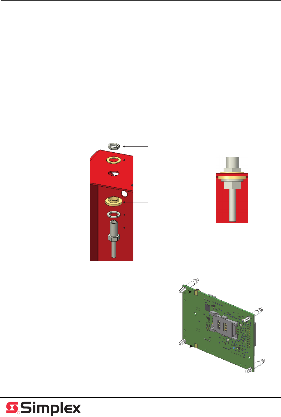
To mount the antenna, perform the following steps:
1. Drill or punch a 21/64 inch (8.3344 mm) hole in the unit. If you are mounting the antenna on the
external box, use knockouts instead.
2. Remove the nut from the SMA connector, leaving the lock washer in place.
3. Place the lower, thicker nylon shoulder washer on top of the lock washer, with the collar side
facing up, see Figure 6.
4. Insert the SMA connector through the hole from the inside of the unit.
5. Place the second, thinner nylon washer over the SMA connector.
6. Replace the nut and tighten firmly, so that the cable does not spin freely.
7. Connect either the antenna or the extension cable to the SMA connector.
8. Route the antenna cable through the unit as power-limited wiring to the cellular module on the
CSGM.
Note: The primary antenna connects to the cellular module at J4. The secondary antenna connects to the
cellular module at J3.
9. Press the antenna cable MMCX connector firmly to the connection on the cellular module until it
snaps into place.
Figure 6. Installing the antenna cable
Figure 7. Antenna connectors on the cellular module
Nut
Nylon washer
Nylon shoulder washer
Lock washer
SMA connector
JK4 - primary antenna connection
JK3 - secondary antenna connection
Mounting the antenna, continued