Tyco Safety Canada 18PG9862 Wireless ceiling PIR presence/security detector User Manual My
Digital Security Controls Ltd. Wireless ceiling PIR presence/security detector My
Users Manual
PGx862 Wireless ceiling PIR presence/security detector Installation Instructions ©2018 Tyco Security Products, Toronto, Canada www.dsc.com Tech. Support: 1-800-387-3630 1
D-307205
PG9862/PG8862/PG4862 Overview
The PGx862 is a smart wireless ceiling PIR presence/security detector
(selected mode) that creates a 360° coverage area to detect the move-
ment of intruders in indoor areas.
The detector has the following features.
lPresence detection mode - active 15 minutes after installation
(power-up).
lBuilt-in link quality indicators eliminate the need for the installer to
physically approach the control panel and reduce installation time.
lThe device supports temperature and light level reports to com-
patible alarm systems that support temperature and light sensors.
lTamper protection.
lPowerG two-way Frequency Hopping Spread Spectrum FHSS-
TDMA technology.
lThe Advanced True Motion Recognition™ algorithm (patented)dis-
tinguishes between the true motion of an intruder and any other dis-
turbances which may cause false alarms.
NOTE: For UL installations, the detector is for use with UL listed con-
trol units only.
Legend
D
A
B
C
E
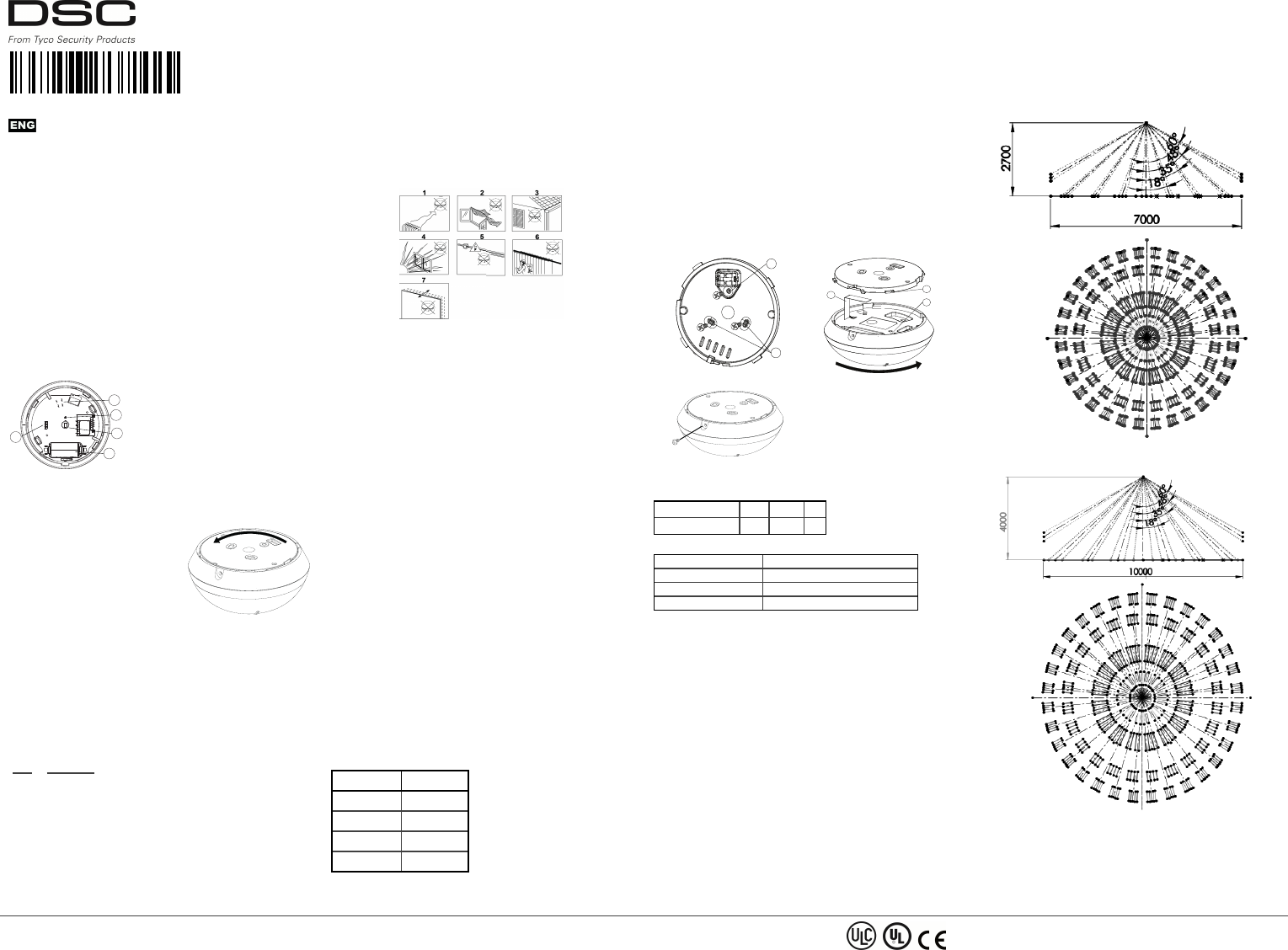
Figure 1. Internal view
ATamper protection
BLight sensor
CPyro sensor
DBattery
ELEDs
Inserting or replacing the battery
If the battery is already installed, pull the activation strip that protrudes
from the back of the detector.
1. To separate the detector from the
mounting bracket, rotate the bracket
anticlockwise and pull it from the
detector.
2. Insert the battery while observing
polarity.
3. Align the bracket tabs with the
detector slots and rotate the detector
clockwise to verify that it is securely
attached.
Figure 2. Removing the
bracket
NOTE: It is recommended to wait about 1 minute after battery
removal before inserting the new battery.
Caution! Risk of explosion if battery is replaced by an incorrect type.
Dispose of used batteries according to the manufacturer's instructions
and according to local rules and regulations.
Enrollment
Refer to the panel installation manual for the enrollment procedure.
A general description of the procedure is provided in the following
flow chart:
Step Procedure
1 See the installation manual for the alarm system that the
device is being enrolled on to ensure that the proper steps
are used.
2 Enter the Device Enrollment option through the specified
method and select the appropriate option to add the new
device.
3 Enrollthe device by either inserting the battery to power on
the device until the enrollment is detected, or by entering the
Device ID.
4 Select the desired Zone Number.
5 Configure any device parameters that are required.
6 Mount and test the detector. See Walk testing for information
on testing the device. In addition, see the alarm systems
installation manual that the device is enrolled on for other
test procedures that are required.
NOTE: If the detector is already enrolled, you can configure the
detector parameters by programming the system, see the alarm sys-
tems installation manual for more information about device para-
meters.
NOTE: When enrolling the PGx862 detector to wireless panels
(WP80XX) with version 19.4 or lower, the detector will be enrolled as
motion detector, ID 120-xxxx, and labelled ‘Motion Sens’ in the panel.
Installation tips
Use the following as a guide for locating a suitable mounting location.
Figure 3. General Guidelines
1. Keep away from heat sources.
2. Do not expose to air drafts.
3. Do not install outdoors.
4. Avoid direct sunshine.
5. Do not install near high voltage electrical lines.
6. Do not install behind partitions.
7. Mount on a solid stable surface.
WARNING! Do not partially or completely obscure the detector’s
field of view.
WARNING! To comply with FCC and ISED Canada RF exposure com-
pliance requirements, the PIR detector should be located at a distance
of at least 20 cm from all persons during normal operation. The anten-
nas used for this product must not be co- loc ated or operated in con-
junction with any other antenna or transmitter.
NOTE: The PGx862 Wireless ceiling PIR presence/security detector
shall be installed and used within an environment that provides the pol-
lution degree max 2 and overvoltages category II in NON
HAZARDOUS LOCATIONS. The equipment is designed to be
installed only by qualified service persons.
NOTE: PGx862 shall be installed in accordance with the Standard for
Installation and Classification of Burglar and Holdup Alarm Systems,
UL 681.
Walk testing
Before permanently mounting any wireless device, temporarily mount
the device and perform a walk test. Perform a walk test of the cov-
erage area at least once a year to ensure that the detector is working
correctly.
After inserting the battery or closing the device, the detector will auto-
matically enter a stability period where the LED flashes RED for 90
seconds. Walk test the coverage area, the LED lights red each time
your motion is detected followed by 3 LED blinks. The color of the 3
LED blinks indicate the received signal strength. In walk-test mode,
regardless of the LED Selection status, the LED lights upon every
motion detection. After 15 minutes the detector automatically enters
normal mode.
The following table indicates the received signal strength.
LED Response Signal Strength
Green LED blinks STRONG
Orange LED blinks GOOD
Red LED blinks POOR
No blinks No communication
IMPORTANT! Only GOOD or STRONG signal strengths are accept-
able. If you receive a POOR signal from the device, re-locate it and
re-test until a GOOD or STRONG signal is received.
NOTE: For UL/ULC installations, only STRONG signal leve ls a re
acceptable. After installation verify the product functionality in con-
junction with the compatible control panels HSM2HOST9, HS2LCDRF
(P)9, HS2ICNRF(P)9, PG9920, WS900-19, and WS900-29.
NOTE: For detailed Placement instructions refer to the control panel
reference manual.
Walk-test the coverage area by walking across the far end of the cov-
erage pattern in both directions. The red LED lights each time your
motion is detected followed by a steady LED signal strength indication.
Mounting the device
1. Mark and drill two holes in the mounting surface. If you install
tamper protection on the detector, mark and drill one hole for the
tamper protection and one hole for one of the other available
slots.
2. Fasten the bracket to the mounting surface with the two screws.
3. Align the bracke t tabs with the detector slots and rotate the
detector clockwise. Verify that it is securely attached.
4. Fasten the detector to the bracket with the screw.
A
B
Figure 4. Fastening the bracket
D
E
C
Figure 5. Attaching the detector
Figure 6. Fastening the detector
ATamper protection
BBracket screw slots
CIsolation strip
DBracket tabs
EDetector slots
The following table outlines the detection distance in relation to the
mounting height.
Height 2 m 3 m 4 m
Detection distance 3.1 m 3.75 m 5 m
LED Operation
LED Indications Event
Red LED blinks Stabilization (warm-up 90 seconds)
Red LED on 0.2 seconds Tamper open/close
Red LED on 2 seconds Intruder alarm
Temperature and light display
For instructions on displaying the temperature of zones on the correct
panel as measured by the PGx862, refer to the panel installation guide.
Specifications
GENERAL
Detector Type
One pyroelectric sensor operating in a dual separated configuration
OPTICAL
Lens Data
Fresnel type lens.
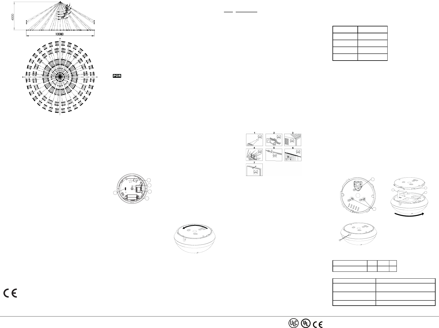
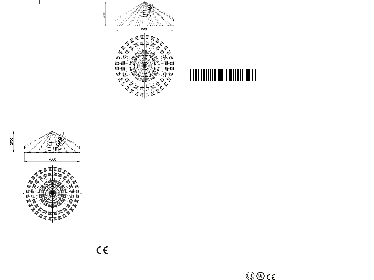
Number of beams: 72
Max. coverage
Ø10 m/360° at the maximum installation height of 4 m
ELECTRICAL
Power Supply: Type C
InternalBattery
3V Lithium battery, type CR-123A. For UL installations, use
Panasonic and GP only
Nominal Battery Capacity: 1450 mAh
Battery Life (typical use)
Minimum 1 year. For typical use (security mode), 5 years (not veri-
fied by UL).
Low Battery Threshold: 2.4 V
NOTE: Inability to connect with wireless network, or wireless link
quality no higher than 20% may significantly reduce the expected bat-
tery life.
Battery Power Test
Performed immediately upon battery insertion and periodically after
every several hours.
The power supply is type C in accordance with EN 50131-6 Docu-
mentation – Clause 6.
Current Consumption
20 μA average quiescent , maximum 150 mA (during transmission)
Figure 7. Beam distribution at 2.7 m
Figure 8. Beam distribution at 4 m
FUNCTIONAL
Alarm Period: 2 seconds
WIRELESS
Frequency
Europe and rest of world: 433-434 MHz, 868- 869 MHz USA: 912-919
PGx862 Wireless ceiling PIR presence/security detector Installation Instructions ©2018 Tyco Security Products, Toronto, Canada www.dsc.com Tech. Support: 1-800-387-3630 2
MHz
NOTE: Only devices in frequency band 915 MHz are UL/ULC listed.
Communication
Protocol: PowerG
Supervision: Signaling at 256 s intervals
Tamper Alert
Reported when a tamper event occurs and in any subsequent mes-
sage, until the tamper switch is restored.
MOUNTING
Height: 2 m to 4 m
Installation Options: Ceiling surface
ENVIRONMENTAL
RF Immunity
20 V/m up to 1000 MHz, 10 V/m up to 2700 MHz
Operating Temperatures
-10 °C to 55 °C (14 °F to 131 °F).
NOTE: UL verified operation range 0°C to 49°C only.
Storage Temperatures
-20 °C to 60 °C (-4 °F to 140 °F).
Humidity
Average relative humidity of up to approximately 75% non-con-
densing. For 30 days per year the relative humidity may vary between
85% and 95% non-condensing.
For UL installations: 5% to 93% with no condensation
PHYSICAL
Size (diameter): 10.6 cm
Weight (with battery): 110 g (3.88 oz)
Color: White
COMPATIBLE RECEIVERS
This device can be used with DSC panels and receivers that use
PowerG technology.
NOTE: Only devices operating in band 912-919MHz are UL/ULC lis-
ted.
UL/ULC Notes
Only model PG9862 operating in the frequency band 912-919MHz is
UL/ULC listed. The PG9862 has been listed by UL for commercial and res-
idential burglary applications and by ULC for residential burglary applic-
ations in accordance with the requirements in the Standards UL 639 and
ULC-S306 for Intrusion Detection Units.
For UL/ULC installations use these device only in conjunction with com-
patible DSC wireless receivers: HSM2HOST9, HS2LCDRF(P)9, HS2ICNRF(P)
9, PG9920, WS900-19, and WS900-29. After installation verify the product
functionality in conjunction with the compatible receiver used.
FCC COMPLIANCE STATEM ENT
WARNING!Changes or modifications to this unit not expressly approved by
the party responsible for compliance could void the user’s authority to oper-
ate the equipment.
This device has been tested and found to comply with the limits for a Class
B digital device, pursuant to Part 15 of the FCC Rules. These limits are
designed to provide reasonable protection against harmful interference in res-
idential installations. This equipment generates uses and can radiate radio fre-
quency energy and, if not installed and used in accordance with the
instructions, may cause harmful interference to radio and television reception.
However, there is no guarantee that interference will not occur in a particular
installation. If this device does cause such interference, which can be verified
by turning the device off and on, the user is encouraged to eliminate the inter-
ference by one or more of the following measures:
– Re-orient or re-locate the receiving antenna.
– Increase the distance between the device and the receiver.
– Connect the device to an outlet on a circuit different from the one that sup-
plies power to the receiver.
– Consult the dealer or an experienced radio/TV technician.
FCC ID: F5318PG9862
Innovation Science and Economic Development Canada (ISED)
Statement
This equipment complies with FCC and ISED Canada RF radiation exposure
limits set forth for an uncontrolled environment.
This device complies with FCC Rules Part 15 and with ISED Canada licence-
exempt RSS standard(s). Operation is subject to the following two con-
ditions: (1) This device may not cause harmful interference, and (2) this
device must accept any interference that may be received or that may cause
undesired operation.
Le present appareil est conforme aux CNR d'ISED Canada applicables aux
appareils radio exempts de licence. L'exploitation est autorisee aux deux con-
ditions suivantes :(1) l'appareil ne doit pas produire de brouillage, et (2) l'util-
isateur de l'appareil doit accepter tout brouillage radioelectrique subi, meme si
le brouillage est susceptible d'en compromettre le fonctionnement.
IC: 160A-PG9862
Europe: CE/EN (EN50131-2-2 GRADE 2, CLASS II, EN50131-6
Type C) listed PG8862: 868 MHz PG4862: 433 MHz.
According to EN 50131-1, this equipment can be applied in installed sys-
tems up to and including Security Grade 2, Environmental Class II. UK: The
PG8862 is suitable for use in systems installed to conform to PD6662 at
Grade 2 and environmental class 2 BS8243. The Power G peripheral devices
have two-way communication functionality, providing additional benefits as
described in the technical brochure. This functionality has not been tested to
comply with the respective technical requirements and should therefore be
considered outside the scope of the product’s certification.
Simplified EU declaration of conformity
Hereby, Tyco Safety Products Canada Ltd. declares that the radio equipment
type is in compliance with Directive 2014/53/EU.
The full text of the EU declaration of conformity is available at the following
internet address:
PG4862: http://dsc.com/pdf/1710001
PG8862: http://dsc.com/pdf/1710002
Frequency band Maximum power
433.04 MHz - 434.79 MHz 10 mW
868.0 MHz - 868.6 MHz 10 mW
868.7 MHz - 869.2 MHz 10 mW
European single point of contact: Tyco Safety Products, Voltaweg 20, 6101
XK Echt, Netherlands.
Limited Warranty
Digital Security Controls (DSC) warrants that for a period of twelve months
from the date of purchase, the product shall be free of defects in materials and
workmanship undernormal use and that in fulfilment of any breach of such
warranty, DSC shall, at its option, repair or replace the defective equipment
upon return of the equipment to its factory. This warranty applies only to
defects in parts and workmanship and not to damage incurred in shipping or
handling, or damage due to causes beyond the control of DSC such as light-
ning, excessive voltage, mechanical shock, water damage, or damage arising
out of abuse, alteration or improper application of the equipment.
The foregoing warranty shall apply only to the original buyer, and is and
shall be in lieu of any and all otherwarranties, whetherexpressed or implied
and of all other obligations or liabilities on the part of DSC. This warranty
contains the entire warranty. Digital Security Controls neither assumes
responsibility for, nor authorizes any other person purporting to act on its
behalf to modify or to change this warranty, nor to assume for it any other
warranty or liability concerning this product. In no event shall DSC be liable
for any direct or indirect or consequential damages, loss of anticipated profits,
loss of time or any other losses incurred by the buyerin connection with the
purchase, installation or operation or failure of this product.
Warning: Digital Security Controls recommends that the entire system be
completely tested on a regular basis. However, despite frequent testing, and
due to, but not limited to, criminal tampering or electrical disruption, it is
possible for this product to fail to perform as expected.
IMPORTANT - READ CAREFULLY: DSC Software purchased with or
without Products and Components is copyrighted and is purchased under the
following license terms:
This End-User License Agreement (“EULA”) is a legal agreement between You
(the company, individual or entity who acquired the Software and any related
Hardware) and Digital Security Controls, a division of Tyco Safety Products
Canada Ltd. (“DSC”), the manufacturer of the integrated security systems and
the developer of the software and any related products or components
(“HARDWARE”) which You acquired. If the DSC software product
(“SOFTWARE PRODUCT” or “SOFTWARE”) is intended to be accompanied
by HARDWARE, and is NOT accompanied by new HARDWARE, You may
not use, copy or install the SOFTWARE PRODUCT. The SOFTWARE
PRODUCT includes computer software, and may include associated media,
printed materials, and “online” or electronic documentation. Any software
provided along with the SOFTWARE PRODUCT that is associated with a sep-
arate end-user license agreement is licensed to You under the terms of that
license agreement.
By installing, copying, downloading, storing, accessing or otherwise using
the SOFTWARE PRODUCT, You agree unconditionally to be bound by the
terms of this EULA, even if this EULA is deemed to be a modification of any
previous arrangement or contract. If You do not agree to the terms of this
EULA, DSC is unwilling to license the SOFTWARE PRODUCT to You, and
You have no right to use it.
SOFTWARE PRODUCT LICENSE
The SOFTWARE PRODUCT is protected by copyright laws and international
copyright treaties, as well as other intellectual property laws and treaties. The
SOFTWARE PRODUCT is licensed, not sold.
1. GRANT OF LICENSE This EULA grants You the following rights:
(a) Software Installation and Use - For each license You acquire, You may
have only one copy of the SOFTWARE PRODUCT installed.
(b) Storage/Network Use - The SOFTWAREPRODUCT may not be installed,
accessed, displayed, run, shared or used concurrently on or from different
computers, including a workstation, terminal or other digital electronic device
(“Device”). In other words, if You have several workstations, You will have
to acquire a license for each workstation where the SOFTWARE will be used.
(c) Backup Copy - You may make back-up copies of the SOFTWARE
PRODUCT, but You may only have one copy per license installed at any
given time. You may use the back-up copy solely for archival purposes.
Except as expressly provided in this EULA, You may not otherwise make
copies of the SOFTWARE PRODUCT, including the printed materials accom-
panying the SOFTWARE.
2. DESCRIPTION OF OTHER RIGHTS AND LIMITATIONS
(a) Limitations on Reverse Engineering, Decompilation and Disassembly -
You may not reverse engineer, decompile, or disassemble the SOFTWARE
PRODUCT, except and only to the extent that such activity is expressly per-
mitted by applicable law notwithstanding this limitation. You may not make
any changes or modifications to the Software, without the written permission
of an officer of DSC. You may not remove any proprietary notices, marks or
labels from the Software Product. You shall institute reasonable measures to
ensure compliance with the terms and conditions of this EULA.
(b) Separation of Components - The SOFTWARE PRODUCT is licensed as a
single product. Its component parts may not be separated for use on more
than one HARDWARE unit.
(c) Single INTEGRATED PRODUCT - If You acquired this SOFTWARE with
HARDWARE, then the SOFTWARE PRODUCT is licensed with the
HARDWAREas a single integrated product. In this case, the SOFTWARE
PRODUCT may only be used with the HARDWARE as set forth in this
EULA.
(d) Rental - You may not rent, lease or lend the SOFTWAREPRODUCT. You
may not make it available to others or post it on a server or web site.
(e) Software Product Transfer - You may transferall of Your rights under this
EULA only as part of a permanent sale or transfer of the HARDWARE,
provided You retain no copies, You transfer all of the SOFTWARE
PRODUCT (including all component parts, the media and printed materials,
any upgrades and this EULA), and provided the recipient agrees to the terms
of this EULA. If the SOFTWARE PRODUCTis an upgrade, any transfer must
also include all prior versions of the SOFTWARE PRODUCT.
(f) Termination - Without prejudice to any other rights, DSC may terminate
this EULA if You fail to comply with the terms and conditions of this EULA.
In such event, You must destroy all copies of the SOFTWARE PRODUCT
and all of its component parts.
(g) Trademarks - This EULA does not grant You any rights in connection
with any trademarks or service marks of DSC or its suppliers.
3. COPYRIGHT - All title and intellectual property rights in and to the
SOFTWARE PRODUCT (including but not limited to any images, pho-
tographs, and text incorporated into the SOFTWARE PRODUCT), the accom-
panying printed materials, and any copies of the SOFTWARE PRODUCT, are
owned by DSC or its suppliers. You may not copy the printed materials
accompanying the SOFTWARE PRODUCT. All title and intellectual property
rights in and to the content which may be accessed through use of the
SOFTWARE PRODUCT are the property of the respective content owner and
may be protected by applicable copyright or other intellectual property laws
and treaties. This EULA grants You no rights to use such content. All rights
not expressly granted under this EULA are reserved by DSC and its suppliers.
4. EXPORT RESTRICTIONS - You agree that You will not export or re-export
the SOFTWARE PRODUCT to any country, person, or entity subject to Cana-
dian export restrictions.
5. CHOICE OF LAW - This Software License Agreement is governed by the
laws of the Province of Ontario, Canada.
6. ARBITRATION - All disputes arising in connection with this Agreement
shall be determined by final and binding arbitration in accordance with the
Arbitration Act, and the parties agree to be bound by the arbitrator’s decision.
Th e place o f arbitration shall be Toron to, Canada, and the langu age of th e
arbitration shall be English.
7. LIMITED WARRANTY
(a) NO WARRANTY - DSC PROVIDES THE SOFTWARE “AS IS” WITHOUT
WARRANTY. DSC DOES NOT WARRANT THAT THE SOFTWARE WILL
MEET YOUR REQUIREMENTS OR THAT OPERATION OF THE
SOFTWARE WILL BE UNINTERRUPTED OR ERROR-FREE.
(b) CHANGES IN OPERATING ENVIRONMENT - DSC shall not be respons-
ible for problems caused by changes in the operating characteristics of the
HARDWARE, or for problems in the interaction of the SOFTWARE
PRODUCT with non-DSC-SOFTWARE or HARDWARE PRODUCTS.
(c) LIMITATION OF LIABILITY; WARRANTY REFLECTS ALLOCATION OF
RISK - IN ANY EVENT, IF ANY STATUTE IMPLIES WARRANTIES OR
CONDITIONS NOT STATED IN THIS LICENSEAGREEMENT, DSC’S
ENTIRE LIABILITY UNDER ANY PROVISION OF THIS LICENSE
AGREEMENT SHALL BE LIMITED TO THE GREATER OF THE AMOUNT
ACTUALLY PAID BY YOU TO LICENSE THE SOFTWARE PRODUCT AND
FIVE CANADIAN DOLLARS (CAD$5.00). BECAUSE SOME
JURISDICTIONS DO NOT ALLOW THE EXCLUSION OR LIMITATION OF
LIABILITY FOR CONSEQUENTIAL OR INCIDENTAL DAMAGES, THE
ABOVE LIM ITATION MAY NOT APPLY TO YOU.
(d) DISCLAIMER OF WARRANTIES - THIS WARRANTY CONTAINS THE
ENTIRE WARRANTY AND SHALL BE IN LIEU OF ANY AND ALL OTHER
WARRANTIES, WHETHER EXPRESSED OR IMPLIED (INCLUDING ALL
IM PLIED WARRANTIES OF MERCHANTABILITY OR FITNESS FOR A
PARTICULAR PURPOSE) AND OF ALL OTHER OBLIGATIONS OR
LIABILITIES ON THE PART OF DSC. DSC MAKES NO OTHER
WARRANTIES. DSC NEITHER ASSUMES NOR AUTHORIZES ANY
OTHER PERSON PURPORTING TO ACT ON ITS BEHALF TO MODIFY OR
TO CHANGE THIS WARRANTY, NOR TO ASSUME FOR IT ANY OTHER
WARRANTY OR LIABILITY CONCERNING THIS SOFTWARE PRODUCT.
(e) EXCLUSIVE REMEDY AND LIMITATION OF WARRANTY - UNDER
NO CIRCUMSTANCES SHALL DSC BE LIABLE FOR ANY SPECIAL,
INCIDENTAL, CONSEQUENTIAL OR INDIRECT DAMAGES BASED UPON
BREACH OF WARRANTY, BREACH OF CONTRACT, NEGLIGENCE,
STRICT LIABILITY, OR ANY OTHER LEGAL THEORY. SUCH DAMAGES
INCLUDE, BUT ARE NOT LIMITED TO, LOSS OF PROFITS, LOSS OF THE
SOFTWARE PRODUCT OR ANY ASSOCIATED EQUIPMENT, COST OF
CAPITAL, COST OF SUBSTITUTE OR REPLACEMENT EQUIPMENT,
FACILITIES OR SERVICES, DOWN TIME, PURCHASERS TIME, THE
CLAIMS OF THIRD PARTIES, INCLUDING CUSTOMERS, AND INJURY
TO PROPERTY. WARNING: DSC recommends that the entire system be com-
pletely tested on a regular basis. However, despite frequent testing, and due
to, but not limited to, criminal tampering or electrical disruption, it is pos-
sible for this SOFTWARE PRODUCT to fail to perform as expected.
The term IC before the radio certification number signifies that the Industry
Canada technical specifications were met. This Class B digital apparatus com-
plies with Canadian ICES-003. This device complies with RSS-247 of
Industry Canada. Operation is subject to the following two conditions: (1)
this device may not cause interference, and (2) this device must accept any
interference, including interference that may cause undesired operation of the
device. Cet appareil numérique de la classe B est conforme à la norme NMB-
003 du Canada. Ce dispositif satisfait aux exigences d’Industrie Canada, pre-
scrites dans le document CNR-247. son utilisation est autorisée seulement
aux conditions suivantes: (1) il ne doit pas produire de brouillage et (2) l’util-
isateur du dispositif doit être prêt à accepter tout brouillage radioélectrique
reçu, même si ce brouillage est susceptible de compromettre le fonc-
tionnement du dispositif.
Présentation de PG9862/PG8862/PG4862
Le PGx862 est un détecteur PIR sans fil de présence/sécurité intel-
ligent pour plafond (mode sélectionné) qui crée une zone de couver-
ture de 360° pour détecter le mouvement des intrus en intérieur.
Le détecteur présente les caractéristiques suivantes.
lMode Détection de présence – Actif 15 minutes après l'installation
(mise sous tension).
lLes indicateurs intégrés de qualité de la liaison évitent à l'in-
stallateur de devoir se trouver à proximité physique de la centrale
et réduisent le temps d'installation.
lL'appareil assure une fonction de signalement du niveau de tem-
pérature et de lumière aux systèmes d'alarme compatibles prenant
en charge les capteurs de température et de lumière.
lAuto-protection.
lTechnologie bidirectionnelle Power-G Frequency Hopping Spread
Spectrum FHSS-TDMA.
lL'algorithme avancé True Motion Recognition™ (breveté) fait la
distinction entre les mouvements réels d'un intrus et toute autre per-
turbation susceptible de déclencher de fausses alertes.
REMARQUE: Pour les installations certifiées, le détecteur ne doit
être utilisé qu'avec des unités de contrôle certifiées UL.
Légende
D
A
B
C
E
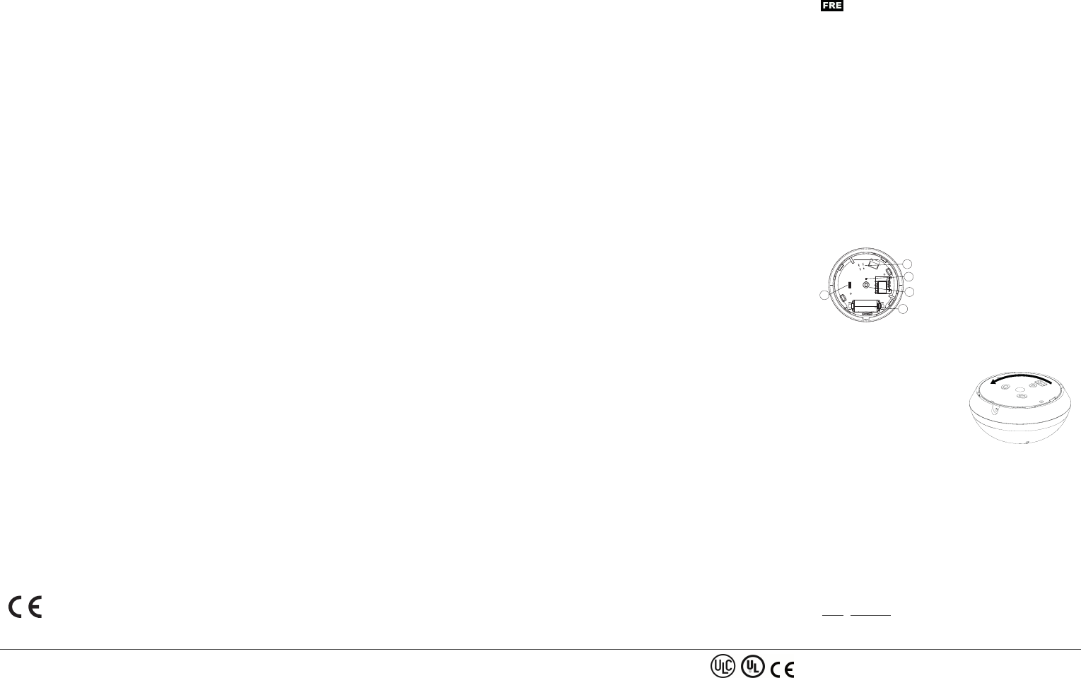
Figure 1. Vue interne
AAuto-protection
BDétecteur de lumière
CCapteur pyroélectrique
DPile
EVoyants
Insertion ou remplacement de la pile
Si la pile est déjà en place, tirez sur la languette d'activation dépassant
à l'arrière du détecteur.
1. Pour détacher le détecteur du sup-
port de montage, faites tourner le
support dans le sens contraire des
aiguilles d'une montre et extrayez-le
du détecteur.
2. Insérez de la pile en orientant con-
venablement les pôles.
3. Alignez les pattes du support sur les
encoches du détecteur et faites
tourner le détecteur dans le sens des
aiguilles d'une montre pour vous
assurer qu'il est solidement fixé.
Figure 2. Retrait du support
REMARQUE: Il est conseillé d'atte ndre 1 minute après le retrait de
la pile avant d'en insérer une neuve.
Avertissement! risque d'explosion si vous remplacez la pile par une
pile de type incorrect. Mettez les piles usagées au rebut en suivant les
instructions du fabricant et conformément aux règles et régle-
mentations locales.
Enregistrement
Pour des informations détaillées sur la procédure d'enregistrement,
consultez le manuel d'installation de la centrale.
Une description générale de la procédure est indiquée dans le tableau
suivant:
Étape Procédure
PGx862 Wireless ceiling PIR presence/security detector Installation Instructions ©2018 Tyco Security Products, Toronto, Canada www.dsc.com Tech. Support: 1-800-387-3630 3
1 Consultez le manuel d'installation du système d'alarme dans
lequel l'appareil est enregistré afin de suivre la procédure
adéquate.
2 Utilisez la méthode préconisée pour accéder à l'option d'en-
registrement de l'appareil et sélectionnez l'option cor-
respondante pour ajouter un nouvel appareil.
3 Enregistrez l'appareil, soit en insérant la pile pour mettre l'ap-
pareil sous tension jusqu'à ce que l'enregistrement soit
détecté, soit en saisissant l'ID de l'appareil.
4 Sélectionnez le Numéro de zone voulu.
5 Configurez les paramètres nécessaires de l'appareil.
6 Montez et testez le détecteur. Pour savoir comment tester
l'appareil, consultez la section Test de déplacement. Con-
sultez également le manuel d'installation des systèmes
d'alarme dans lesquels l'appareil est enregistré pour con-
naître la procédure à suivre.
REMARQUE: Si le détecteur est déjà enregistré, vous pouvez con-
figurer ses paramètres en programmant le système. Pour plus d'in-
formations sur les paramètres de l'appareil, consultez le manuel
d'installa tion des systèmes d'alarme.
REMARQUE: lors de l’enregistrement du détecteur PGx862 dans les
centrales sans fil (WP80XX) dotées de la version 19.4 ou inférieure,
celui-ci est enregistré en tant que détecteur de mouvements (ID 120-
xxxx) et identifié par ‘PERIF IR’ dans la centrale.
Conseils d'installation
Utilisez les informations suivantes pour identifier un emplacement de
montage adapté.
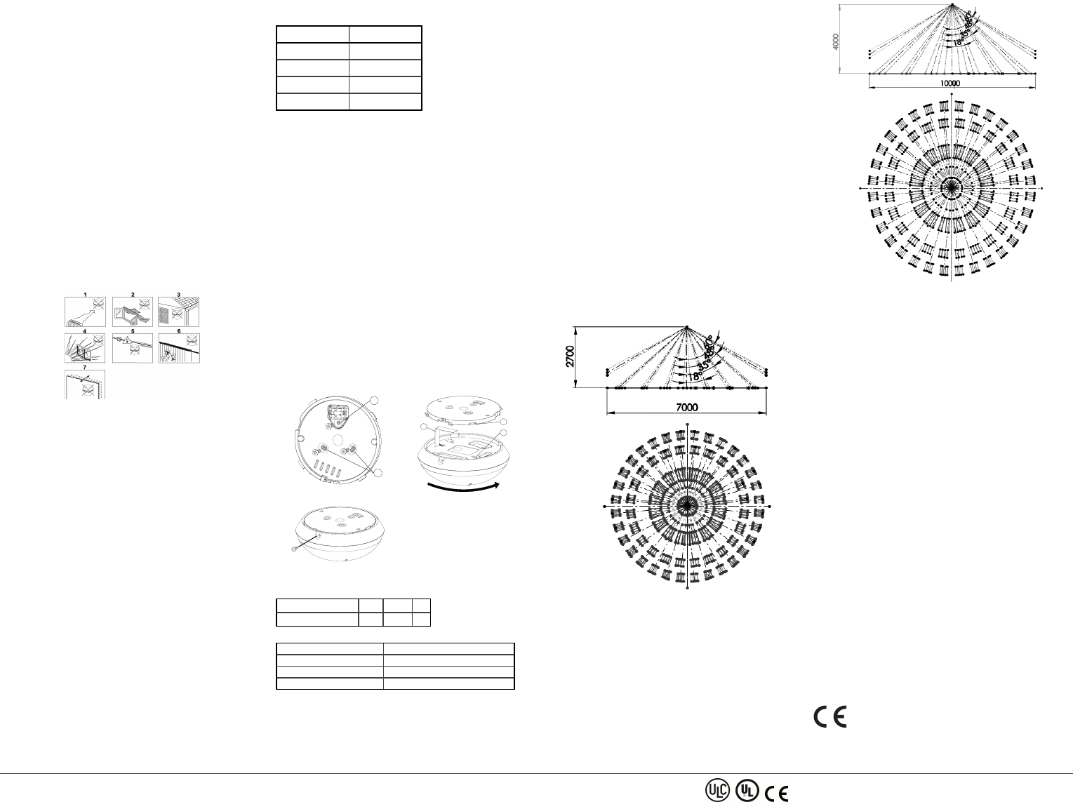
Figure 3. Consignes générales
1. Tenez l'appareil à l'écart de toute source de chaleur.
2. Ne l'exposez pas aux courants d'air.
3. Ne l'installez pas en extérieur.
4. Évitez l'exposition directe aux rayons du soleil.
5. N'installez pas l'appareil à proximité de lignes électriques à haute
tension.
6. N'installez pas l'appareil derrière une cloison.
7. Procédez au montage sur une surface stable solide.
ATTENTION! N'obstruez pas, totalement ou partiellement, le champ
de vision du détecteur.
ATTENTION! Pour des raisons de conformité aux normes d'ex-
position aux fréquences radio FCC et ISED Canada, le détecteur PIR
doit être distant d'au moins 20 cm de toute personne, e n conditions de
fonctionnement normales. Les antennes utilisées pour ce produit ne
doivent pas être positionnées dans un même espa ce, ni utilisées avec
une autre antenne ou émetteur.
REMARQUE: Le PGx862 Détecteur PIR sans fil de présence/sé-
curité pour plafond sera installé et utilisé dans un environnement non
dangereux où le niveau de pollution est inférieur à 2 et où il est exposé
à des tensions de catégorie II. L'équipement est conçu pour être
installé par du personnel de maintenance qualifié uniquement.
REMARQUE: Le PGx862 sera installé conformément à la norme UL
681, Standard for Installations and Classifications of burglar and Hol-
dup Alarm Systems.
Test de déplacement
Avant d'installer un appareil sans fil de manière définitive, montez l'ap-
pareil provisoirement et procédez à un test de déplacement. Exécutez
un test de déplacement dans la zone de couverture au moins une fois
par an pour vous assurer que le détecteur fonctionne correctement.
Après avoir inséré la pile ou fermé l'appareil, le détecteur entre auto-
matiquement dans une phase de stabilité pendant laquelle le voyant
ROUGE s'éclaire pendant 90 secondes. Marchez dans la zone. Le voy-
ant rouge s'éclaire à chaque fois que votre mouvement est détecté,
puis clignote trois fois. La couleur des trois clignotements indique la
puissance du signal reçu.
Le tableau ci-dessous indique la puissance du signal reçu.
Voyant Puissance du signal
Voyant vert clignotant FORT
Voyant orange clignotant BON
Voyant rouge clignotant FAIBLE
Aucun clignotement Pas de comm.
IMPORTANT! Seul un signal BON ou FORT est acceptable. Si vous
recevez un signal FAIBLE de l'appareil, changez-le d'emplacement et
recommencez les tests jusqu'à obtenir un signal BON ou FORT.
REMARQUE: Pour les installations conformes UL/ULC, seul un sig-
nal FORT est acceptable. Après l'installation, vérifiez le fonc-
tionnement du produit avec les centrales HSM2HOST9, HS2LCDRF
(P)9, HS2ICNRF(P)9, PG9920, WS900-19, and WS900-29. com-
patibles.
REMARQUE: Pour des instructions de positionnement détaillées, con-
sultez le manuel de référence de la centrale.
En mode de test de déplacement, quel que soit le statut de sélection des
voyants, le voyant s'éclaire à chaque fois qu'un mouvement est détecté.
Effectuez le test de déplacement dans toute la zone de couverture en
traversant d'un bout à l'autre la zone, dans les deux directions. Le voy-
ant rouge s'éclaire à chaque fois que votre mouvement est détecté,
puis le voyant d'indication de la puissance du signal s'éclaire. Au bout
de 15 minutes, le détecteur passe automatiquement en mode normal.
Montage de l'appareil
1. Marquez et percez deux trous dans la surface de montage. Si
vous installez l'autoprotection sur le détecteur, marquez et per-
cez un trou pour l'autoprotection et un trou pour une des autres
encoches disponibles.
2. Fixez le support à la surface de montage avec deux vis.
3. Alignez les pattes du support sur les encoches du détecteur et
faites tourner le détecteur dans le sens des aiguilles d'une
montre. Vérifiez qu'il est solidement fixé.
4. Fixez le détecteur au support avec la vis.
A
B
Figure 4. Fixation du support
D
E
C
Figure 5. Assemblage du détecteur
Figure 6. Fixation du détecteur
AAuto-protection
BOrifices pour vis du support
CLanguette d'isolation
DPattes du support
EEncoches du détecteur
Le tableau ci-dessous indique la distance de détection en fonction de
la hauteur de montage.
Hauteur 2m 3m 4m
Distance de détection 3,1m 3,75m 5m
Activité de la LED
Signaux lumineux Événement
Voyant rouge clignotant Stabilisation (préparation 90 sec)
Voyant rouge allumé 0,2 sec. Ouverture/fermeture autoprotection
Voyant rouge allumé 2 sec. Alerte intrusion
Affichage de la température et de la lumière
Pour savoir comment afficher sur la centrale adéquate la température
des zones, mesurée par le détecteur PGx862, consultez le guide d'in-
stallation de la centrale.
Caractéristiques techniques
GÉNÉRALES
Type de détecteur
Un capteur pyroélectrique fonctionnant dans une configuration
séparée double
OPTIQUE
Lentille
Lentille de type Fresnel.
Nombre de faisceaux: 72
Couverture max
Ø10 m/360° à la hauteur maximale d'installation de 4 m
CARACTÉRISTIQUES ÉLECTRIQUES
Alimentation: Type C
Pile interne
Pile Lithium 3V type CR-123A. Pour les installations certifiées UL,
utilisez uniquement une pile Panasonic ou GP
Capacité nominale de la pile: 1450mAh
Autonomie (utilisation courante)
1 an minimum. Dans le cadre d'une utilisation courante (mode sécur-
ité), 5 ans (non vérifié par UL).
Seuil pile faible: 2,4V
REMARQUE: L'incapacité à se connecter au réseau sans fil, ou une
qualité de réception sans fil inférieure à 20% peut réduire con-
sidérablement la durée de vie de la pile.
Test de la pile
Effectué immédiatement après l'insertion de la pile et régulièrement
toutes les quelques heures.
L'alimentation est de type C, conformément à la Documentation EN
50131-6 – Clause 6.
Consommation électrique
Consommation moyenne au repos 20µA, 150mA maximum (en trans-
mission)
Figure 7. Distribution du faisceau à 2,7 m
Figure 8. Distribution du faisceau à 4 m
CARACTÉRISTIQUES DE FONCTIONNEMENT
Période d'alarme: 2 secondes
COMMUNICATIONS SANS FIL
Fréquence
Europe et reste du monde: 433- 434 MHz, 868-869 MHz États-Unis:
912-919 MHz
REMARQUE: Seuls les appareils utilisant la bande de fréquences
915MHz sont certifiés UL/ULC.
Protocole de communication: PowerG
Supervision: Signaux espacés de 256 sec.
Alerte d'autoprotection
Émise en cas de sabotage et d'émission du message correspondant
jusqu'à ce que le commutateur d'auto-protection soit remis en place.
MONTAGE
Hauteur: 2 m à 4 m
Options d'installation: Surface du plafond
CONDITIONS ENVIRONNEMENTALES
Immunité aux fréquences radio
20V/m jusqu'à 1000MHz, 10V/m jusqu'à 2700MHz
Températures en fonctionnement
-10 °C à 55 °C.
REMARQUE: Fonctionnement conforme UL vérifié uniquement
entre 0 °C et 49 °C.
Températures en stockage
-20°C à 60°C
Humidité
Humidité relative moyenne jusqu'à environ 75% sans condensation.
Pe ndant 30 jours par an, l'humidité relative peut varier entre 85 % et
95 % sans condensation.
Pour les installations certifiées UL: 5% à 93% sans condensation
Dimensions
Taille (diamètre): 10.6 cm
Poids (avec pile): 110 g
Couleur: Blanc
RÉCEPTEURS COMPATIBLES
Cet appareil peut être utilisé avec les centrales et récepteurs DSC qui
utilisent la technologie PowerG.
REMARQUE: Seuls les appareils fonctionnant dans la bande de
fréquences 912-919MHz sont conformes UL/ULC.
Europe: CE/EN (EN50131-2-2 GRADE 2, CLASS II, EN50131-6
Type C) PG8862: 868 MHz PG4862: 433 MHz.
Selon les normes EN 50131-1, cet équipement peut être intégré dans les sys-
tèmes installés jusqu'à et y compris la classe environnementale II, niveau de
PGx862 Wireless ceiling PIR presence/security detector Installation Instructions ©2018 Tyco Security Products, Toronto, Canada www.dsc.com Tech. Support: 1-800-387-3630 4
sécurité 2. Royaume-Uni: Le PG886 2 convient pour l'u tilisation dans les sys-
tèmes installés pour se conformer à la norme PD6662 à la classe environ-
nementale 2 et de niveau 2 BS8243. Les dispositifs périphériques Power G
sont dotés d'une fonction de communication bidirectionnelle, offrant des
avantages supplémentaires comme décrit dans la brochure technique. Cette
fonction n'a pas été déclarée conforme aux besoins techniques respectifs et
doit, par conséquent, être exclue de la certification du produit.
Déclaration EU de Conformité Simplifiée
Le soussigné, Tyco Safety Products Canada Ltd déclare que le type d’équipe-
ment radioélectrique est conforme à la directive 2014/53/UE.
Le texte complet de la déclaration UE de conformité est disponible à l'adresse
internet suivante:
PG4862: http://dsc.com/pdf/1710001
PG8862: http://dsc.com/pdf/1710002
Bandes de fréquences Puissance maximale
433.04 MHz - 434.79 MHz 10 mW
868.0 MHz - 868.6 MHz 10 mW
868.7 MHz - 869.2 MHz 10 mW
Point de contact unique en Europe: Tyco Safety Products, Voltaweg 20,
6101 XK Echt, Pays-Bas.
PG9862/PG8862/PG4862 Información general
El PGx862 es un detector inalámbrico infrarrojo pasivo (PIR) de pres-
encia y seguridad inteligente para montaje en techo (modo selec-
cionado) que crea un área de cobertura de 360° para detectar el
movimiento de intrusos en áreas interiores.
El detector presenta las siguientes características.
lModo de detección de presencia: activar 15 minutos después de la
instalación (encendido).
lGracias a los indicadores de calidad del enlace incorporados, el
instalador no necesita acercarse físicamente al panel de control y
el tiempo de instalación se reduce.
lEl dispositivo es compatible con informes de temperatura y de
nivel de luz a sistemas de alarma compatibles, que admiten
sensores de temperatura y de luz.
lProtección contra manipulación.
lTecnología TDMA bidireccional Power-G de salto de frecuencias
de espectro amplio (FHSS).
lEl algoritmo patentado Advanced True Motion Recognition™ dis-
tingue entre el verdadero movimiento de un intruso y cualquier otra
perturbación que pueda causar falsas alarmas.
NOTA: En el caso de instalaciones UL, el detector se debe utilizar
únicamente con unidades de control homologadas por UL.
Leyenda
D
A
B
C
E
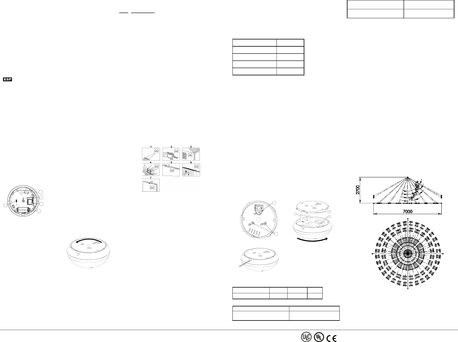
Figura 1. Vista interna
AProtección contra manipulación
BSensor de luz
CSensor piroeléctrico
DBatería
EIndicadores LED
Introducción o cambio de la batería
Si la batería ya está instalada, tire de la tira de activación que sobre-
sale de la parte posterior del detector.
1. Para separar el detector del soporte
de montaje, gire el soporte en el sen-
tido antihorario y extráigalo del
detector.
2. Inserte la batería teniendo en cuenta
la polaridad.
3. Alinee las pestañas del soporte con
las ranuras del detector y gire el
detector en el sentido horario, para
verificar que está bien sujeto.
Figura 2. Extracción del
soporte
NOTA: Se recomienda esperar aproximadamente 1 minuto después
de extraer la batería antes de introducir la nueva.
¡Cuidado! Riesgo de explosión si se sustituye la batería por un tipo ina-
decuado. La eliminación de baterías usadas se debe efectuar acorde
con las instrucciones del fabricante y de conformidad con las reglas y
reglamentaciones locales.
Registro
Para información sobre el procedimiento de registro, consulte el
manual de instalación del panel.
En el siguiente diagrama de flujo se provee una descripción general
del procedimiento:
Etapa Procedimiento
1 Para garantizar la aplicación de las etapas apropiadas, con-
sulte el manual de instalación del sistema de alarma en el
que el dispositivo está registrado.
2 Entre en la opción Registro de dispositivo por medio del
método especificado y elija la opción apropiada para
agregar el nuevo dispositivo.
3 Para registrar el dispositivo, introduzca la batería para
encenderlo hasta que se detecte el registro, o escriba el iden-
tificador (ID) del aparato.
4 Elija el número de la zona deseada.
5 Configure todos los parámetros del dispositivo que sean
necesarios.
6 Montar y probar el detector. Para obtener información
acerca de cómo probar el dispositivo, consulte Prueba de
recorrido. Consulte también el manual de instalación de sis-
temas de alarma, para comprobar si el dispositivo está regis-
trado o para ver otros procedimientos de prueba que sean
necesarios.
NOTA: Si el detector ya está registrado, puede configurar sus pará-
metros mediante la programación del sistema. Para más información
sobre los parámetros del dispositivo, consulte el manual de instalación
de alarmas.
NOTA: Al registrar el detector PGx862 en los paneles inalámbricos
(WP80XX) con la versión 19.4 o anteriores, el detector se registrará
como detector de movimiento, ID 120-xxxx y se etiquetará como
‘Motion Sens’ en el panel.
Consejos para la instalación
Utilizar la siguiente información como guía para localizar un lugar de
montaje adecuado.
Figura 3. Lineamientos generales
1. Mantener alejado de fuentes de calor.
2. No exponer a corrientes de aire.
3. No instalar al aire libre.
4. Evitar la luz solar directa.
5. No instalar cerca de líneas eléctricas de alta tensión.
6. No instalar detrás de particiones.
7. Montar sobre una superficie estable y sólida.
¡ADVERTENCIA! No obstaculice el campo de visión del detector de
forma parcial ni total.
¡ADVERTENCIA! Para cumplir con los requisitos de cumplimiento de
normas de exposición de FCC e ISED Canada RF, el panel de control
se debe ubicar a una distancia de al menos 20 cm de todas las per-
sonas durante el funcionamiento normal. Las antenas que se utilizan
para este producto no se deben instalar ni utilizar junto otra antena u
otro transmisor.
NOTA: El PGx862 [[[Undefined variable Vari-
ableSetsSpanish/General.ProductDesc]]] se debe instalar y utilizar en
un entorno que provea el nivel de contaminación máximo de 2 y la cat-
egoría de sobretensión II en LUGARES NO PELIGROSOS. El equipo
está diseñado para ser instalado solo por personal de servicio capa-
citado.
NOTA: PGx862 se debe instalar de conformidad con la Norma de
Instalación y Clasificación de Sistemas de Alarma de robo y asalto,
UL 681.
Prueba de recorrido
Antes del montaje permanente de cualquier dispositivo inalámbrico,
móntelo temporalmente y haga una prueba de recorrido. Haga una
prueba de recorrido del detector, por lo menos una vez al año, para
asegurarse de que el detector funciona correctamente.
Después de introducir la batería o de cerrar el dispositivo, el detector
entra automáticamente en un periodo de estabilidad cuando el indic-
ador LED parpadea en ROJO durante 90 segundos. Al efectuar la
prueba de recorrido del área de cobertura, cada vez que se detecte su
movimiento, el indicador LED se enciende en rojo, seguido de tres des-
tellos. El color de los tres destellos del indicador LED indican la poten-
cia de la señal recibida.
En la siguiente tabla se indica la potencia de la señal recibida.
Respuesta del indicador LED Potencia de señal
El indicador LED verde parpadea ALTA
El indicador LED naranja parpadea BUENA
El indicador LED verde parpadea BAJA
Sin parpadeo Sin comunicación
¡IMPORTANTE! Las únicas potencias de señal aceptables son
BUENA o ALTA. Si recibe una señal DÉBIL del dispositivo,
reubíquelo y vuelva a probar hasta que reciba una potencia de señal
BUENA o ALTA.
NOTA: En instalaciones de UL/ULC, solo se admite una potencia de
señal ALTA. Después de la instalación, verifique la funcionalidad del
producto junto con los paneles de control compatibles HSM2HOST9,
HS2LCDRF(P) 9, HS2ICNRF(P)9, PG9920, WS900-19, and WS900-29.
NOTA: Para ver instrucciones de colocación, consulte el manual de
referencia del panel de control.
En el modo de prueba de recorrido, sea cual sea el estado de selec-
ción del indicador LED, este se enciende cada vez que se detecta
movimiento. Haga una prueba de recorrido del área de cobertura cam-
inando por el extremo más lejano del patrón de cobertura en ambas
direcciones. Cada vez que se detecte su movimiento, el indicador LED
se enciende en rojo, seguido de una indicación de potencia de señal
del indicador LED. Al cabo de 15 minutos, el detector entra automát-
icamente en el modo normal.
Montaje del dispositivo
1. Marque y taladre dos orificios en la superficie de montaje. Si
instala en el detector una protección contra manipulación,
marque y perfore un orificio para dicha protección y un orificio
para una de las otras ranuras disponibles.
2. Fije el soporte a la superficie de montaje con los dos tornillos.
3. Alinee las pestañas del soporte con las ranuras del detector y
gire el detector en el sentido horario. Verifique que esté bien
sujeto.
4. Con el tornillo, sujete el detector al soporte.
A
B
Figura 4. Sujeción del soporte
D
E
C
Figura 5. Colocación del detector
Figura 6. Sujeción del detector
AProtección contra alteración
BRanuras de tornillos del soporte
CBanda de aislamiento
DLengüetas del soporte
ERanuras del detector
En la siguiente tabla se indica la distancia de detección en relación
con la altura de montaje.
Altura 2 metros 3 metros 4 metros
Distancia de detección 3,1 metros 3,75 metros 5 metros
Utilización del LED
Indicaciones del LED Evento
El indicador LED verde parpadea Estabilización (90 segundos de
calentamiento)
Indicador LED rojo encendido dur-
ante 0.2 segundos
Abrir o cerrar protección con-
tra manipulación
Indicador LED rojo encendido dur-
ante 2 segundos Alarma de intruso
Indicación de temperatura y luz
Para obtener instrucciones sobre la indicación de la temperatura de
zonas en el panel correcto según las mediciones del PGx862, consulte
la guía de instalación del panel.
Especificaciones
GENERAL
Tipo de detector
Un sensor piroeléctrico que funciona en una configuración dual sep-
arada
ÓPTICAS
Información sobre la lente
Lente de tipo Fresnel.
Cantidad de haces: 72
Cobertura máxima
Ø10 m/360° a una altura de instalación máxima de 4 metros
ELÉCTRICAS
Fuente de alimentación: Tipo C
Batería interna
Batería de litio de 3 voltios, CR-123A. En el caso de instalaciones UL,
utilizar solo Panasonic y GP
Capacidad nominal de la batería: 1450 mAh
Vida útil de la batería, en uso normal
Como mínimo 1 año. Para uso típico (modo de seguridad), 5 años (no
verificado por UL).
Umbral de batería baja: 2,4 voltios
NOTA: La incapacidad de conectarse con una red inalámbrica o una
calidad de enlace inalámbrico no superior al 20% podrían reducir sig-
nificativamente la vida útil prevista de la batería.
Prueba de potencia de batería
Se efectúa inmediatamente después de introducir la batería y per-
iódicamente cada tantas horas.
La fuente de alimentación es del tipo C, de conformidad con la Docu-
mentación EN 50131-6, cláusula 6.
Consumo actual
Corriente de reposo promedio 20 μA, máxima 150 mA (durante la
transmisión)
Figura 7. Distribución de haz a 2,7 metros
PGx862 Wireless ceiling PIR presence/security detector Installation Instructions ©2018 Tyco Security Products, Toronto, Canada www.dsc.com Tech. Support: 1-800-387-3630 5
Figura 8. Distribución de haz a 4 metros
FUNCIONAL
Periodo de alarma: 2 segundos
INALÁMBRICO
Frecuencia
Europa y resto del mundo: 433 a 434 MHz, 868 a 869 MHz EEUU:
912 a 919 MHz
NOTA: Solo dispositivos que funcionan en la banda de 915 MHz
están homologados por UL/ULC.
Protocolo de comunicaciones: PowerG
Supervisión: Señalización a intervalos de 256 segundos
Alerta de manipulación
Se notifica durante un evento de manipulación y en cada mensaje sub-
siguiente, hasta que el interruptor de seguridad se restablezca.
MONTAJE
Peso: 2 a 4 metros
Opciones de instalación: Superficie del techo
AMBIENTALES
Inmunidad a RF
20 V/m hasta 1000 MHz, 10 V/m hasta 2700 MHz
Temperaturas de funcionamiento
-10°C a 55°C.
NOTA: Margen de operación verificado por UL, 0 °C a 49°C única-
mente.
Temperaturas de almacenamiento
-20 °C a 60 °C
Humedad
Humedad relativa promedio de hasta un 75%, sin condensación. Dur-
ante 30 días al año, la humedad relativa puede variar entre el 85% y el
95%, sin condensación.
En el caso de instalaciones UL: 5% a 93% sin condensación
FÍSICAS
Tamaño (diámetro): 10.6 cm
Peso (incluida la batería): 110 gramos
Color: Blanco
RECEPTORES COMPATIBLES
Este dispositivo se puede utilizar con paneles y receptores DSC que
utilizan la tecnología PowerG.
NOTA: Solo dispositivos que funcionan en la banda de 912 a 919
MHz están homologados por UL/ULC.
Europa: CE/EN (EN50131-2-2 GRADE 2, CLASS II, EN50131-6
Typo C) PG8862: 868 MHz PG4862: 433 MHz.
De acuerdo con las normas EN 50131-1, este equipo puede ser aplicado en
sistemas instalados hasta e incluyendo el Grado 2 de Seguridad, Clase
ambiental II. Reino Unido: El modelo PG8862 es adecuado para uso en sis-
temas instalados para cumplir con PD6662 en el Grado 2 y Clase ambiental 2
BS8243. Los dispositivos periféricos Power G tienen funcionalidad de comu-
nicación de dos vías, lo que proporciona ventajas adicionales como se
describen en el folleto técnico. No se ha probado que estas funciones
cumplan con los requisitos técnicos correspondientes y, por lo tanto, deber-
ían considerarse fuera del alcance de la certificación del producto.
Declaración UE de Conformidad Simplificada
Por la presente, Tyco Safety Products Canada Ltd declara que el typo de
equipo radioeléctrico es conforme con la Directiva 2014/53/UE.
El texto completo de la declaración UE de conformidad está disponible en la
dirección Internet siguiente:
PG4862: http://dsc.com/pdf/1710001
PG8862: http://dsc.com/pdf/1710002
Bandes d e freceuncia Potencia máxima
433.04 MHz - 434.79 MHz 10 mW
868.0 MHz - 868.6 MHz 10 mW
868.7 MHz - 869.2 MHz 10 mW
Punto de contacto único en Europa: Tyco Safety Products, Voltaweg 20,
6101 XK Echt, Holanda.
PG9862/PG8862/PG4862 Visão geral
A PGx862 é um detector inteligente de presença/segurança PIR de
teto sem fio (modo selecionado) que cria uma área de cobertura de
360 ° para detectar o movimento de intrusos em áreas internas.
O detector tem os seguintes recursos.
lModo de detecção de presença – 15 minutos ativos após instalação
(inicialização).
lIndicadores de qualidade de conexão embutidos eliminam a
necessidade de um instalador para se aproximar fisicamente do
painel de controle e reduz o tempo de instalação.
lO dispositivo suporta avisos de temperatura e nível de luz para sis-
temas de alarme compatíveis que aceitem sensores de tem-
peratura e luz.
lProteção contra violação.
lTecnologia FHSS-TDMA de Espectro de Alastramento com
Mudança de Frequência de duas vias Power-G.
lO algoritmo avançado True Motion Recognition™ (patenteado)
diferencia os verdadeiros movimentos de um invasor e quaisquer
outros distúrbios que possam causar alarmes falsos.
OBS.: Para instalações de UL: o detector só deve ser usado com unid-
ades de controle listada em UL.
Legenda
D
A
B
C
E
Figura 1. Visão interna
AProteção contra violação
BSensor de luz
CSensor de fogo
DBateria
ELEDs
Inserir ou trocar a pilha
Se a bateria já estiver instalada, puxe a faixa de ativação que se
encontra protuberante na traseira do detector.
1. Para separar o detector do suporte
de montagem, gire o suporte em sen-
tido anti-horário e puxe-o do
detector.
2. Insira a bateria levando em conta a
polaridade.
3. Alinhe as roscas do suporte aos
encaixes do detector e gire o
detector em sentido horário para cer-
tificar-se de que ele está firmemente
preso.
Figura 2. Remoção do
suporte
OBS.: Recomenda-se esperar cerca de 1 minuto depois de remover a
pilha antes de inserir a nova pilha.
Cuidado! Risco de explosão se a bateria for trocada por uma de um
tipo incorreto. Descarte as baterias usadas de acordo com as
instruções do fabricante e com as regras e normas locais.
Registro
Consulte o manual de instalação do painel para aprender o pro-
cedimento de registro.
Uma descrição geral do procedimento é fornecida no fluxograma a
seguir:
Etapa Procedimento
1 Consulte o manual de instalação do sistema de alarme ao
qual o dispositivo está sendo registrado para garantir que as
etapas adequadas sejam feitas.
2 Entre na opção Registro de Dispositivo pelo método espe-
cificado e selecione a opção apropriada para adicionar um
novo dispositivo.
3 Registre o dispositivo inserindo a bateria para ligar o dis-
positivo até que o registro seja detectado ou insira o ID do
dispositivo.
4 Selecione o nº da zona desejada.
5 Configure os parâmetros necessários do dispositivo.
6 Monte e teste o detector. Consulte Teste de caminhada para
obter mais informações sobre como testar o dispositivo.
Além disso, consulte o manual de instalação dos sistemas de
alarme nos quais o dispositivo foi registrado para ver outros
procedimentos de teste que são necessários.
OBS.: Se o detector já estiver registrado, você pode configurar os
parâmetros do detector pela programação do sistema. Consulte o
manual de instalação dos sistemas de alarme para obter mais inform-
ações sobre os parâmetros do dispositivo.
OBS.: ao registrar o detector PGx862 a painéis sem fio (WP80XX)
com a versão 19.4 ou uma anterior, o detector será registrado como
um detector de movimento, ID 120-xxxx, e identificado como ‘Sensor
de mov’ no painel.
Dicas de Instalação
Use as seguintes dicas como um guia para localizar um local
adequado para a montagem.
Figura 3. Orientações gerais
1. Mantenha longe de fontes de calor.
2. Não exponha a saídas de ar.
3. Não instale em ambientes externos.
4. Evite exposição direta ao sol.
5. Não instale perto de redes elétricas de alta tensão.
6. Não instale atrás de nenhuma partição.
7. Monte em uma superfície sólida estável.
AVISO! Não obscureça parcialmente nem totalmente o campo de
visão do detector.
AVISO! A fim de obedecer os requisitos de conformidade de
exposição do FCC e ISED Canada RF, o detector PIR deve estar em
uma distância de ao menos 20 cm de qualquer pessoa durante a oper-
ação normal. As antenas usadas para este produto não podem estar
colocalizadas ou ser operadas em conjunto com qualquer outra antena
ou transmissor.
OBS.: O PGx862 [[[Undefined variable Vari-
ableSetsPortuguese/General.ProductDesc]]] deve ser instalado e
usado dentro de um ambiente que forneça o grau máximo de poluição
2 e sobretensão de categoria II, LOCAIS NÃO PERIGOSOS. O
equipamento foi projetado para ser instalado apenas pelo pessoal qual-
ificado de serviço.
OBS.: O PGx862 deve ser instalado de acordo com as normas de
instalação e classificação de sistemas de alarme contra ladrões e
assaltos, UL 681.
Teste de caminhada
Antes de montar permanentemente qualquer dispositivo sem fio, monte
temporariamente o dispositivo e realize um teste de caminhada. Real-
ize um teste de caminhada da área de cobertura pelo menos uma vez
ao ano para garantir que o detector está funcionando corretamente.
Após colocar a bateria ou fechar o dispositivo, o detector auto-
maticamente entrará em um período de estabilidade em que o LED
VERMELHO piscará por 90 segundos. Faça um teste de caminhada
pela área de cobertura; o LED vermelho piscará cada vez que seu
movimento for detectado seguido por três piscadas de LED. A cor das
três piscadas de LED indica a força do sinal recebido.
A tabela a seguir indica a força do sinal recebido.
Reposta do LED Intensidade do sinal
LED verde pisca FORTE
LED laranja pisca BOM
LED vermelho pisca RUIM
Nada pisca Sem comunicação
IMPORTANTE! Somente são aceitos intensidades de sinal BOA ou
FORTE. Se você receber um sinal RUIM do dispositivo, reposicione-o
e teste novamente até receber um sinal BOM ou FORTE.
OBS.: Para instalações UL/ULC, apenas o nível de sinal FORTE é
aceitável. Após a instalação, verifique a funcionalidade do produto em
conjunto com os painéis de controle compatíveis HSM2HOST9,
HS2LCDRF(P) 9, HS2ICNRF(P)9, PG9920, WS900-19, and WS900-29.
OBS.: Para obter instruções detalhadas de colocação, consulte o Guia
de referência do painel de controle.
No modo teste de caminhada, independentemente do status de Selação
do LED, o LED acende quando da detecção de qualquer movimento.
Faça o teste de caminhada pela área de cobertura caminhando através
do limite mais distante do padrão de cobertura em ambos os sentidos.
O LED vermelho acende cada vez que seu movimento for detectado
seguido por indicação de força do sinal de LED constante. Depois de
15 minutos, o detector entra automaticamente no modo normal.
Montagem do dispositivo
1. Marque e perfure dois furos na superfície de montagem. Se
você instalar a proteção contra violação no detector, marque e
perfure um furo para a proteção contra violação e um furo para
um dos outros encaixes disponíveis.
2. Fixe o suporte à superfície de montagem usando os dois par-
afusos.
3. Alinhe as roscas do suporte aos encaixes do detector e gire o
detector em sentido horário. Certifique-se de que está bem
preso.
4. Fixe o detector ao suporte com o parafuso.
A
B
Figura 4. Fixação do suporte
D
E
C
Figura 5. Colocação do detector
Figura 6. Fixação do detector
AProteção contra violação
BEncaixes de parafuso do
suporte
CFaixa de isolamento
DRoscas do suporte
EEncaixes do detector
A seguinte tabela resume a distância de detecção em relação à altura
da montagem.
Altura 2 m 3 m 4 m
Distância de detecção 3,1 m 3,75 m 5 m
Operação do LED
Indicações do LED Evento
LED vermelho pisca Estabilização (aquecimento de 90
segundos)
LED vermelho em 0,2 segun-
dos Abrir/fechar violação
LED vermelho em 2 segun- Alarme de intruso
PGx862 Wireless ceiling PIR presence/security detector Installation Instructions ©2018 Tyco Security Products, Toronto, Canada www.dsc.com Tech. Support: 1-800-387-3630 6
dos
Visor de temperatura e luz
Para ver instruções sobre como exibir a temperatura de zonas no
painel correto, como medida pelo PGx862, consulte o guia de
instalação do painel.
Especificações
GERAL
Tipo de detector
Um sensor piroelétrico que funciona em uma configuração dual sep-
arada
ÓTICAS
Dados da lente
Lentes de tipo Fresnel.
Número de feixes: 72
Cobertura máx.
Ø10 m/360° na altura máxima de instalação de 4 m
ELÉTRICAS
Fonte de alimentação: Tipo C
Bateria interna
Pilha de lítio de 3 V, tipo CR- 123A. Para instalações de UL, use
apenas Panasonic e GP
Capacidade nominal da pilha: 1450 mAh
Vida útil da bateria (uso típico)
Mínimo de 1 ano. Para uso normal (modo de segurança), 5 anos (não
verificado pelo UL).
Limite de bateria fraca: 2,4 V
OBS.: A incapacidade de se conectar a uma rede sem fio ou a qual-
idade de uma conexão sem fio inferior a 20% podem diminuir sig-
nificativamente a expectativa de vida da pilha.
Teste de energia da pilha
Realizado logo após a introdução da pilha e periodicamente em inter-
valos de algumas horas.
A fonte de alimentação é do tipo C, de acordo com a Documentação
EN 50131-6 — Cláusula 6.
Consumo de corrente
20μA quiescente médio, máximo 150 mA (durante transmissão)
Figura 7. Distribuidor de feixe a 2,7 m
Figura 8. Distribuidor de feixe a 4 m
FUNCIONAIS
Tempo de alarme: 2 segundos
SEM FIO
Frequência
Europa e resto do mundo: 433-434 MHz, 868-869 MHz EUA: 912-
919 MHz
OBS.: Apenas os dispositivos na faixa de frequência de 915 MHz são
lista dos pela UL/ULC.
Protocolo de comunicação: PowerG
Supervisão: Sinalização em intervalos de 256 seg
Alerta de violação
Comunicado quando ocorre uma violação e em qualquer mensagem
subsequente até que a chave de violação seja restaurada.
INSTALAÇÃO
Altura: 2 m a 4 m
Opções de instalação: Superfície do teto
AMBIENTAIS
Imunidade a RF
De 20 V/m até 1000 MHz, de 10 V/m até 2700 MHz
Temperaturas operacionais
-10°C a 55°C (14°F a 131°F).
OBS.: A UL verificou somente a operação acima da faixa de 0°C a
49°C.
Temperaturas de armazenamento
-20°C a 60°C (de - 4°Fa 140°F)
Umidade
Umidade relativa média de aproximadamente 75% sem condensação.
Por 30 dias por ano, a umidade relativa pode variar de 85% a 95%
sem condensação.
Para instalações de UL: 5% a 93% sem condensação
FÍSICAS
Tamanho (diâmetro): 10.6 cm
Peso (com bateria): 110 g (3,88 oz)
Cor: Branca
RECEPTORES COMPATÍVEIS
Este dispositivo pode ser usado com painéis e receptores DSC que
usem a tecnologia PowerG.
OBS.: Apenas os dispositivos operando na faixa de 912-919 MHz são
lista dos pela UL/ULC.
Europa: CE/EN (EN50131-2-2 GRADE 2, CLASS II, EN50131-6
Tipo C) PG8862: 868 MHz PG4862: 433 MHz.
Conforme a EN 5 0131-1, este equipamento pode ser aplicado em sistemas
instalados até e incluindo o Grau 2 de Segurança, Classe II Ambiental. RU: O
PG8862 é apropriado para uso em sistemas instalados em conformidade com
PD6662 no Grau 2 e classe ambiental 2 BS8243. O periférico PowerG tem
uma funcionalidade de comunicação em 2 vias, providenciando benefícios
adicionais descritos na brochura técnica. Esta funcionalidade não foi testada
para estar conforme os respectivos requisitos técnicos e deve, portanto, ser
considerada fora do âmbito da certificação do produto.
Declaração UE de Comformidade Simplificada
O(a) abaixo assinado(a), Tyco Safety Products Canada Ltd declara que o
presente tipo de equipamento de rádio está em confo rmidade com a Diretiv a
2014/53/UE.
O texto integral da declaração de conformidade está disponível no seguinte
endereço de Internet:
PG4862: http://dsc.com/pdf/1710001
PG8862: http://dsc.com/pdf/1710002
Bandes d e frequências Potência máxima
433.04 MHz - 434.79 MHz 10 mW
868.0 MHz - 868.6 MHz 10 mW
868.7 MHz - 869.2 MHz 10 mW
Ponto único de contato na Europa: Tyco Safety Products, Voltaweg 20, 6101
XK Echt, Holanda.
D-307205 Rev 1 (05/18)
29010048R001