Tyco Safety Canada 18PG9872 Smart Wireless Ceiling PIR Presence/Security Detector User Manual My
Digital Security Controls Ltd. Smart Wireless Ceiling PIR Presence/Security Detector My
UserManual.wiki
>
Tyco Safety Canada
>
18PG9872 User Manual
Users Manual
Navigation menu
Upload a User Manual
Namespaces
Wiki Guide
HTML
PDF
Info
Views
User Manual
Discussion / Help
Navigation
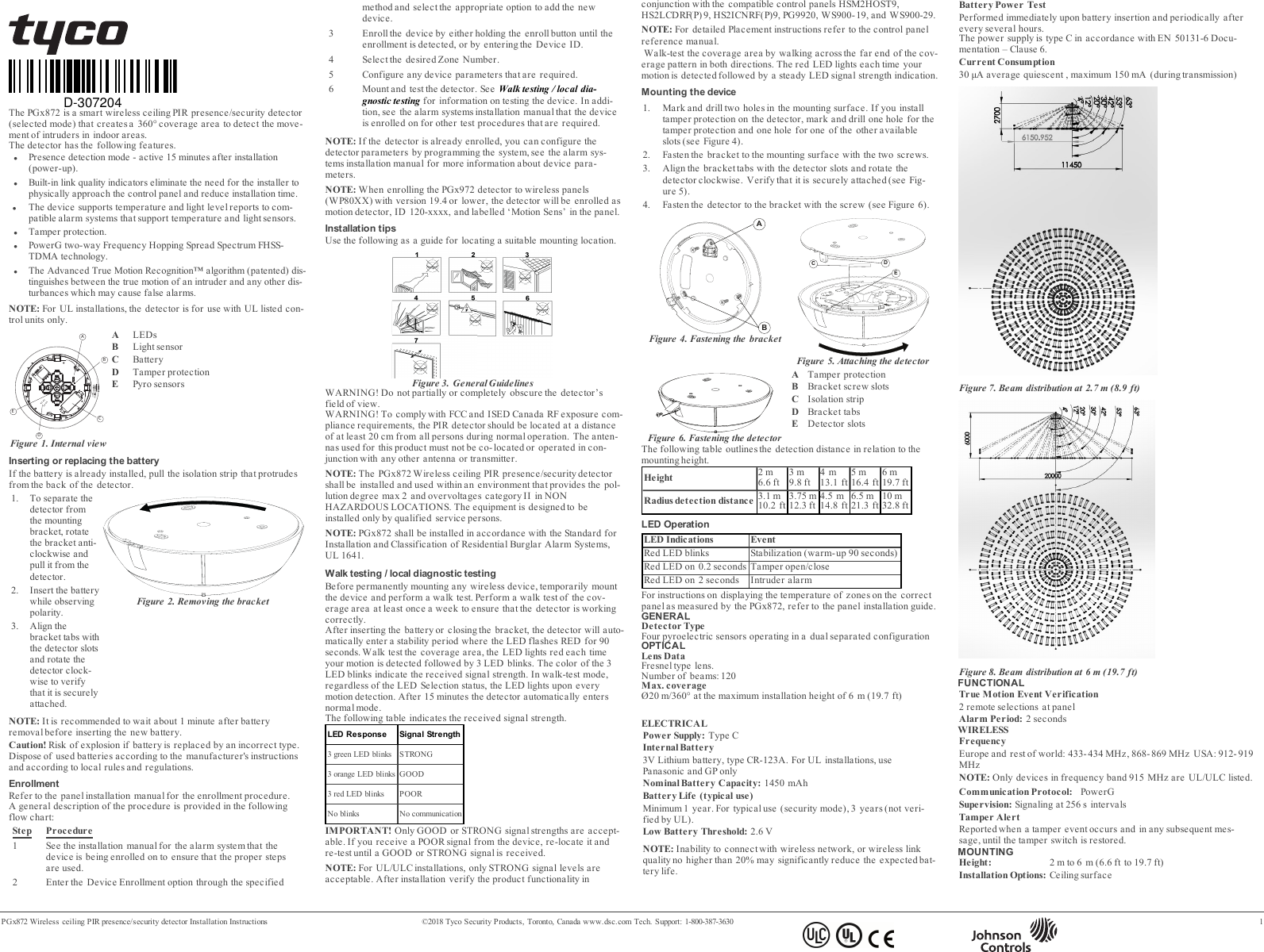
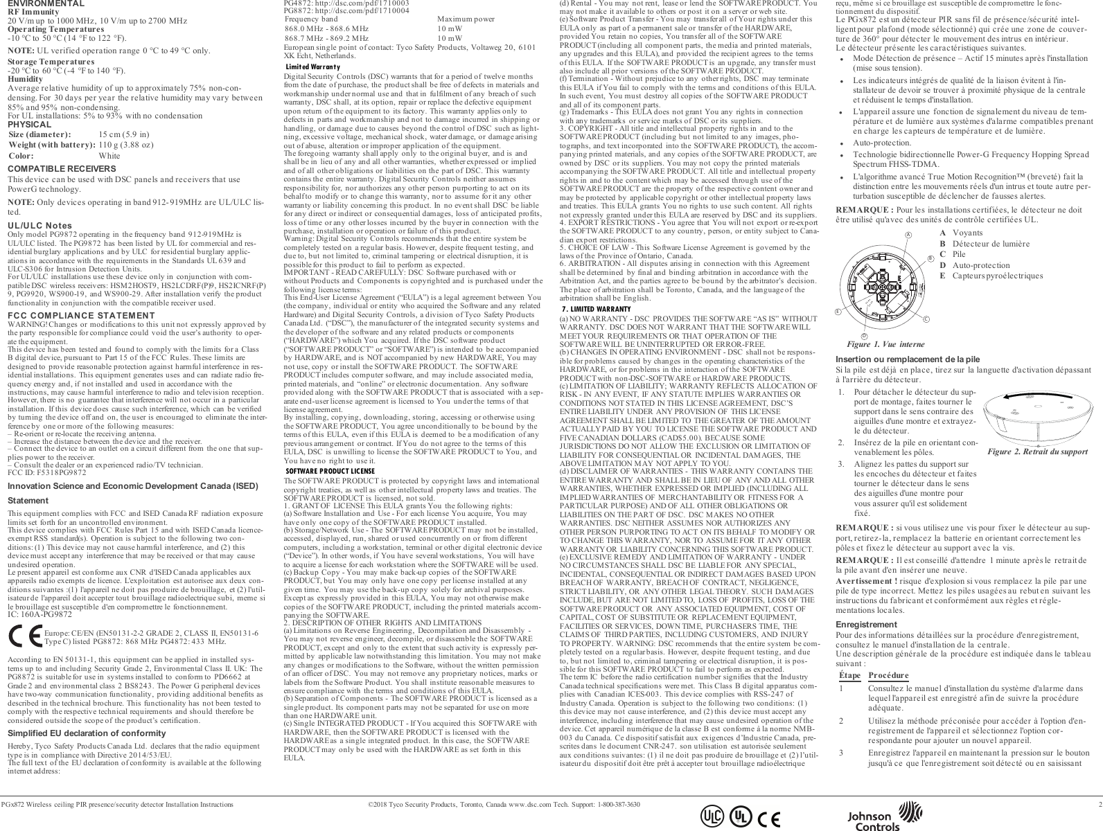
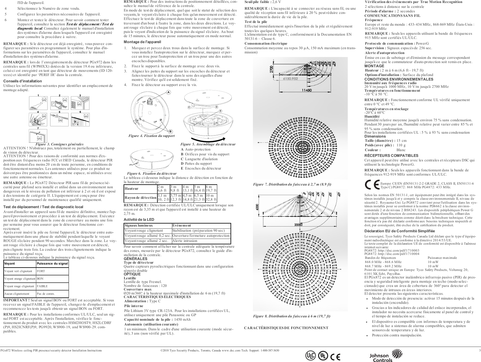
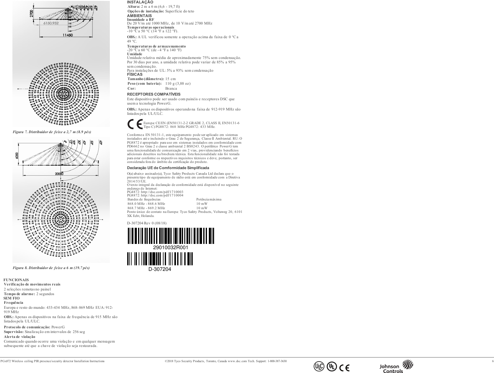
![PGx872 Wireless ceiling PIR presence/security detector Installation Instructions ©2018 Tyco Security Products, Toronto, Canada www.dsc.com Tech. Support: 1-800-387-3630 4lTecnología TDMA bidireccional Power-G de salto de frecuenciasde espectro amplio (FHSS).lEl algoritmo patentado Advanced True Motion Recognition™ dis-tingue entre el verdadero movimiento de un intruso y cualquier otraperturbación que pueda causar falsas alarmas.NOTA: En el caso de instalaciones UL, el detector se debe utilizarúnicamente con unidades de control homologadas por UL.ABCDEFigura 1. Vista internaAIndicadores LEDBSensor de luzCBateríaDProtección contra manipulaciónESe nsore s piroeléctricosIntroducción o cambio de la bateríaSi la batería ya está instalada, tire de la tira de activación que sobre-sale de la parte posterior del detector.1. Para separar el detector delsoporte de montaje, gire el soporteen el sentido antihorario y extrái-galo del detector.2. Inserte la batería teniendo encuenta la polaridad.3. Alinee las pestañas del soporte conlas ranuras del detector y gire eldetector en el sentido horario, paraverificar que está bien sujeto.Figura 2. Extracción delsoporteNOTA: Si se usa un tornillo para fijar el detector al soporte, quite eltornillo, cambie la batería manteniendo la polaridad y fije el detectoral soporte usando el tornillo.NOTA: Se recomienda esperar aproximadamente 1 minuto despuésde extraer la batería antes de introducir la nueva.¡Cuidado! Riesgo de explosión si se sustituye la batería por un tipo ina-decuado. La eliminación de baterías usadas se debe efectuar acordecon las instrucciones del fabricante y de conformidad con las reglas yreglamentaciones locales.RegistroPara información sobre el procedimiento de registro, consulte elmanual de instalación del panel.En el siguiente diagrama de flujo se provee una descripción generaldel procedimiento:Etapa Procedimiento1 Para garantizar la aplicación de las etapas apropiadas, con-sulte el manual de instalación del sistema de alarma en elque el dispositivo está registrado.2 Entre en la opción Registro de dispositivo por medio delmétodo especificado y elija la opción apropiada paraagregar el nuevo dispositivo.3 Para registrar el dispositivo, mantenga presionado el botónde registro hasta que se detecte el registro, o escriba el iden-tificador (ID) del aparato.4 Elija el número de la zona deseada.5 Configure todos los parámetros del dispositivo que seannecesarios.6 Montar y probar el detector. Para obtener informaciónacerca de cómo probar el dispositivo, consulte Prueba derecorrido / Prueba de diagnóstico local. Consulte también elmanual de instalación de sistemas de alarma, para com-probar si el dispositivo está registrado o para ver otros pro-cedimientos de prueba que sean necesarios.NOTA: Si el detector ya está registrado, puede configurar sus pará-metros mediante la programación del sistema. Para más informaciónsobre los parámetros del dispositivo, consulte el manual de instalaciónde alarmas.NOTA: Al registrar el detector PGx972 en los paneles inalámbricos(WP80XX) con la versión 19.4 o anteriores, el detector se registrarácomo detector de movimiento, ID 120-xxxx y se etiquetará como‘Motion Sens’ en el panel.Consejos para la instalaciónUtilizar la siguiente información como guía para localizar un lugar demontaje adecuado.Figura 3. Lineamientos generales¡ADVERTENCIA! No obstaculice el campo de visión del detector deforma parcial ni total.¡ADVERTENCIA! Para cumplir con los requisitos de cumplimiento denormas de exposición de FCC e ISED Canada RF, el panel de controlse debe ubicar a una distancia de al menos 20 cm de todas las per-sonas durante el funcionamiento normal. Las antenas que se utilizanpara este producto no se deben instalar ni utilizar junto otra antena uotro transmisor.NOTA: El PGx872 [[[Undefined variable Vari-ableSetsSpanish/General.ProductDesc]]] se debe instalar y utilizar enun entorno que provea el nivel de contaminación máximo de 2 y la cat-egoría de sobretensión II en LUGARES NO PELIGROSOS. El equipoestá diseñado para ser instalado solo por personal de servicio capa-citado.Prueba de recorrido / Prueba de diagnóstico localAntes del montaje permanente de cualquier dispositivo inalámbrico,móntelo temporalmente y haga una prueba de recorrido. Haga unaprueba de recorrido del detector, por lo menos una vez al semana,para asegurarse de que el detector funciona correctamente.Después de introducir la batería o de cerrar el dispositivo, el detectorentra automáticamente en un periodo de estabilidad cuando el indic-ador LED parpadea en ROJO durante 90 segundos. Al efectuar laprueba de recorrido del área de cobertura, cada vez que se detecte sumovimiento, el indicador LED se enciende en rojo, seguido de tres des-tellos. El color de los tres destellos del indicador LED indican la poten-cia de la señal recibida.En la siguiente tabla se indica la potencia de la señal recibida.Respuesta del indicador LED Potencia de señalEl indicador LED verde parpadea ALTAEl indicador LED naranja parpadea BUENAEl indicador LED verde parpadea BAJASin parpadeo Sin comunicación¡IMPORTANTE! Las únicas potencias de señal aceptables sonBUENA o ALTA. Si recibe una señal DÉBIL del dispositivo,reubíquelo y vuelva a probar hasta que reciba una potencia de señalBUENA o ALTA.NOTA: En instalaciones de UL/ULC, solo se admite una potencia deseñal ALTA. Después de la instalación, verifique la funcionalidad delproducto junto con los paneles de control compatibles HSM2HOST9,HS2LCDRF(P) 9, HS2ICNRF(P)9, PG9920, WS900-19, and WS900-29.NOTA: Para ver instrucciones de colocación, consulte el manual dereferencia del panel de control.En el modo de prueba de recorrido, sea cual sea el estado de selec-ción del indicador LED, este se enciende cada vez que se detectamovimiento. Haga una prueba de recorrido del área de cobertura cam-inando por el extremo más lejano del patrón de cobertura en ambasdirecciones. Cada vez que se detecte su movimiento, el indicador LEDse enciende en rojo, seguido de una indicación de potencia de señaldel indicador LED. Al cabo de 15 minutos, el detector entra automát-icamente en el modo normal.Montaje del dispositivo1. Marque y taladre dos orificios en la superficie de montaje. Siinstala en el detector una protección contra manipulación,marque y perfore un orificio para dicha protección y un orificiopara una de las otras ranuras disponibles.2. Fije el soporte a la superficie de montaje con los dos tornillos.3. Alinee las pestañas del soporte con las ranuras del detector ygire el detector en el sentido horario. Verifique que esté biensujeto.4. Con el tornillo, sujete el detector al soporte.ABFigura 4. Sujeción del soporteDECFigura 5. Colocación del detectorFigura 6. Sujeción del detectorAProtección contra alteraciónBRanuras de tornillos del soporteCBanda de aislamientoDLengüetas del soporteERanuras del detectorEn la siguiente tabla se indica la distancia de detección en relacióncon la altura de montaje.Altura 2 metros6.6 ft 3 metros9.8ft 4 metros13.1ft 5 metros16.4 ft6 met-ros19.7 ftDistancia de detec-ción3,1 met-ros10,2 ft3,75 met-ros12,3 ft4,5 met-ros14,8 ft6,5 met-ros21,3 ft10 met-ros32,8 ftNOTA:Detección verificada por UL/ULC solo en un radio de 3,35metros, cuando el dispositivo está instalado a una altura de 2,75 met-ros.Utilización del LEDIndicaciones del LED EventoEl indicador LED verde parpadea Estabilización (90 segundos decalentamiento)Indicador LED rojo encendido dur-ante 0.2 segundosAbrir o cerrar protección con-tra manipulaciónIndicador LED rojo encendido dur-ante 2 segundos Alarma de intrusoPara obtener instrucciones sobre la indicación de la temperatura dezonas en el panel correcto según las mediciones del PGx872, consultela guía de instalación del panel.GENERALTipo de detectorCuatro sensores piroeléctricos que funcionan en una configuracióndual separadaÓPTICASInformación sobre la lenteLente de tipo Fresnel.Cantidad de haces: 120Cobertura máximaØ20 m/360° a una altura de instalación máxima de 6 metros (19,7 ft)ELÉCTRICASFuente de alimentación: Tipo CBatería internaBatería de litio de 3 voltios, CR-123A. En el caso de instalaciones UL,utilizar solo Panasonic y GPCapacidad nominal de la batería: 1450 mAhVida útil de la batería, en uso normalComo mínimo 1 año. Para uso típico (modo de seguridad), 3 años (noverificado por UL).Umbral de batería baja: 2,6 voltiosNOTA: La incapacidad de conectarse con una red inalámbrica o unacalidad de enlace inalámbrico no superior al 20% podrían reducir sig-nificativamente la vida útil prevista de la batería.Prueba de potencia de bateríaSe efectúa inmediatamente después de introducir la batería y per-iódicamente cada tantas horas.La fuente de alimentación es del tipo C, de conformidad con la Docu-mentación EN 50131-6, cláusula 6.Consumo actualCorriente de reposo promedio 50 μA, máxima 150 mA (durante latransmisión)Figura 7. Distribución de haz a 2,7 metros (8.9 ft)Figura 8. Distribución de haz a 6 metros (19,7 ft)FUNCIONALVerificación de evento de movimiento verdadero2 selecciones remotas en el panelPeriodo de alarma: 2 segundosINALÁMBRICOFrecuenciaEuropa y resto del mundo: 433 a 434 MHz, 868 a 869 MHz EEUU:912 a 919 MHzNOTA: Solo dispositivos que funcionan en la banda de 915 MHzestán homologados por UL/ULC.](https://usermanual.wiki/Tyco-Safety-Canada/18PG9872/User-Guide-4189822-Page-4.png)
![PGx872 Wireless ceiling PIR presence/security detector Installation Instructions ©2018 Tyco Security Products, Toronto, Canada www.dsc.com Tech. Support: 1-800-387-3630 5Protocolo de comunicaciones: PowerGSupervisión: Señalización a intervalos de 256 segundosAlerta de manipulaciónSe notifica durante un evento de manipulación y en cada mensaje sub-siguiente, hasta que el interruptor de seguridad se restablezca.MONTAJEPeso: 2 a 6 metros (6,6 - 19,7 ft)Opciones de instalación: Superficie del techoAMBIENTALESInmunidad a RF20 V/m hasta 1000 MHz, 10 V/m hasta 2700 MHzTemperaturas de funcionamiento-10°C a 50°C.NOTA: Margen de operación verificado por UL, 0 °C a 49°C única-mente.Temperaturas de almacenamiento-20 °C a 60 °CHumedadHumedad relativa promedio de hasta un 75%, sin condensación. Dur-ante 30 días al año, la humedad relativa puede variar entre el 85% y el95%, sin condensación.En el caso de instalaciones UL: 5% a 93% sin condensaciónFÍSICASTamaño (diámetro): 15 cmPeso (incluida la batería): 110 gramosColor: BlancoRECEPTORES COMPATIBLESEste dispositivo se puede utilizar con paneles y receptores DSC queutilizan la tecnología PowerG.NOTA: Solo dispositivos que funcionan en la banda de 912 a 919MHz están homologados por UL/ULC.Europa: CE/EN (EN50131-2-2 GRADE 2, CLASS II, EN50131-6Typo C) PG8872: 868 MHz PG4872: 433 MHz.De acuerdo con las normas EN 50131-1, este equipo puede ser aplicado ensistemas instalados hasta e incluyendo el Grado 2 de Seguridad, Clase ambi-ental II. Reino Unido: El modelo PG8872 es adecuado para uso en sistemasinstalados para cumplir con PD6662 en el Grado 2 y Clase ambiental 2BS8243. Los dispositivos periféricos Power G tienen funcionalidad de comu-nicación de dos vías, lo que proporciona ventajas adicionales como sedescriben en el folleto técnico. No se ha probado que estas funcionescumplan con los requisitos técnicos correspondientes y, por lo tanto, deber-ían considerarse fuera del alcance de la certificación del producto.Declaración UE de Conformidad SimplificadaPor la presente, Tyco Safety Products Canada Ltd declara que el typo deequipo radioeléctrico es conforme con la Directiva 2014/53/UE.El texto completo de la declaración UE de conformidad está disponible en ladirección Internet siguiente:PG4872: http://dsc.com/pdf/1710003PG8872: http://dsc.com/pdf/1710004Bandes de freceuncia Potencia máxima868.0 MHz - 868.6 MHz 10 mW868.7 MHz - 869.2 MHz 10 mWPunto de contacto único en Europa: Tyco Safety Products, Voltaweg 20,6101 XK Echt, Holanda.A PGx872 é um detector inteligente de presença/segurança PIR deteto sem fio (modo selecionado) que cria uma área de cobertura de360 ° para detectar o movimento de intrusos em áreas internas.O detector tem os seguintes recursos.lModo de detecção de presença – 15 minutos ativos após instalação(inicialização).lIndicadores de qualidade de conexão embutidos eliminam anecessidade de um instalador para se aproximar fisicamente dopainel de controle e reduz o tempo de instalação.lO dispositivo suporta avisos de temperatura e nível de luz para sis-temas de alarme compatíveis que aceitem sensores de tem-peratura e luz.lProteção contra violação.lTecnologia FHSS-TDMA de Espectro de Alastramento comMudança de Frequência de duas vias Power-G.lO algoritmo avançado True Motion Recognition™ (patenteado)diferencia os verdadeiros movimentos de um invasor e quaisqueroutros distúrbios que possam causar alarmes falsos.OBS.: Para instalações de UL: o detector só deve ser usado com unid-ades de controle listada em UL.ABCDEFigura 1. Visão internaALEDsBSensor de luzCBateriaDProteção contra violaçãoESe nsore s de fogoInserir ou trocar a pilhaSe a bateria já estiver instalada, puxe a faixa de ativação que seencontra protuberante na traseira do detector.1. Para separar o detector do suportede montagem, gire o suporte emsentido anti-horário e puxe-o dodetector.2. Insira a bateria levando em conta apolaridade.3. Alinhe as roscas do suporte aosencaixes do detector e gire odetector em sentido horário paracertificar-se de que ele está firm-emente preso.Figura 2. Remoção do suporteOBS.: se um parafuso for usado para prender o detector em umsuporte, remova o parafuso, substitua a bateria observando a polar-idade e prenda o detector no suporte usando o parafuso.OBS.: Recomenda-se esperar cerca de 1 minuto depois de remover apilha antes de inserir a nova pilha.Cuidado! Risco de explosão se a bateria for trocada por uma de umtipo incorreto. Descarte as baterias usadas de acordo com asinstruções do fabricante e com as regras e normas locais.RegistroConsulte o manual de instalação do painel para aprender o pro-cedimento de registro.Uma descrição geral do procedimento é fornecida no fluxograma aseguir:Etapa Procedimento1 Consulte o manual de instalação do sistema de alarme aoqual o dispositivo está sendo registrado para garantir que asetapas adequadas sejam feitas.2 Entre na opção Registro de Dispositivo pelo método espe-cificado e selecione a opção apropriada para adicionar umnovo dispositivo.3 Registre o dispositivo mantendo o botão de registro pres-sionado até que o registro seja detectado, ou insira o ID dodispositivo.4 Selecione o nº da zona desejada.5 Configure os parâmetros necessários do dispositivo.6 Monte e teste o detector. Consulte Teste de caminhada /Teste de diagnóstico local para obter mais informaçõessobre como testar o dispositivo. Além disso, consulte omanual de instalação dos sistemas de alarme nos quais o dis-positivo foi registrado para ver outros procedimentos de testeque são necessários.OBS.: Se o detector já estiver registrado, você pode configurar osparâmetros do detector pela programação do sistema. Consulte omanual de instalação dos sistemas de alarme para obter mais inform-ações sobre os parâmetros do dispositivo.OBS.: ao registrar o detector PGx972 a painéis sem fio (WP80XX)com a versão 19.4 ou uma anterior, o detector será registrado comoum detector de movimento, ID 120-xxxx, e identificado como ‘Sensorde mov’ no painel.Dicas de InstalaçãoUse as seguintes dicas como um guia para localizar um localadequado para a montagem.Figura 3. Orientações geraisAVISO! Não obscureça parcialmente nem totalmente o campo devisão do detector.AVISO! A fim de obedecer os requisitos de conformidade deexposição do FCC e ISED Canada RF, o detector PIR deve estar emuma distância de ao menos 20 cm de qualquer pessoa durante a oper-ação normal. As antenas usadas para este produto não podem estarcolocalizadas ou ser operadas em conjunto com qualquer outra antenaou transmissor.OBS.: O PGx872 [[[Undefined variable Vari-ableSetsPortuguese/General.ProductDesc]]] deve ser instalado eusado dentro de um ambiente que forneça o grau máximo de poluição2 e sobretensão de categoria II, LOCAIS NÃO PERIGOSOS. Oequipamento foi projetado para ser instalado apenas pelo pessoal qual-ificado de serviço.Teste de caminhada / Teste de diagnóstico localAntes de montar permanentemente qualquer dispositivo sem fio, montetemporariamente o dispositivo e realize um teste de caminhada. Real-ize um teste de caminhada da área de cobertura pelo menos uma vezao semana para garantir que o detector está funcionando cor-retamente.Após colocar a bateria ou fechar o dispositivo, o detector auto-maticamente entrará em um período de estabilidade em que o LEDVERMELHO piscará por 90 segundos. Faça um teste de caminhadapela área de cobertura; o LED vermelho piscará cada vez que seumovimento for detectado seguido por três piscadas de LED. A cor dastrês piscadas de LED indica a força do sinal recebido.A tabela a seguir indica a força do sinal recebido.Reposta do LED Intensidade do sinalLED verde pisca FORTELED laranja pisca BOMLED vermelho pisca RUIMNada pisca Sem comunicaçãoIMPORTANTE! Somente são aceitos intensidades de sinal BOA ouFORTE. Se você receber um sinal RUIM do dispositivo, reposicione-oe teste novamente até receber um sinal BOM ou FORTE.OBS.: Para instalações UL/ULC, apenas o nível de sinal FORTE éaceitável. Após a instalação, verifique a funcionalidade do produto emconjunto com os painéis de controle compatíveis HSM2HOST9,HS2LCDRF(P) 9, HS2ICNRF(P)9, PG9920, WS900-19, and WS900-29.OBS.: Para obter instruções detalhadas de colocação, consulte o Guiade referência do painel de controle.No modo teste de caminhada, independentemente do status de Selaçãodo LED, o LED acende quando da detecção de qualquer movimento.Faça o teste de caminhada pela área de cobertura caminhando atravésdo limite mais distante do padrão de cobertura em ambos os sentidos.O LED vermelho acende cada vez que seu movimento for detectadoseguido por indicação de força do sinal de LED constante. Depois de15 minutos, o detector entra automaticamente no modo normal.Montagem do dispositivo1. Marque e perfure dois furos na superfície de montagem. Sevocê instalar a proteção contra violação no detector, marque eperfure um furo para a proteção contra violação e um furo paraum dos outros encaixes disponíveis.2. Fixe o suporte à superfície de montagem usando os dois par-afusos.3. Alinhe as roscas do suporte aos encaixes do detector e gire odetector em sentido horário. Certifique-se de que está bempreso.4. Fixe o detector ao suporte com o parafuso.ABFigura 4. Fixação do suporteDECFigura 5. Colocação do detectorFigura 6. Fixação do detectorAProteção contra violaçãoBEncaixes de parafuso dosuporteCFaixa de isolamentoDRoscas do suporteEEncaixes do detectorA seguinte tabela resume a distância de detecção em relação à alturada montagem.Altura 2 m6,6 pés 3 m9,8 pés4 m13,1pés5 m16,4pés6 m19,7pésDistância de detecção doraio3,1 m10,2pés3,75 m12,3pés4,5 m14,8pés6,5 m21,3pés10 m32,8pésNOTA: Detecção com certificação UL/ULC somente no raio de11pés (3,35m) quando o dispositivo for instalado em uma altura de9pés (2,75m).Operação do LEDIndicações do LED EventoLED vermelho pisca Estabilização (aquecimento de 90segundos)LED vermelho em 0,2 segun-dos Abrir/fechar violaçãoLED vermelho em 2 segun-dos Alarme de intrusoPara ver instruções sobre como exibir a temperatura de zonas nopainel correto, como medida pelo PGx872, consulte o guia deinstalação do painel.GERALTipo de detectorQuatro sensores piroelétricos que funcionam em uma configuraçãodual separadaÓTICASDados da lenteLentes de tipo Fresnel.Número de feixes: 120Cobertura máx.Ø20 m/360° na altura máxima de instalação de 6 m (19,7 pés)ELÉTRICASFonte de alimentação: Tipo CBateria internaPilha de lítio de 3 V, tipo CR- 123A. Para instalações de UL, useapenas Panasonic e GPCapacidade nominal da pilha: 1450 mAhVida útil da bateria (uso típico)Mínimo de 1 ano. Para uso normal (modo de segurança), 3 anos (nãoverificado pelo UL).Limite de bateria fraca: 2,6 VOBS.: A incapacidade de se conectar a uma rede sem fio ou a qual-idade de uma conexão sem fio inferior a 20% podem diminuir sig-nificativamente a expectativa de vida da pilha.Teste de energia da pilhaRealizado logo após a introdução da pilha e periodicamente em inter-valos de algumas horas.A fonte de alimentação é do tipo C, de acordo com a DocumentaçãoEN 50131-6 — Cláusula 6.Consumo de corrente30μA quiescente médio, máximo 150 mA (durante transmissão)](https://usermanual.wiki/Tyco-Safety-Canada/18PG9872/User-Guide-4189822-Page-5.png)