Tyco Safety Sensormatic ACDRM-120K Access Control Reader User Manual installation guide
Tyco Safety Products/Sensormatic Access Control Reader installation guide
installation guide

ACCESS CONTROL DIVISION
RM Installation Guide
This document is a preliminary guide to properly installing your RM1, RM2, or RM3 reader, and
assumes familiarity with the older Sensormatic MRM readers and installation procedures
contained in the apC Technical Manual, UM-009-F, the apC8/X Technical Manual, UM-010-C,
or the apC/L Technical Manual, UM-025-C.
RM Grounding
A grounding lug is provided on the RM board at J5, to which a local earth ground should be
attached. A push-on connector is provided, which should be crimped on to an 18 to 22 AWG size
wire that is connected to a suitable earth ground such as a cold water pipe or the ground
conductor at a nearby power outlet. Push the connector on to the lug at J5.
The keypad has an electrostatic discharge (ESD) tail that should go under the screw next to J5 to
provide a path to earth ground for any static discharge that may enter the RM through normal
keypad entry operation. The earth ground at J5 is essential for proper operation of the keypad’s
ESD protection layer.
Using the Auxiliary Relay Module (ARM)
Two ARMs may be connected to an RM through the P5 connector, as opposed to the single
ARM support found in the MRM series readers. P5-1 is the common pin for either ARM, and
P5-2 is the output drive for the first relay, and P5-3 is the output drive for the second relay.
Wiring from the ARM to the RM should be as follows:
ARM 1 PR-1 to RM P5-1
P2-2 to RM P5-2
ARM 2 P2-1 to RM P5-1
P2-2 to RM P5-3
SW3 Settings
1. The reader type, Wiegand or Magnetic, is set by SW3-1. The switch is preset for the type
of reader installed in the RM housing. The switch is in the OPEN or OFF position for
magnetic readers, and in the CLOSED or ON position for Wiegand output compatible
readers.
Caution – Important Static Electricity Precautions
1. Before handling any components, discharge your body’s static charge by touching a
grounded surface.
2. Wear a grounding wrist strap and work on a grounded static protection surface.
3. Do not slide the RM module over any surface.
4. Limit your movements during configuration to minimize static charge generation.

ACCESS CONTROL DIVISION
2. If an LCD display is not present, SW3-2 must be in the CLOSED or ON position. The
RM4 configuration must have the switch in this position to work properly in this
instance.
3. SW3-3 and SW3-6 control the functioning of the LEDs as follows:
a. When the internal LED bar provided as part of the RM1, RM2, or RM3 housings
is being used, both SW3-3 and SW3-6 must be in the OPEN or OFF position.
b. When an external reader is being used with an RM4 module, SW3-3 should be in
the CLOSED or ON position and SW3-6 must be OPEN or OFF to control single
or two-wire controlled bi-color LEDs.
i. For a 2-wire controlled bi-color LED, connect J4-2 to the wire controlling
the red LED, and J4-4 to the wire controlling the green LED.
ii. For a single wire controlled bi-color LED, connect J4-3 to the LED wire.
iii. For a single color LED with only an ON or OFF state, SW3-6 must be
CLOSED or ON and the control wire connected to J4-3. This connection
simulates the MRM method of tying J4-2 and J4-4 together.
4. When SW3-4 is CLOSED or ON, the tamper switch is bypassed. This switch should be
set in this position for RM4 modules as well as during testing of RM1 and RM2 readers.
5. SW3-5 is the end-of-line termination switch, and must be set to the CLOSED or ON
position if the reader is the only reader connected to an apC port or is the last reader on a
particular string of readers.
Additional Connection Pin on J3 – Pin 6
The MRMs had only five pins on this connector, which provides an interface to various reader
modules, and can provide +5V power directly to an attached reader without requiring wiring to
other MRM connectors to provide +12V power. Pin J3-6 provides the +12V power for the Indala
and Hughes modules, which may be installed in the RM, without requiring a separate wire for
the +12V.
ACCESS CONTROL DIVISION
Installing EMI Suppression Beads Supplied with the SCR-100
SmartCard Reader
Two clamp-on ferrite chokes are included in the installation kit in order to meet current
emissions standards. These are the familiar “Snap-on” Split-Ferrite Beads.
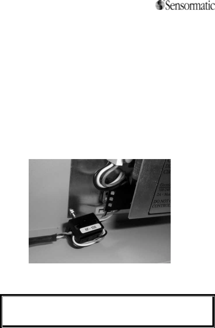
North America
To meet FCC (American) and Industry Canada requirements, the larger split bead must be placed
on the AC Power Cable of the Access Control Panel connected to the SCR-100 SmartCard
Reader to assure that the Radio-Frequency energy will not be coupled into the AC Power Line.
Install the bead inside the enclosure, near the power supply, as shown below. The jacket must be
removed to allow the wires to pass through the bead two times. The line, neutral, and safety
ground wires must be included in this turn. If several SCR-100 Readers are used, only one bead
is required.
Open the bead by gently prying the latch with a thumbnail or small screwdriver. Loop the wiring
as shown, then place the bead over the wires and gently squeeze shut until the latch snaps shut,
indicating that the cable has been correctly covered.
NOTE
Verify that the bead is snapped closed, as it does not provide the
required suppression otherwise.
ACCESS CONTROL DIVISION
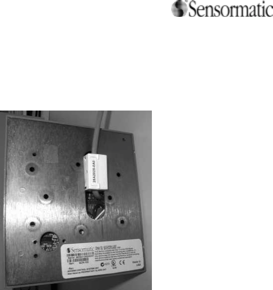
European Union
To assure that the installed SCR-100 SmartCard Reader does not exceed the ETSI limits for
radio-frequency emissions, please install the small high-frequency ferrite bead on the Reader
Data line near the Reader Unit as shown below.
Declarations
Regulatory Compliance: RM-Series Access Control and SCR-100 SmartCard Readers
EMC 47 CFR, Part 15
EN 300330
EN 300683
RSS 210
EN 50130-4
Safety Certified Class 2
EN60950 LPS
FCC COMPLIANCE: This equipment has been tested and found to comply with Part 15 of the FCC rules and the requirements
of Industry Canada RSS 210. Operation is subject to the following two conditions: 1) this device may not cause harmful
interference, and 2) this device must accept any interference received, including interference that may cause undesired operation.
CE NOTICE: This product is in compliance with the CE EMC and Electrical Safety Directives of the European Community
when used with the Sensormatic apC, apC/L or apC/8X product line.
EQUIPMENT MODIFICATION CAUTION: Equipment changes or modifications not expressly approved by Sensormatic
Electronics Corporation, the party responsible for FCC compliance, could void the user's authority to operate the equipment and
could create a hazardous condition.
Other Declarations
WARRANTY DISCLAIMER: Sensormatic Electronics Corporation makes no representation or warranty with respect to the
contents hereof and specifically disclaims any implied warranties of merchantability or fitness for any particular purpose. Further,
Sensormatic Electronics Corporation reserves the right to revise this publication and make changes from time to time in the
content hereof without obligation of Sensormatic Electronics Corporation to notify any person of such revision or changes.
LIMITED RIGHTS NOTICE: For units of the Department of Defense, all documentation and manuals were developed at private
expense and no part of it was developed using Government Funds. The restrictions governing the use and disclosure of technical

ACCESS CONTROL DIVISION
data marked with this legend are set forth in the definition of "limited rights" in paragraph (a) (15) of the clause of DFARS
252.227.7013. Unpublished - rights reserved under the Copyright Laws of the United States.