Tyco Safety Sensormatic AMB44 WIRELESS LR-WPAN IN 2.4 GHz BAND USING DIGITAL SS. User Manual ZBAMB2070 Handheld Mobile Deactivator 8200 0958 01
Tyco Safety Products/Sensormatic WIRELESS LR-WPAN IN 2.4 GHz BAND USING DIGITAL SS. ZBAMB2070 Handheld Mobile Deactivator 8200 0958 01
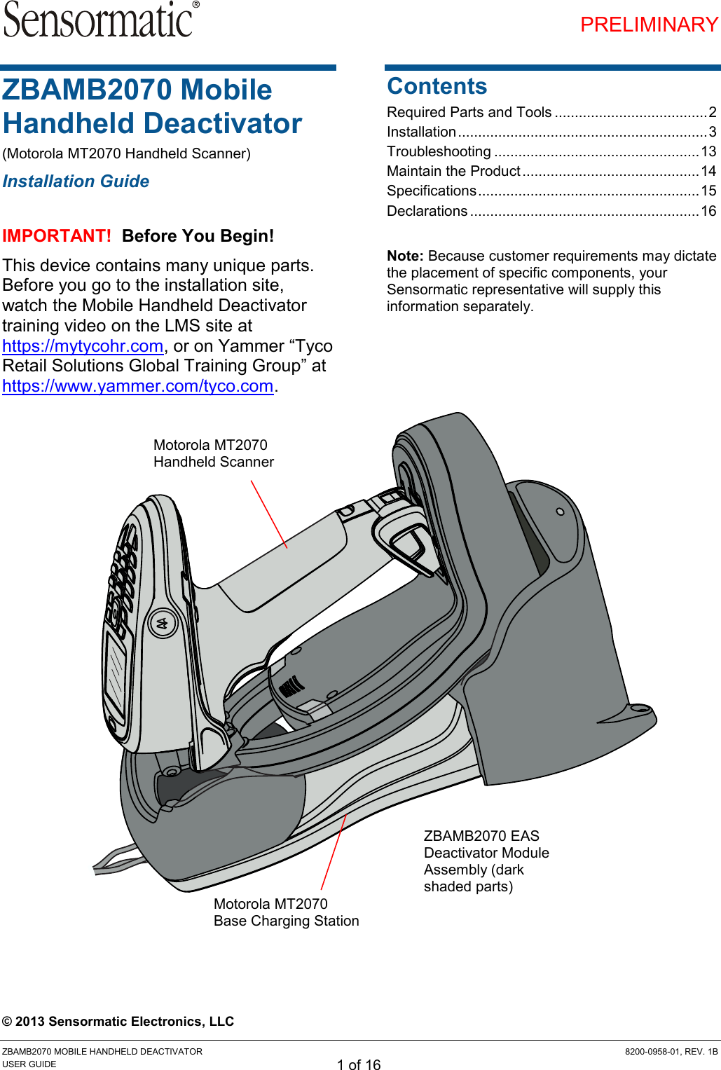
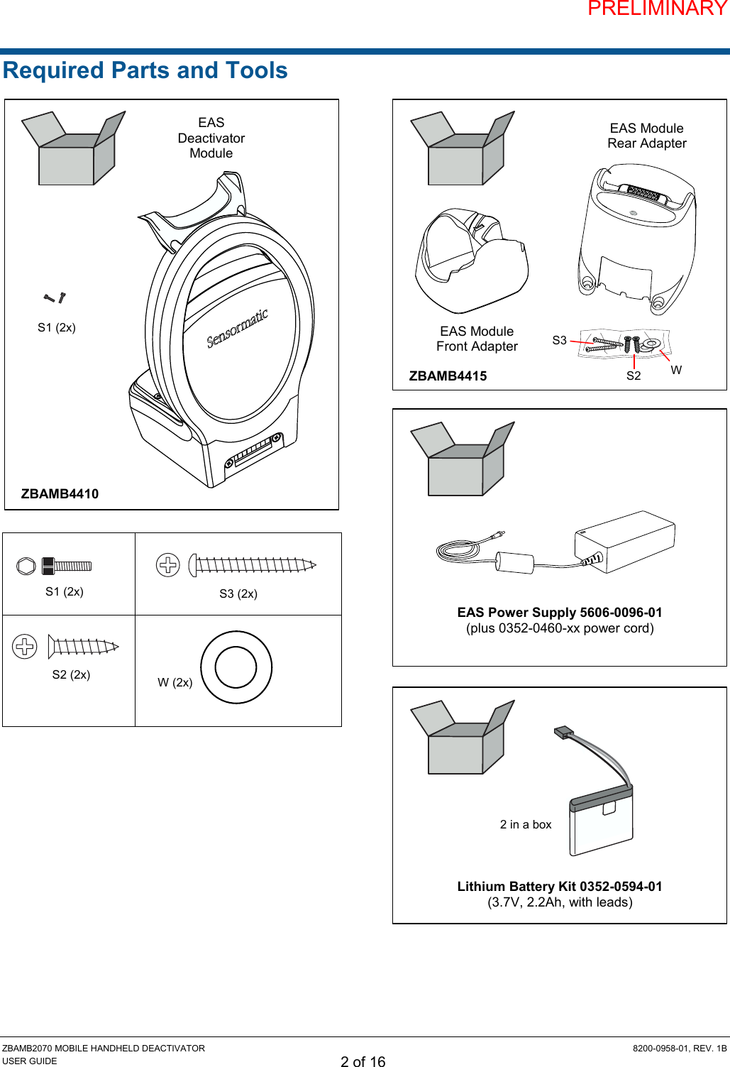
Contents
- 1. Install Guide
- 2. User Guide 1B
- 3. User Guide
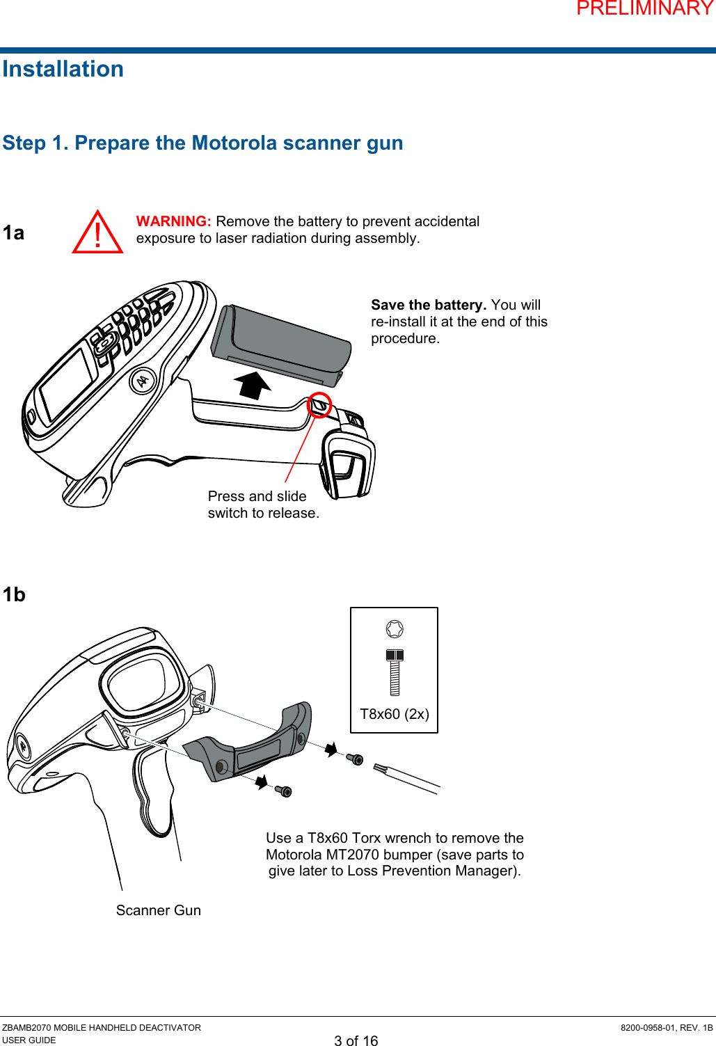
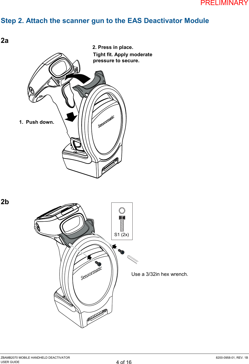
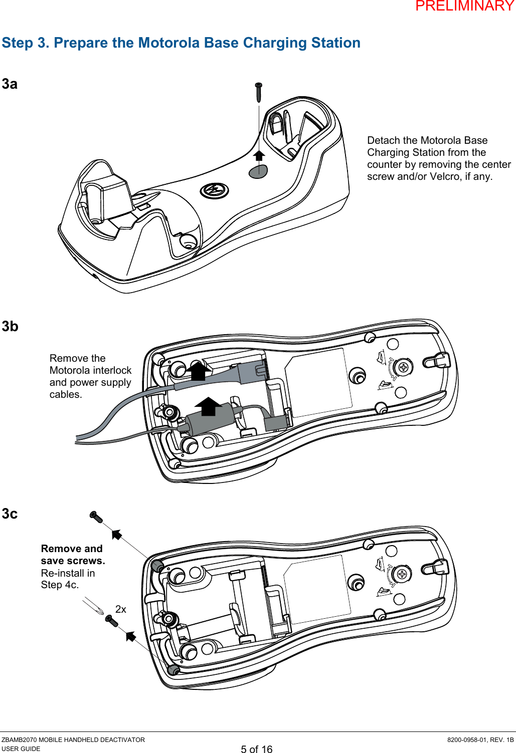
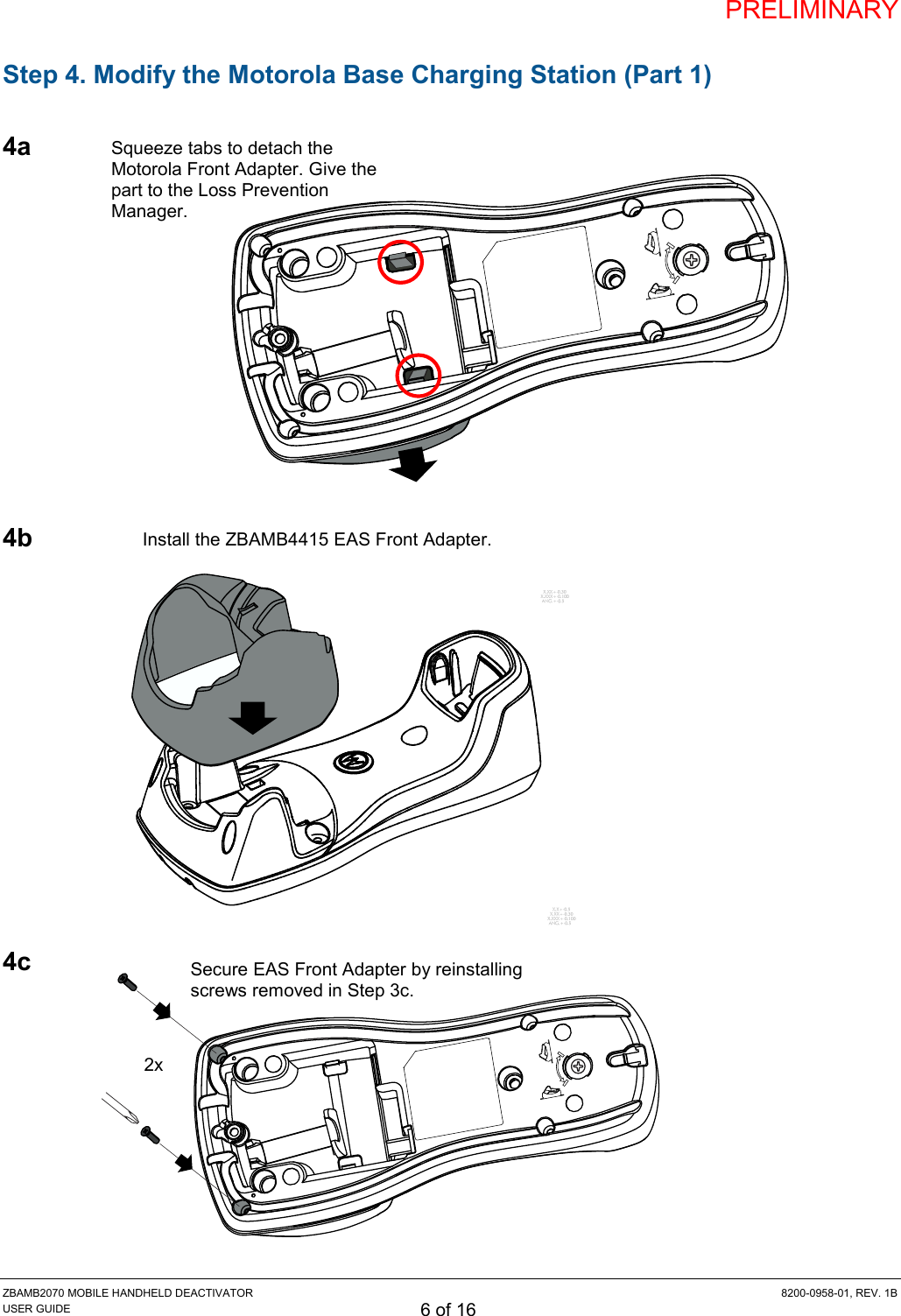
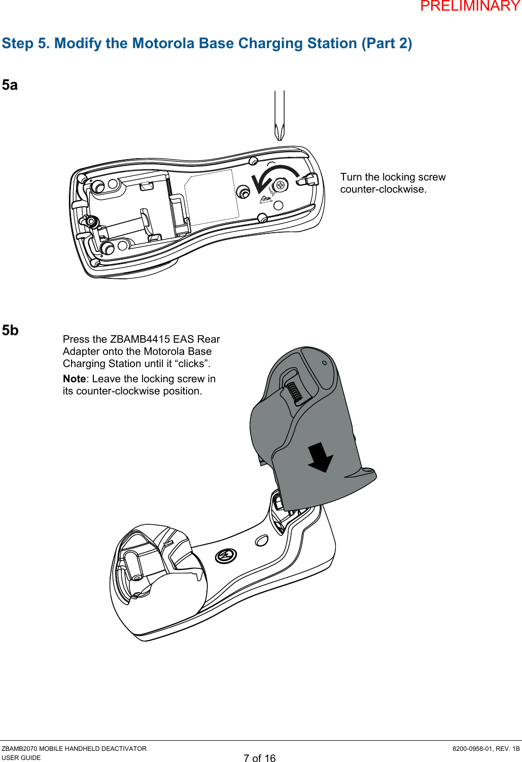
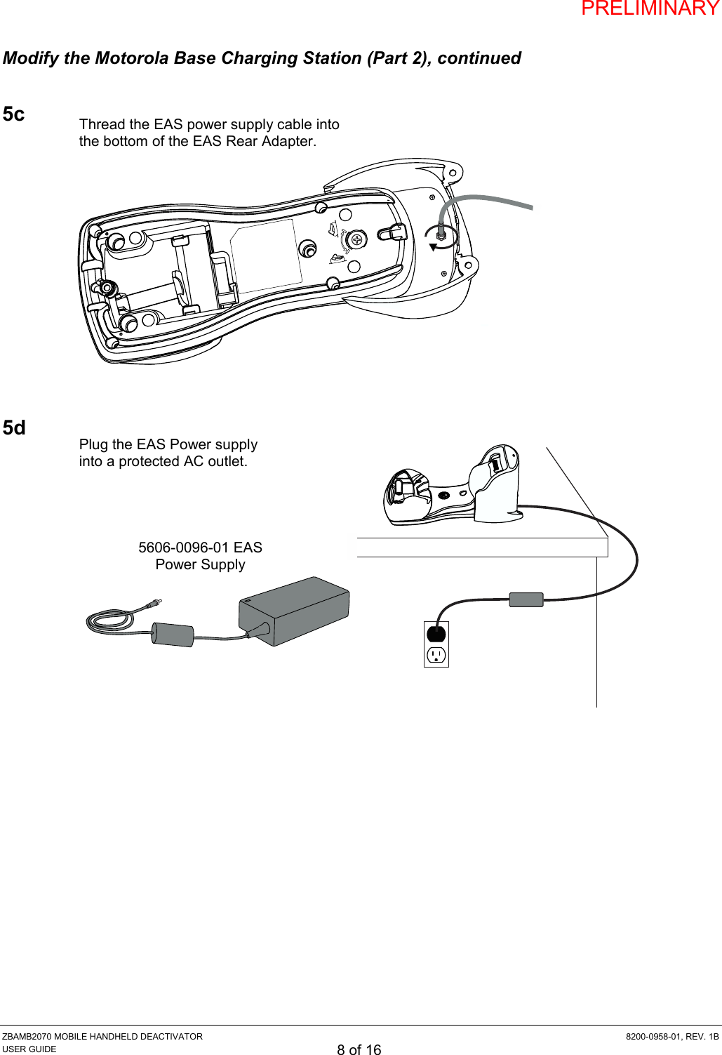
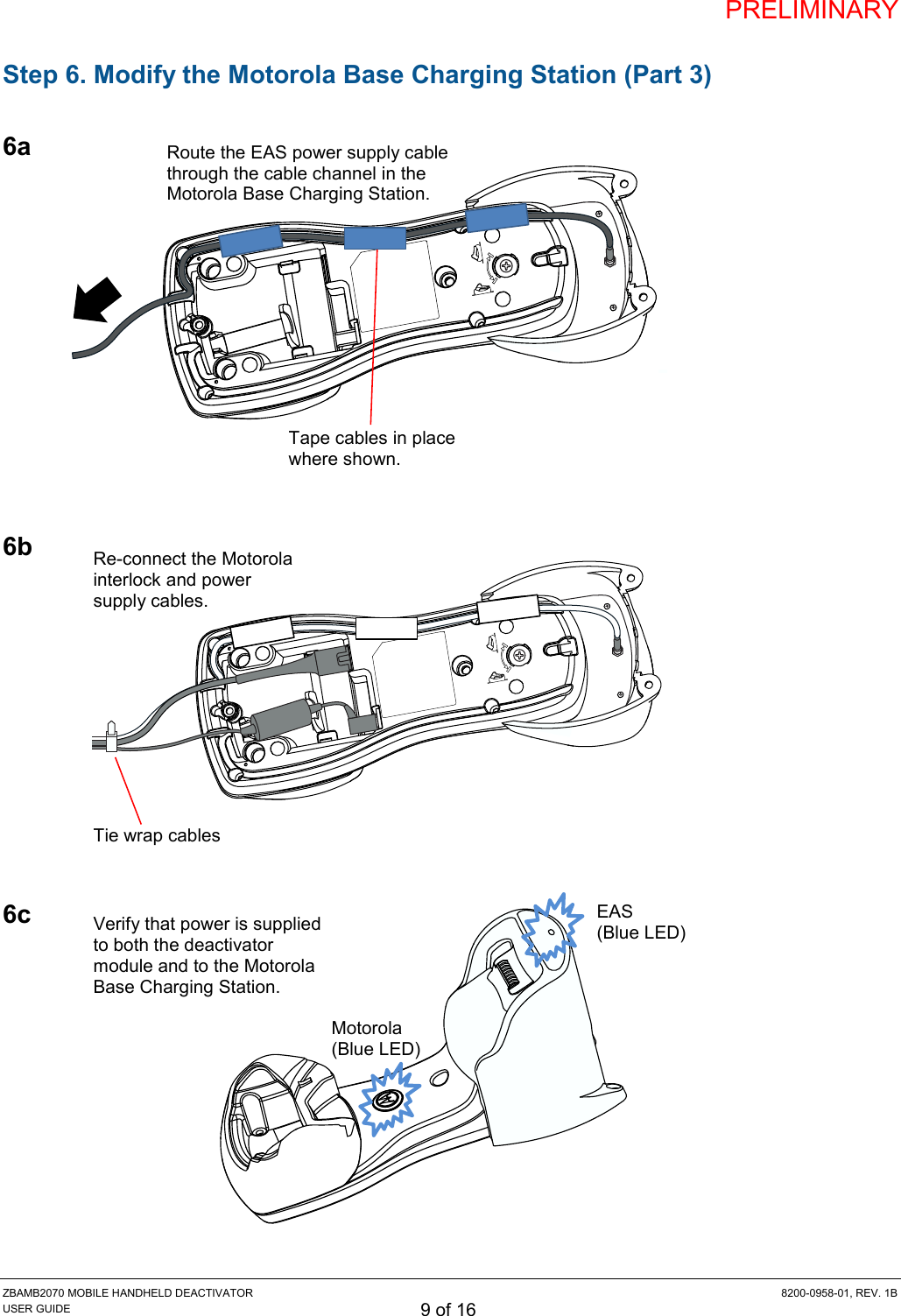
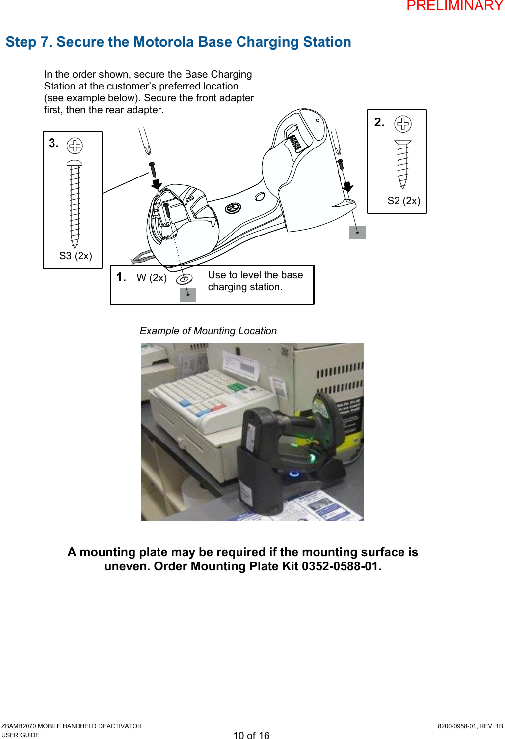
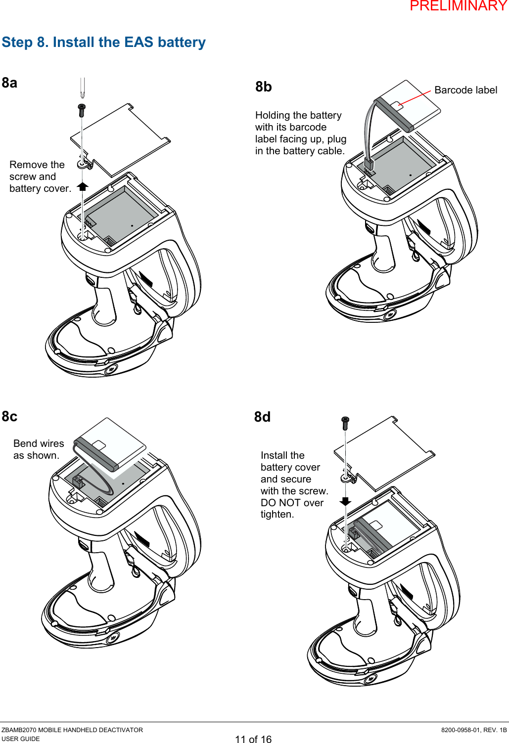
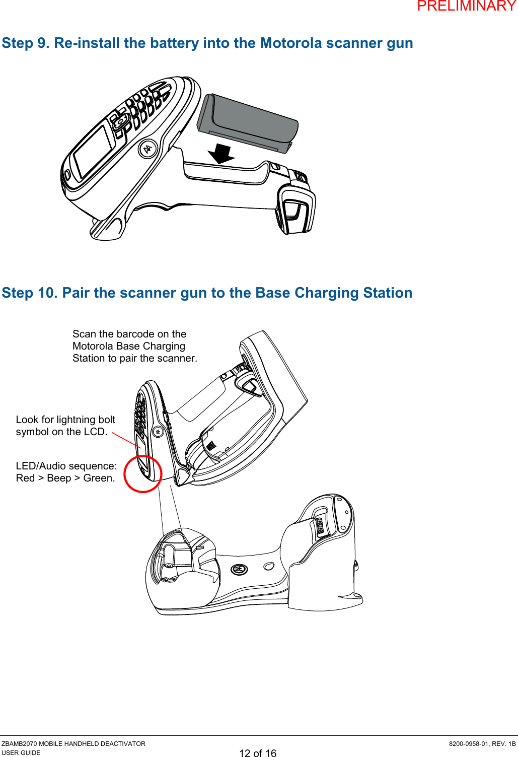
Install Guide