Tyco Safety Sensormatic AMB9010 ANTI-PILFERGAE DEVICE User Manual Install Guide
Tyco Safety Products/Sensormatic ANTI-PILFERGAE DEVICE Install Guide
Contents
- 1. INSTALL GUIDE
- 2. Install Guide
Install Guide
Preliminary
ZBAMB9010-IPS EAS LABEL DEACTIVATION CONTROLLER 8200-0747-24 REV. 3A
INSTALLATION GUIDE 1 OF 7
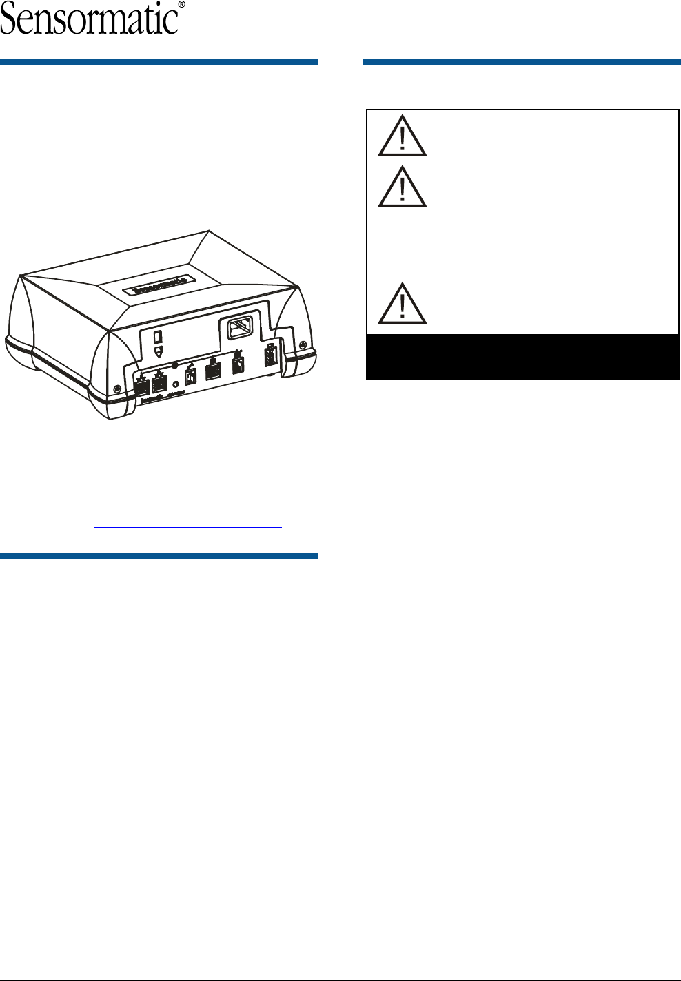
ZBAMB9010-IPS EAS
Label Deactivation
Controller
Installation Guide
TYPE: AMB-9010-IPS
If you need assistance…
For product bulletins, the most recent updates to
this document, or to contact a technical support
specialist, visit www.sensormatic.com/support.
About this Guide
This guide only covers hardware installation. For
setup information, see the setup guide for the
deactivation pad or coil being connected.
About the Product
European Regulatory Restriction:
None.
Declaration of Conformity: If this
product was installed in a European
Union or European Free Trade
Association member state, give the
Declaration of Conformity included with
this product to the manager or user. By
law, this information must be provided to
the user.
Intended Use: Only install this device
as described in this guide.
See page 4 for additional
WARNINGS and CAUTIONS.
Product Description
The ZBAMB9010-IPS deactivation controller
connects to a Sensormatic® low inductance
deactivation pad or coil to deactivate Ultra•Strip®
low energy security labels.
A Status LED on the deactivator is solid green
when power is applied.
Installation Options
On the countertop as described in this guide.
ZBSMP-B1 Under-Counter Mounting Bracket.
See installation guide 8200-0054-03.
ZPSTP-RA Remote Alarm Module See
installation guide 8200-0838-01.
Mechanical Specifications
Dimensions (L x W x H) ............... 26.2cm (10.3in) x
22.1cm (8.7in) x
10.1cm (4in)
Weight .......................................... 2.5kg (5.5 lbs)
Power cable length ....................... 18.3m (6ft)
© 2011 Sensormatic Electronics, LLC
Preliminary
ZBAMB9010-IPS EAS LABEL DEACTIVATION CONTROLLER 8200-0747-24 REV. 3A
INSTALLATION GUIDE 2 OF 7
Deactivation pads and coils used with
the controller:
Deactivation
Pad
Consists of one or two coils
inside a horizontal housing
Deactivation
Coil
A vertical or horizontal coil in
a standalone housing or
inside a barcode scanner
Note: This controller has been approved for use
with high inductance ScanMax Pro deactivation
pads, although not presently offered.
High Inductance Pads (ScanMax Pro)
Pad
Tx Power
ZBSMPLP (LP Pro)
Med
ZBSMPPP (PowerPad Pro)
Med
ZBSMPSP (SlimPad Pro)
Med
ZBSMPIP (IP Pro)
Med
ZBSMPCP (CompactPad Pro)
Med
Scanner Integrated High Inductance Coils
Coil
Tx Power
ZBSMPIS (ScanMax IS)
Med
ZBSMPNS2 (ScanMax NS2)
Med
ZBSMPHS (ScanMax HS)
Med
ZBAMB5110H, ZBAMB5110V
Med
ZBAMB5220A
High
ZBAMB5278A
Med
Low Inductance Pads / Coils
Coil / Pad
Tx Power
ZBAMB5010A Coil
Low
ZBAMB5011A Pad
Low
ZBAMB5012A Pad
Low
ZBAMB5182A Coils*
Low
ZBAMB5184A Coil*
Low
ZBAMB5185A Coil*
Low
ZBAMB5190A Coil*
Low
ZBAMB5274H, ZBAMB5274V Coils*
Low
ZBAMB5300A Coil*
Low
ZBAMB5780 Coil
Low
* Scanner integrated.
Internal features:
Automatic deactivation coil detection
Auto and re-synchronization
Adjustments to transmit and deactivation fields
Status LED for power on, communication
activity, and basic diagnostics.
EAS Label type (SR/DR).
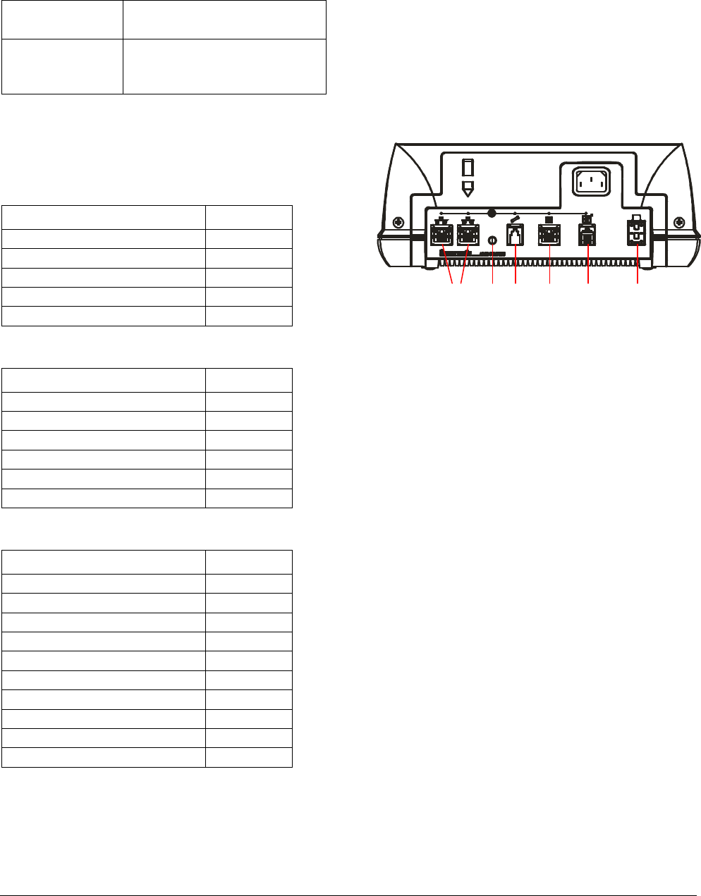
Front panel features:
a. Tie wrap slot. A tie wrap helps keep the power
cord from being accidentally disconnected from
the controller.
b. Power: AC power cord connects here.
c. RS-485 (Network) ports: Two 8-position
modular jacks provide RS-485 communication
between Sensormatic devices and a POS
system.
d. Status LED: Indicates deactivation status.
Status indications are mentioned in the setup
guides for the controller, pads, and coils.
e. Service port: This 4-position modular jack
provides RS-232 communication to a laptop
computer for advanced setup and diagnostics.
f. Scanner port: This 8-position modular jack
allows a POS system, such as a barcode
scanner, to control deactivation and also
provides RS-232 communication if required.
These ports accept various control voltages
(see specs on page 6).
g. Remote port: This 6-position RJ-11 modular
jack supports the ZPSTP-RA Remote Alarm
Module. Deactivation can be disabled on this
port.
h. Pad or coil cable port: The EEPROM cable
from the deactivation pad or coil plugs into this
port. The preprogrammed EEPROM enables
the controller to automatically identify the pad or
coil and adjust its parameters accordingly. If the
EEPROM is not programmed, controller settings
default to the PowerPad Pro deactivation pad.
a
b
c
e
f
g
h
d

Preliminary
ZBAMB9010-IPS EAS LABEL DEACTIVATION CONTROLLER 8200-0747-24 REV. 3A
INSTALLATION GUIDE 3 OF 7
Setup
A Deactivation Universal Configurator is used to
setup the controller. This configurator:
Installs on a laptop computer that plugs into the
SERVICE port.
Requires Microsoft® Windows® XP operating
software on the laptop.
Auto Detection
Auto detection enables the controller to adjust to
the deactivation pad or coil in use.
Synchronization
Auto synchronization. Upon power up, the
controller automatically syncs its transmission to
other nearby EAS systems, after which auto sync
is disabled.
Resynchronization. Enabled using the software
configurator, resynchronization enables the user to
manually force the controller to resync its
transmission to other nearby EAS systems.
Wired synchronization. The Universal Sync
standard (wired sync) is supported on the
NETWORK port as either transmit or receive
mode, and is set up in the software configurator.
POS Integration
A dedicated scanner port enables POS integration.
POS devices such as barcode scanners can
control deactivation when connected to the
scanner port.
POS devices must be programmed with special
software.
Voltage specifications are on page 6.
Networking
A network port provides the ability to enable an
external Sensormatic device such as an LDM II to
send data to a store’s POS network using the RS-
485 port for the purpose of remote diagnostics or
data mining. The external device must be
programmed with special software.
Preliminary
ZBAMB9010-IPS EAS LABEL DEACTIVATION CONTROLLER 8200-0747-24 REV. 3A
INSTALLATION GUIDE 4 OF 7
PRECAUTIONS
Please read the following precautions for:
Safety
Cleaning
Device interaction
Installation.
SAFETY
WARNING!
Hazardous areas.
DO NOT install this product in areas
where highly combustible or explosive
products are stored or used.
Power considerations.
Plug this product into an unswitched
AC outlet with less than 0.5Vac
between neutral and ground. This
product is designed to be operated on
a power system that includes a
protective earth terminal.
DO NOT connect to UPS power.
DO NOT plug or unplug any cable
with power on.
When the cordset is not provided with
this product, a cordset certified to the
national requirements of the country
of installation must be used.
Altitude limitation.
This product is evaluated for use at
altitudes up to 3200m (10,500ft).
WARNING—
RISK OF ELECTRIC SHOCK!
No user-serviceable parts.
DO NOT attempt to open this product.
Power cord / cable routing.
Route the power cord and deactivation
cables away from mechanisms whose
operation may pinch or otherwise
damage it. Failure to do so may damage
equipment or injure people nearby.
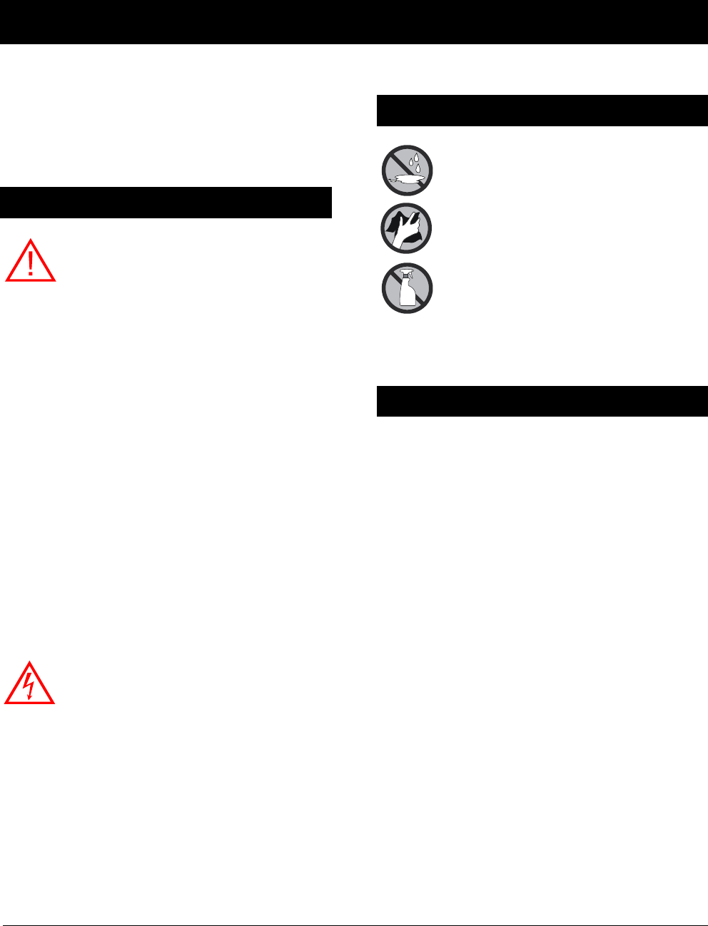
Cleaning
Wipe the housing with a soft cloth
moistened (not soaked) with mild
detergent. Then wipe off excess.
Keep spills from entering the housing.
DO NOT USE:
Spray cleaners.
Ammonia- or chlorine-based
cleaning solutions; they may
damage the housing or corrode
internal parts.
Abrasives, solvents, or flammable
liquids.
Installation
Ventilation. Install the controller in a location that
has adequate free space around it and is not likely
to be cluttered with debris.
Sidewall mounting. When the controller is
mounted to a sidewall of a counter, its cable
connectors MUST NOT face down.
Cable reach. Make sure the pad or coil cable can
reach the controller. Make sure the power cord and
power supply cable once plugged into the
controller can reach the AC outlet.
Preliminary
ZBAMB9010-IPS EAS LABEL DEACTIVATION CONTROLLER 8200-0747-24 REV. 3A
INSTALLATION GUIDE 5 OF 7
Installation
The controller can be placed on the countertop, or
using an optional ZBSMP-B1 mounting bracket
attached to the underside of the countertop or
sidewall of the counter.
WARNING! When the controller is
mounted to a sidewall of a counter, its
cable connectors MUST NOT face down.
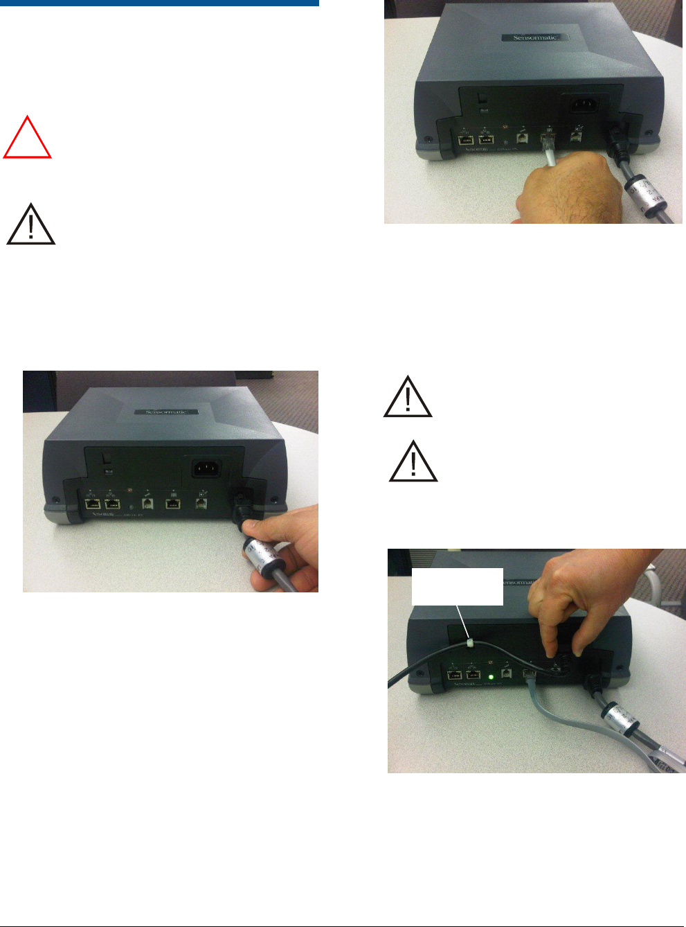
Procedure
CAUTION: To avoid damaging the
controller:
Perform the next three steps in order.
DO NOT reverse the steps.
DO NOT plug or unplug any cable with
power on.
1. Connect the deactivation pad or coil EEPROM
cable to the cable port of the controller.
2. Plug the barcode scanner interface cable (if
used) into the scanner port of the controller.
Plug the ZPSTP-RA Remote Alarm Module
cable (if used) into the remote port of the
controller.
3. Plug the AC power cord into the power supply
and its other end into an unswitched AC outlet
having less than 0.5Vac between neutral and
ground. The Status LED should be solid green.
Note: While the controller auto-synchronizes,
the Status LED may briefly flash amber. Auto-
sync can take up to ten seconds.
If the Status LED is solid red—
STOP— return the controller to an
authorized repair center.
Leave the coil EEPROM cable in
place if removing the controller for
service. The EEPROM maintains
system settings for the coil location
and will automatically update the new
controller.
4. Refer to setup instructions for the deactivation
coil.
!
Secure using
a cable tie.

Preliminary
ZBAMB9010-IPS EAS LABEL DEACTIVATION CONTROLLER 8200-0747-24 REV. 3A
INSTALLATION GUIDE 6 OF 7
Specifications
Electrical
Voltage input
to power supply............................ 100–240Vac,
50/60Hz (±5%)
Voltage input
from power supply ....................... 22.5Vdc
AC line current ............................. 2.5Arms max.
Scan I/O port:
Maximum input voltage ............ +25Vdc (±5%)
Input 1+ and Input 2+:
Input voltage ......................... ±5–12Vdc typical,
greater than 12V
observing the 32mA
maximum
Input current ......................... 10mA source minimum
Minimum pulse duration ....... 100ms
Detect out ............................. Open-collector side of
an opto-isolator
Maximum pull-up voltage ..... +25Vdc
This output remains in
the open state until
label detection occurs.
It then shorts to the
Detect Common for a
minimum of 39ms
based on label vicinity
to the antenna plus 7
detection windows
(5.555 x 7 = 39mS).
Detect common .................... Emitter side of the
Detect Out opto-
isolator. It normally
should be tied to D
Ground (J8, Pin 6).
Maximum current limit:
6.3mA @ Vce < 10V
2mA @ Vce < 0.4V
Environmental
Operating temperature ................. 0 to 40°C
(32° to 104°F)
Non-operating temperature .......... –40° to 70°C
(–40° to 158°F)
Relative humidity ......................... 0 to 90%
non-condensing
Mechanical
Height .......................................... 10.1cm (4in)
Width ........................................... 26.2cm (10.3in)
Depth ........................................... 22.1cm (8.7in)
Weight ......................................... 2.5kg (5.5 lbs)
Connector Inputs/Outputs
Each Network RS485 Port (8 pin modular jack)
Pin 1: RS485 HI (RS-485 Driver A)
Pin 2: RS485 LO (RS-485 Driver B)
Pin 3: Universal Sync A (RS-485 Driver A)
Pin 4: +5V* (Configurator controlled on/off, 250mA max.)
Pin 5: Spare +5V* (Configurator controlled on/off, 250mA
max.)
Pin 6: Universal Sync B (RS-485 Driver B)
Pin 7: D Ground
Pin 8: D Ground
*Can be +12V if powered by an LDM II.
Scanner Port (8-pin modular jack)
See specs opposite.
Pin 1: +5Vdc (125mA max.)
Pin 2: Scan In + (390 ohms in series with opto LED
anode)
Pin 3: Scan In – (opto LED cathode)
Pin 4: Detect Open Emitter (usually tied to D Ground, pin
6)
Pin 5: Detect Open Collector (0.15-0.4V @ 2mA output
low level when Detect OE grounded)
Pin 6: D Ground
Pin 7: RXD POS (RS-232 levels)
Pin 8: TXD POS (RS-232 levels)
Service RS-232 Port (4-pin modular jack)
Note: The Service Port should not be used for POS
applications. Use the Scanner Port.
Pin 1: RXD
Pin 2: TXD
Pin 3: D Ground
Pin 4: Not Connected
Remote Port (6-pin Modular Jack)
Pin 1: +22V (75mA max.)
Pin 2: Red LED
Pin 3: Green LED
Pin 4: Audio
Pin 5: Key Switch
Pin 6: P Ground
Antenna Out Ports
Pin 1: X
Pin 2: Y
Pin 3: X Ret
Pin 4: Y Ret
Pin 5: Chassis Ground
Pin 6: EEPROM Signal
Preliminary
ZBAMB9010-IPS EAS LABEL DEACTIVATION CONTROLLER 8200-0747-24 REV. 3A
INSTALLATION GUIDE 7 OF 7
Declarations
Regulatory Compliance
Pad/Coil
Regulatory ID
ZBSMPLP
DEAC STP-LP
ZBSMPPP
DEAC STP-PD
ZBSMPCP, ZBSMPCP-F
DEAC STP-CD
ZBSMPSP
DEAC STP-SD
ZBSMPIP
DEAC STP-SD
ZBSMPIS
DEAC STP-JD
ZBSMPNS2
DEAC STP-JD
ZBAMB5010A
AMB-5010
ZBAMB5010A2
AMB-5010
ZBAMB5011A
AMB-5011
ZBAMB5012A
AMB-5012
ZBAMB5110H, ZBAMB5110V
AMB-5110
ZBAMB5182A
AMB-5182
ZBAMB5184A
AMB-5184
ZBAMB5185A
AMB-5185
ZBAMB5190A
AMB-5190
ZBAMB5220A
AMB-5220
ZBAMB5274H, ZBAMB5274V
AMB-5274
ZBAMB5278A
AMB-5278
ZBAMB5300A
AMB-5300
ZBAMB5780
AMB-5780
EMC ........................................................ 47 CFR, Part 15
EN 55022
EN 55024
ICES-003
Safety (2nd Edit.) ............................................ UL 60950-1
CSA C22.2.60950-1
EN 60950-1
EMC ........................................................ 47 CFR, Part 15
RSS 210
EN 300 330
EN 301 489
Safety ............................................................ UL 60950-1
CSA-C22.2.60950-1
EN 60950-1
Environmental rating: ................................................ IP20
FCC COMPLIANCE: This equipment complies with Part 15 of
the FCC rules for intentional radiators and Class A digital
devices when installed and used in accordance with the
instruction manual. Following these rules provides reasonable
protection against harmful interference from equipment
operated in a commercial area. This equipment should not be
installed in a residential area as it can radiate radio frequency
energy that could interfere with radio communications, a
situation the user would have to fix at their own expense.
FCC COMPLIANCE: This equipment complies with the limits
for a Class B digital device, pursuant to Part 15 of the FCC
rules. These limits provide reasonable protection against
harmful interference in a commercial or residential installation.
This equipment can radiate radio frequency energy and, if not
installed and used in accordance with the instructions, may
cause harmful interference. If this equipment does cause
harmful interference to radio or television reception, which can
be determined by turning the equipment off and on, the user is
encouraged to correct the interference by one or more of the
following: reorient or relocate the receiving antenna, increase
the separation between the equipment and receiver, connect
the equipment on a circuit different from that to which the
receiver is connected, consult the dealer or an experienced
radio/TV technician for help.
EQUIPMENT MODIFICATION CAUTION: Equipment changes
or modifications not expressly approved by Sensormatic
Electronics, LLC, the party responsible for FCC compliance,
could void the user's authority to operate the equipment and
could create a hazardous condition.
Other Declarations
WARRANTY DISCLAIMER: Sensormatic Electronics, LLC
makes no representation or warranty with respect to the
contents hereof and specifically disclaims any implied
warranties of merchantability or fitness for any particular
purpose. Further, Sensormatic Electronics, LLC reserves the
right to revise this publication and make changes from time to
time in the content hereof without obligation of Sensormatic
Electronics, LLC to notify any person of such revision or
changes.
LIMITED RIGHTS NOTICE: For units of the Department of
Defense, all documentation and manuals were developed at
private expense and no part of it was developed using
Government Funds. The restrictions governing the use and
disclosure of technical data marked with this legend are set
forth in the definition of ―limited rights‖ in paragraph (a) (15) of
the clause of DFARS 252.227.7013. Unpublished - rights
reserved under the Copyright Laws of the United States.
TRADEMARK NOTICE: ScanMax and Sensormatic are
registered trademarks of Sensormatic Electronics, LLC. Other
product names mentioned herein may be trademarks or
registered trademarks of Sensormatic or other companies.
No part of this guide may be reproduced in any form without
written permission from Sensormatic Electronics, LLC.