Tyco Safety Sensormatic AMB9010 ANTI-PILFERAGE DEVICE User Manual INSTALL GUIDE
Tyco Safety Products/Sensormatic ANTI-PILFERAGE DEVICE INSTALL GUIDE
Contents
- 1. INSTALL GUIDE
- 2. Install Guide
INSTALL GUIDE
ZBAMB9010 BI-PLANAR ANTENNA CONTROLLER 8200-0747-01, REV. 4A
INSTALLATION AND SERVICE GUIDE 1 of 14
1ZBAMB9010 Bi-Planar
Antenna Controller
Installation and Service Guide
Contents
About this Guide.................................................... 1
About the Product.................................................. 2
Product Limitations................................................ 4
Device Interaction ........................................... 4
Deactivator Performance ................................ 4
Antennas......................................................... 4
Installation ............................................................. 4
Hardware Setup.............................................. 4
Software Setup ............................................... 5
Service Configurator Control Definitions ............... 7
Troubleshooting................................................... 11
Basic Troubleshooting .................................. 11
Advanced Troubleshooting ........................... 12
Specifications ...................................................... 13
Connector Inputs/Outputs ................................... 13
Declarations ........................................................ 14
© 2007 Sensormatic Electronics
About this Guide
This guide explains how to install, setup, and
troubleshoot the AMB-9010 controller. It does not
explain how to mount the controller and its
associated antenna into a counter or scanner.
Mounting instructions are supplied with the
mounting bracket and antenna.
Note: Because customer requirements dictate the
location of components at the customer site, your
ADT representative will supply this information
separately.
If you need assistance…
Customers: 1-800-241-6678
(Sensormatic/ADT Customer Response Center)
ADT Technicians (North America):
Sensormatic Technical Support
1-800-543-9740
Direct: 561-939-3290
Hours: 8 a.m. to 6 p.m. EST
Email: easts@sensortmatic.com
ADT Technicians (Europe): TFS EMEA
+800 CALLTYCO (+800.22.55.89.26)
UK only: +44 (0) 8701.238.787
France only: +33 (0) 4.72.79.14.83
Spain only: +900.10.19.45
Direct: +31 475.352.722
Fax: +31 475.352.725
Hours: 8 a.m. to 6 p.m. CET
Email: TFSEMEA.Support @ tycoint.com
www.tycosafetyproducts-europe.com
For all training inquires:
Email: TFSEMEA.Training@tycoint.com
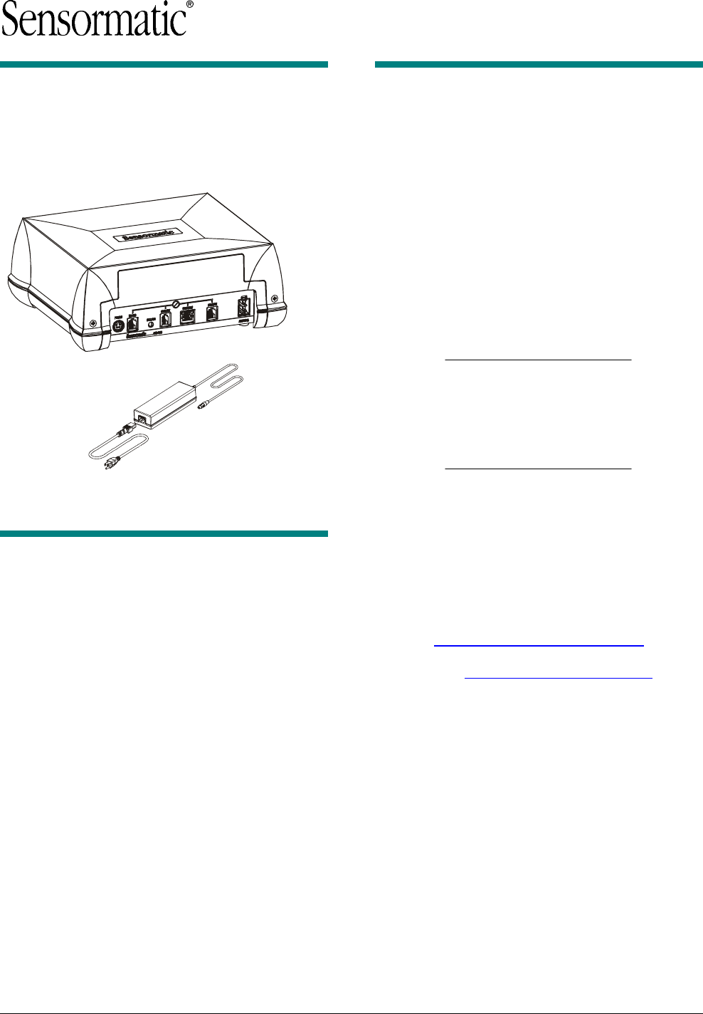
External
Power Supply
Controller
ZBAMB9010 BI-PLANAR ANTENNA CONTROLLER 8200-0747-01, REV. 4A
INSTALLATION AND SERVICE GUIDE 2 of 14
About the Product
The AMB-9010 controller connects to an AMB-
5182 low inductance antenna to detect and
deactivate security labels.
Antennas used with the controller:
Note: An EEPROM in the antenna cable
automatically adjusts the controller to the antenna’s
characteristics. If the EEPROM is not programmed,
the antenna type settings default to PowerPad Pro.
Low Inductance Antennas
Deactivation Height
Antenna*
Tx
Power
Full
Power
MMS
Power
AMB-5182
(ZBAMB5182)
Normal 20–22.5cm
(8–9in)
N/A
Internal features:
• External power supply with a universal ac input and
22Vdc output and line sync signal to the controller.
• Automatic antenna type detection, except if using an
optional antenna cable extension.
• Auto and re-synchronization
• Adjustments to transmit and deactivation fields to
correct for counter thickness
• Remote key switch detection
• Status LED for power on, communication activity, and
basic diagnostics.
• Label type (SR/DR) and power level (full or MMS).
• Advanced settings.
• Diagnostics.
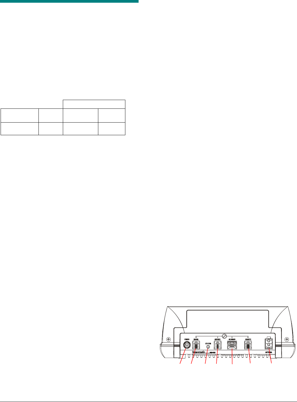
Front panel features:
a. Power: External ac-dc power supply connects here.
b. RS-485 (Network) port: This 6-position modular jack
provides RS-485 communication between
Sensormatic devices and a POS system. An RS-485
based Remote provides AcoustoLink and FootLink
functionality on this port.
c. Status LED: For indication of power on/antenna
connected (green), antenna disconnected (off),
deactivation disabled (green blinking), deactivation
(orange blinking), and non-recoverable fault (red).
d. SERVICE port: This 4-position modular jack provides
RS-232 communication to a laptop computer for
advanced setup and diagnostics.
e. SCANNER port: This 8-position modular jack allows
a POS system, such as a bar code scanner, to
control deactivation and also provides RS-232
communication if required. These ports accept
various control voltages (see specs on page 13).
f. REMOTE port: This 6-position RJ-11 modular jack
supports the legacy Sensormatic remote alarm
module. Deactivation can be disabled on this port.
g. ANTENNA port: Receives a cable from the antenna.
a b c d e f g
ZBAMB9010 BI-PLANAR ANTENNA CONTROLLER 8200-0747-01, REV. 4A
INSTALLATION AND SERVICE GUIDE 3 of 14
Power Cord
Power cord length is 183cm (6ft). The cord attach-
es the external power supply to an ac outlet. The
type of cord used depends on the country of use.
Setup
A software configurator is used to setup the
controller. The configurator:
• Installs on a laptop computer that plugs into the
SERVICE port.
• Requires Windows® 2000 or XP operating
system software on the laptop.
Auto Synchronization
Enabled using the software configurator, auto
synchronization:
• Upon power up, automatically synchronizes the
controller to the strongest signal picked up by
an antenna.
• Enables the controller to sync its transmission to
other nearby EAS systems to prevent their
interference during tag detection.
• The Universal Sync standard (wired sync) is
supported on the NETWORK port as either
transmit or receive mode, and is set up in the
software configurator.
• If Sensormatic devices using wireless sync are
nearby, an RS-485 based Smart Remote that
plugs into the NETWORK port on the controller
can be used to achieve synchronization.
POS Integration
POS devices such as bar code scanners can
control deactivation when connected to the
SCANNER port.
• POS devices must be programmed with special
software.
• Voltage specifications are on page 13.
Networking
A Sensormatic peripheral device such as an EAS
detection system can send data to a store’s POS
network using the RS-485 and SCANNER ports.
The peripheral device must be programmed with
special software.
LED Indications
Status LED. Note: Orange may appear yellow.
Green on Unit ready
Orange blinks once Deactivation attempted
Green blinking Deactivation disabled
Red on Non-recoverable fault
Off Antenna not connected
Remote Alarm Module (if used)
Green on, red off Unit ready.
Red blinks once Deactivation attempted
Green blinking Deactivation disabled in
detect only mode or by
key switch or config-
urator.
Green and red blinking
(For PowerPad Pro,
orange blinking)
Controller is in auto-sync.
Green on, red blinks
every 250ms
The high voltage circuit is
not working.
One beep The controller attempted
to deactivate a label.
Slow beep until a hard tag
is removed from the field.
The controller is in
Hard Tag Test mode.
Multiple fast beeps Label present in
Doublecheck or Detect
Mode.
Red on Label present in Detect
Mode.

ZBAMB9010 BI-PLANAR ANTENNA CONTROLLER 8200-0747-01, REV. 4A
INSTALLATION AND SERVICE GUIDE 4 of 14
Product Limitations
Device Interaction
Nearby Devices
Deactivation affecting nearby devices. The
antenna’s deactivation field can affect devices such
as credit card and check readers (alone or in
keyboards). As a rule, keep these devices at least
30.5cm (12in) from the antenna. If they cannot be
moved further away, contact Sensormatic technical
support for guidance.
Nearby devices affecting deactivation.
Computer monitors, TVs, switching power supplies,
laptops, and neon displays can affect deactivation.
Keep the antenna as far from these devices as
possible.
Checkout Counters
Ferrous metal around the antenna can distort the
antenna field and significantly reduce label
detection. Always test the performance of the
antenna before modifying the counter.
Between Deactivators
Keep antennas at least 15cm (6in) from each
other.
Nearby Security Tags
Do not place detached hard tags within 30.5cm
(12in) of the antenna.
Deactivator Performance
The controller can deactivate no more than twice a
second. Maximum throughput of labeled
merchandise is 200cm/sec (80in/sec) unless
otherwise limited by the antenna.
Antennas
Maximum distance between an AMB-5182 antenna
and the controller is 2m (6.6ft) when using the
cable extension.
Installation
The controller can be placed on the countertop, or
using a mounting bracket attached to the underside
of the countertop or sidewall of the counter.
WARNING! When the controller is
mounted to a sidewall of a counter, its
cable connectors must face down.
Hardware Setup
Equipment Required
• AMS-9010 controller
• AMB-5182 low inductance antenna
• Hard tag (non-deactivateable Ultra•Max® tag)
• Ultra•Max deactivateable low energy labels.
Also required for advanced setup:
• Laptop with Windows® 2000 or Windows XP
operating software
• Universal service configurator 1.0
• RS-232 Ultra•Max programming cable.
WARNING! Plug the output cable of the
external power supply into the controller
and its power cord into an unswitched ac
outlet having less than 0.5Vac between
neutral and ground. This system is
designed to be operated on a power
system that includes a protective earth
terminal.
WARNING! Do not plug or unplug ANY
controller cables with power on.
WARNING—
RISK OF ELECTRIC SHOCK!
Keep the power cord and antenna cable
away from cash drawers and other items
whose operation may pinch or otherwise
damage them. Failure to do so can
damage equipment or injure people
nearby.
WARNING! Ferrous metal in the counter
can affect antenna operation. ALWAYS
test the antenna before installing it.
!
!
!
!
ZBAMB9010 BI-PLANAR ANTENNA CONTROLLER 8200-0747-01, REV. 4A
INSTALLATION AND SERVICE GUIDE 5 of 14
Procedure
CAUTION: If using the antenna cable
extension, DO NOT USE THIS
PROCEDURE. Instead, perform the
advanced setup procedure on page 6.
1. Ensure the controller is powered off.
2. Plug the antenna cable into the ANTENNA port.
3. If used, plug the cable of the remote alarm
module into the REMOTE port.
4. If a bar code scanner is to enable deactivation,
plug its cable into the SCANNER port.
5. Plug the output cable of the external power
supply into the controller and its power cord into
an unswitched ac outlet having less than 0.5Vac
between neutral and ground.
Note: While the controller auto-synchronizes (if
enabled), The Status LED may briefly blink
green and red. Auto-sync can take up to ten
seconds.
Note: If the Status LED blinks continuously or is
solid red, the controller is not repairable.
Contact the ADT Customer Response Center
for service.
CAUTION: Never unplug the output
cable of the external power supply
from the controller if its power cord is
plugged into an ac outlet.
6. Using the software configurator, set the correct
label type (SR or DR).
Software Setup
The software configurator:
• Has the following four screens to setup and
diagnose the deactivator: Setup, Config
Antenna #1, Config Antenna #2 (not used), and
Network. The Engineering screen is not
accessible.
• Is downloaded onto a laptop computer that
plugs into the SERVICE port on the controller.
Equipment required for advanced setup:
• EAS non-deactivateable tag
• Laptop computer with Windows® 2000 or
Windows XP operating software
• Universal service configurator 1.0
• RS-232 Ultra•Max programming cable.
CAUTION: Do not place the laptop on the
antenna. Strong fields from the antenna
can damage the hard drive. Also, laptops
on or near the antenna can generate
58kHz noise in the label detection
circuitry.
Settings Available with the Configurator
Using the service configurator, antenna perfor-
mance can be manually adjusted and monitored
(except label type and deactivation power level).
The performance features listed below are fully
described beginning on page 7.
Transmit power
- Transmit power level
- Detection compensation.
Deactivation performance
- Monitoring of total hours of operation, number of
deactivations for each antenna, and summation
of deactivations for both antennas
- Thermal count (of deactivation)
- Line sync adjustments
- Auto sync disable and manual restart of auto
synchronization (re-sync)
- Doublecheck (mostly used with the optional
FootLink device)
- Detect only (deactivation disabled)
- Hard tag check.

ZBAMB9010 BI-PLANAR ANTENNA CONTROLLER 8200-0747-01, REV. 4A
INSTALLATION AND SERVICE GUIDE 6 of 14
System integration
- Remote key switch enable, if used
- Audio enable (for certain antennas and remote
alarm module)
- Output on detect
- Scan enable time adjustment.
Diagnostics (these settings turn off once you exit
the configurator)
- Transmit disable
- Deactivation disable
- Deactivation on the V or H antenna coil
- V and H coil noise meters.
Networking
- Baud rate selection for SyncLink, MaxCalibur, or
future Sensormatic peripheral
- Poll SyncLink (to interrogate a wireless synchro-
nization module when connected to controller).
- Poll MaxCalibur (not used).
Setup Using the Configurator
1. Follow the hardware setup on page 4.
2. Connect the Ultra•Max programming cable to
the laptop and to the SERVICE port.
3. On the desktop, click the icon to open the
service configurator.
4. On the Setup screen, verify the setting for label
type (SR or DR), deactivation power level (Full),
and transmit power (Normal).
Note: MMS is not available for the AMB-5182.
5. On the Config Antenna 1 screen:
- If using the antenna cable extension,
click EXTENSION USED.
- Verify Dx HEIGHT default setting for the
antenna used (see table on page 1).
- Adjust the following settings as required:
KEY SWITCH (enable, disable) and AUDIO
(enable, disable), if a remote alarm module is
used.
SCAN ENABLE TIME (1–30sec).
DETECTION COMPENSATION (V and H) to
compensate for things that can affect the
detect/deactivation field such as metal
countertops.
OUTPUT ON DETECT, DOUBLECHECK,
and DETECT ONLY.
- Check the noise level meters. See
troubleshooting if noise or detection height is
interfering with tag detection.
6. Click EXIT to exit the configurator.
7. If RS-232 communication is desired with a POS
device, plug its cable into the SCANNER port.
8. If a bar code scanner is to control deactivation,
plug its EAS cable into SCANNER port. Then
enable OUTPUT ON DETECT.
9. To verify operation, swipe a deactivateable label
across the antenna (a gentle thump is heard)
and then pass it through the label detector at
the exit (it should not alarm).
Performing Diagnostics
Using the service configurator, the following
settings can facilitate diagnostics (these settings
return to their default states once you exit the
configurator).
- Transmit disable
- Deactivation state disable
- Deactivation on V or H antenna coil
- V-coil and H-coil noise meters.
ZBAMB9010 BI-PLANAR ANTENNA CONTROLLER 8200-0747-01, REV. 4A
INSTALLATION AND SERVICE GUIDE 7 of 14
Service Configurator
Control Definitions
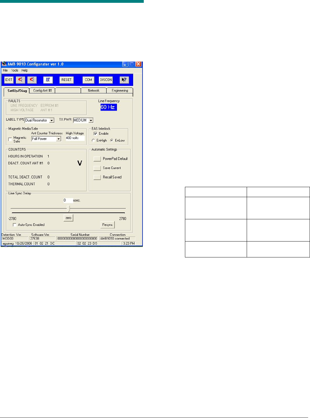
Setup Tab
Clicking the Setup tab brings up the Setup screen.
Settings on this screen are as follows:
Note: Default settings are in antenna EEPROM.
• Faults (indicated by red text).
- Line Frequency Fault: Frequency is outside
of 47–52Hz or 58–63Hz.
- High Voltage Fault: Voltage is unable to
reach the set point.
- EEPROM fault: The controller cannot read
from or write to the antenna EEPROM.
- ANT #1 fault: Ant. port not sensing antenna.
• Line Frequency. Displays the input frequency.
• Label Type. Default is dual resonator. Use the
pull down menu to select other label types.
• Tx Power (Low, Medium, High). Use “Normal”.
Use “Low” only for special applications.
• Magnetic Media Safe (MMS).
- Magnetic Safe (on, off). Use with MMS
capable antenna to set the controller for low
power deactivation to protect magnetic
media.
- Antenna/Counter Thickness/High Voltage.
Using the pull down menu, select the
counter thickness encountered and the
related high voltage set point.
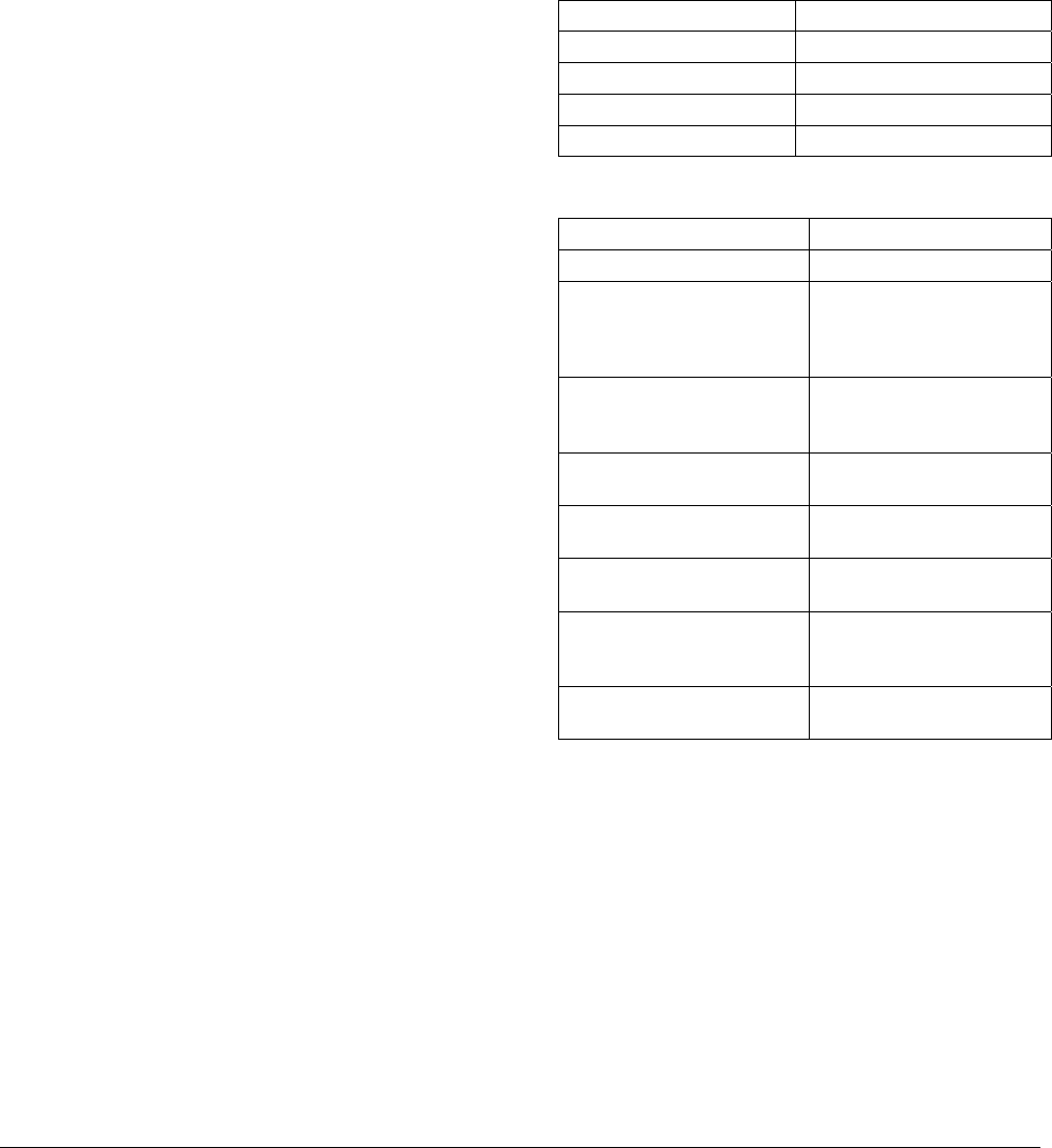
• Counters (for display only—not resettable).
- Hours of Operation: Total hours of
operation.
- Deactivation Count Ant.1: Total antenna
deactivations.
- Total Deactivation Count: Total counts for
Antenna 1 plus Antenna 2.
- Thermal count. The deactivation rate is
monitored to prevent heat build-up in the
controller. Six minutes of no deactivations
must occur for the count to drop below 120.
When the Count Is: The Unit Can Do:
Below 120. 3 deactivations every
second (maximum of
50 in 20 seconds).
Greater than 120 but
less than 400.
1 deactivation every
1.5 seconds for 2
minutes.
Greater than 400. 1 deactivation every 3
seconds indefinitely.
• Automatic Settings
• Line Sync Delay. Use the following when
transmit fields from other systems interfere with
tag/label detection:
- Auto Sync Enabled (on, off). Enable so
upon power up, the controller automatically
synchronizes to transmit fields of other EAS
systems so they do not interfere with tag
detection; otherwise, disable.
- Line Sync Delay (60Hz: –2780 to +2780
µsec, 50Hz: –3333 to +3333µsec). Use the
slider to manually adjust (in real time) tag
detection away from the interference
(overrides auto sync function). Use the zero
button to return exactly to the ac line phase.
- Resync. If high noise levels are still affecting
tag detection after auto sync completes, use
this button to resync the controller.
ZBAMB9010 BI-PLANAR ANTENNA CONTROLLER 8200-0747-01, REV. 4A
INSTALLATION AND SERVICE GUIDE 8 of 14
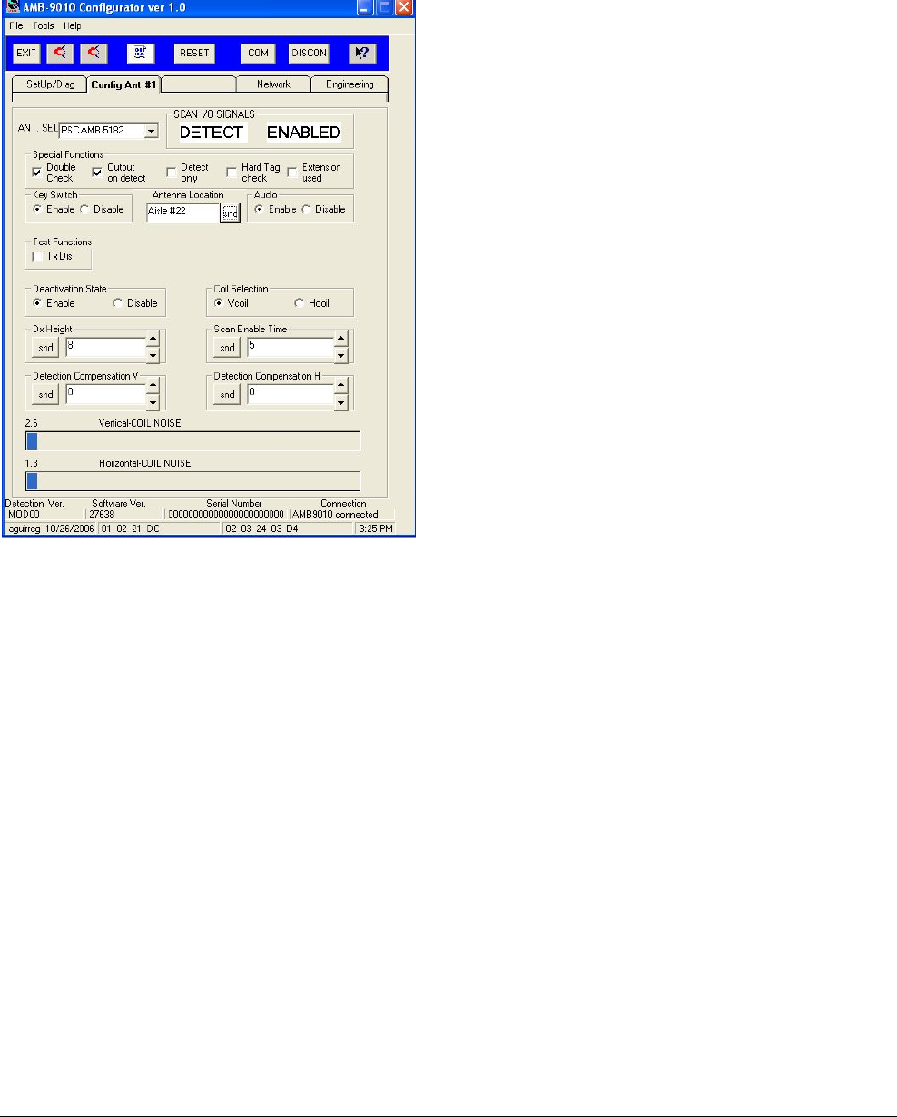
Config Antenna Tab
Clicking on the Config Ant #1 tab brings up the
Config Antenna screen.
Settings on this screen are as follows:
• Antenna Select. Select the antenna to be
operated from the Antenna port.
• Scan I/O Signals
• Special Functions.
- Doublecheck. Check to have the remote
alarm module emit a tone upon tag/label
detection. (This feature is mostly used with a
FootLink device. Disable Hard Tag Check
when using this feature.)
- Output On Detect. Check to enable the
detection output signal of the SCAN I/O port.
If checked, “Detect” and “Enabled” are
displayed on the screen.
- Detect Only. Check to have the controller
only detect labels (deactivation disabled).
- Hard Tag Check. Check to prevent
deactivation when a hard tag is in the
detection field. If using a remote alarm
module, one beep per second occurs from
the module until the tag is removed.
- Extension Used. Check when an antenna
cable extension is used.
• Key Switch (enable, disable). Enables or
disables detection by the controller of the
remote alarm module, when used.
• Audio (enable, disable). Enables or disables
audio in certain antennas or in the remote alarm
module, when used.
• Test Functions.
- Transmit Disable (on, off). Enables or
disables the transmitter.
- Deactivation State (enable, disable). Enables
or disables deactivation. Deactivation is
enabled once the configurator is exited.
- Coil Selection (V Coil, H Coil). This selection
enables manual deactivation on the vertical
or horizontal antenna coil using manual
deactivation buttons 1 or 2 at the top of the
screen.
• Dx Height (in inches). Adjusts deactivation
height depending on the type of antenna used
(overrides deactivation height set by the
antenna cable EEPROM). Click SEND (snd) to
actuate this setting.
• Scan Enable Time (1-30 sec.). Selects how
long the deactivator is enabled when controlled
by an external device such as an AcoustoLink.
Click SEND (snd) to actuate this setting.
• Detection Compensation (V, H coils). The
detection threshold can be adjusted to account
for special mounting, counter configurations, or
noise interference. Click SEND (snd) to actuate
this setting.
• X and Y Coil Noise Meters. Show in-band
noise levels picked up by X and Y antenna
coils.
ZBAMB9010 BI-PLANAR ANTENNA CONTROLLER 8200-0747-01, REV. 4A
INSTALLATION AND SERVICE GUIDE 9 of 14
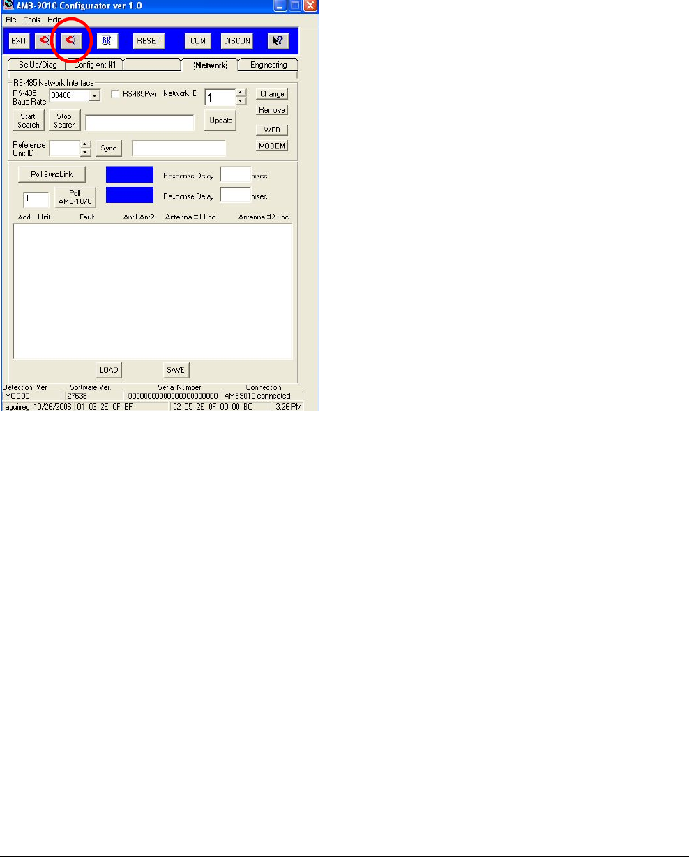
Network Tab
Clicking on the Network tab brings up the Network
screen.
Settings on this screen are as follows:
• RS-485 Network Interface
- RS-485 Baud Rate. Selects the baud rate for
the external device connected to the RS485
port on the controller: 19200 (SycnLink) or
38400 (MaxCalibur).
- RS-485 Power. When checked, provides
+5V power on the Network Port (J2, pin 6).
Default is unchecked (+5V off).
- Network ID. Selects
- Start/Stop Search.
- Update.
- Reference Unit ID.
- Sync.
- Change, Remove, Web, Modem
• Poll SyncLink (Wireless Sync) Button. Click
to interrogate a SyncLink wireless sync device,
if connected. The response is either “active” or
“inactive (blank)”. If active, the response delay
is shown.
• Poll AMS-1070 Button. Click to interrogate an
AMS-1070 label detector, if connected. The
response is either “active” or “inactive (blank)”.
If active, the response delay is shown.
• Screen below. xxx.

ZBAMB9010 BI-PLANAR ANTENNA CONTROLLER 8200-0747-01, REV. 4A
INSTALLATION AND SERVICE GUIDE 10 of 14
Engineering Tab
Not accessible! This tab is password protected for
engineering use only!
Pull-Down Menus (from left to right)
• File
Exit. Click to exit the program.
• Tools
Flash Download. Click to download new
firmware from the laptop to the controller.
• Help
Click to bring up on-line help and “About”
information. “About” displays the program
version, date, and copyright information.
Button Commands (from left to right)
Exit. Click to exit the service configurator and
return to the computer desktop.
Manual deactivation 1. Click to have the
deactivator fire one pulse through Antenna 1.
Works with Coil Selection on Config Ant #1 screen.
Manual deactivation 2. Click to have the
deactivator fire one pulse through Antenna 2.
Works with Coil Selection on Config Ant #2 screen.
Flash Download. Click to download new firmware
from the laptop to the controller.
Reset. Click to reset the microprocessor if the
controller functions improperly.
Com. Click to select the com port the laptop
computer will be using. This button is not required
for computers having one com port.
Disc. xxx.
Help. Click to bring up on-line help and “About”
information. “About” displays the program version,
date, and copyright information.
Bottom of Screens
• Detection Ver. Displays the detection version
currently used.
• Software Ver. Displays the software version
currently used.
• Serial Number. Not available.
• Connection. Indicates communication status
with the controller.

ZBAMB9010 BI-PLANAR ANTENNA CONTROLLER 8200-0747-01, REV. 4A
INSTALLATION AND SERVICE GUIDE 11 of 14
Troubleshooting
Troubleshooting consists of basic troubleshooting
where no tools are required, or advanced trouble-
shooting where a service configurator is required.
Always complete basic troubleshooting before
performing advanced troubleshooting.
Note: If the Status LED is solid red, the controller
is not repairable. Call the Customer Response
Center for service.
Note: If the controller is to be exchanged for a new
one, no set-up is required; the new controller will
adapt the settings of the old one. Simply plug in all
cables and turn the controller on.
Basic Troubleshooting
Use this procedure when:
- Deactivator is not deactivating labels
- Deactivation is continuous
- Deactivation height is low
No Deactivation Occurs
Possible causes: No power, remote alarm module
removed or damaged, or tag on the fringe of the
deactivation area.
1. Ensure all cables are plugged into the
controller. Do not hot plug the antenna cable or
the power cable from the external power supply.
2. Is the external power supply LED solid green?
• No. Check external supply connections. If
OK, check the store’s breaker panel.
• Yes. Continue.
3. Check the color of the Status LEDs.
• Solid green—go to next step.
• Blinking green—Deactivation is disabled.
This can occur if the key on the remote alarm
module was turned to OFF. To enable
deactivation and to bypass any scan-enable
function, turn the key switch to ON. If LED
still blinks, see “Advanced Troubleshooting”.
4. Check if a tag is on the fringe of the Dx area.
• If a remote alarm module is used: A slow
‘beep’ indicates a tag is present.
• If the remote alarm module is not used:
Cycle power by briefly unplugging the
external power supply power cord. If the
Status LED is solid green and 2 to 3
deactivations occur immediately and stop, a
non-deactivateable label is present.
If no tag/label is found, call the Customer
Response Center for service.
Deactivation is Continuous
Possible causes: Non-deactivateable tag/label
within the deactivation area, or the antenna picked
up interference from nearby POS equipment.
- Locate and remove the offending tag/label.
- Try repositioning devices that may cause
interference such as card readers and displays.
Typically, these devices should be 30.5cm
(12in) from the antenna.
Tip: If these devices cannot be repositioned and
the antenna is placed on the countertop, try this:
Remove the antenna and rotate it horizontally
and vertically until deactivation stops. If the
antenna’s new position is acceptable,
troubleshooting is complete.
If deactivation continues, see “Advanced
Troubleshooting”.
Deactivation Height is Low
Possible causes: MMS on in the Universal service
configurator, noise, or certain materials in the
checkout counter. Actual deactivation height can
be below the Dx HEIGHT (see table on page 1)
caused by noise detected by the controller or
certain checkout counter materials. See “Advanced
Troubleshooting”.

ZBAMB9010 BI-PLANAR ANTENNA CONTROLLER 8200-0747-01, REV. 4A
INSTALLATION AND SERVICE GUIDE 12 of 14
Advanced Troubleshooting
Use this procedure only when basic troubleshoot-
ing did not solve the problem and:
• No deactivation occurs with a label over the
antenna
• Deactivation is continuous
• Labels outside the deactivation area trigger
deactivation.
Equipment required:
• Non-deactivateable hard tag
• Laptop computer with Windows® 95,
Windows 98, Windows 2000, or Windows XP
operating software
• Universal service configurator (downloaded to
the laptop)
• RS232 programming cable.
Before You Begin…
Turn on the controller and connect the laptop
computer to the SERVICE port using the RS-232
cable. Start the service configurator by clicking on
the desktop icon. The Setup Screen appears.
No Deactivation Occurs
If green LED on controller is not blinking. See if a
non-deactivateable hard tag or label is within
30.5cm (12in) of the antenna. If one is found,
remove it. If a tag/label cannot be found, call the
Customer Response Center for service.
If green LED on controller is blinking. On the
Config Ant screen for the antenna tested, ensure
HARD TAG CHECK and DETECT ONLY are
disabled. If not, disable them. If the LED still blinks,
call the Customer Response Center for service.
Deactivation is Continuous
The controller may be receiving in-band signals
from nearby POS equipment.
On the Setup screen, do the following:
1. Verify AUTO SYNC is enabled and click RE-
SYNC. If unexplained deactivation stops, you
are done. If not, continue.
2. Reduce Dx HEIGHT one level at a time until
unexplained deactivations stop. Write this level
down.
3. Set Dx HEIGHT one step higher.
Labels Outside Deactivation Area
Trigger Deactivation
The metal counter or mounting bracket may be
affecting the detection field causing it to be higher
than the deactivation field.
While holding a non-deactivateable tag above the
center of antenna, on the Ant Config screen for the
antenna, adjust DETECTION COMPENSATION
positive or negative until deactivation occurs only
when tag is at or below the Dx HEIGHT.
If deactivation stops and the deactivation height is
OK, troubleshooting is complete. If the deactivation
height is not OK, continue.
1. Ensure a label is not within the deactivation
range.
2. Cycle power by briefly unplugging the external
power supply from the ac outlet.
3. Once the status LED turns solid green, wait five
seconds and check the detection and
deactivation heights. If OK, troubleshooting is
complete. If not, call the Customer Response
Center for service.

ZBAMB9010 BI-PLANAR ANTENNA CONTROLLER 8200-0747-01, REV. 4A
INSTALLATION AND SERVICE GUIDE 13 of 14
Specifications
Electrical
Voltage input
to power supply ........................... 100–240Vac,
50/60Hz (±5%)
Voltage input
from power supply ....................... 22Vdc
AC line current............................. 2.5Arms max.
Scan I/O port:
Maximum input voltage ............ +25Vdc (±5%)
Input 1+ and Input 2+:
Input voltage......................... ±5–20Vdc, or greater
than +20–25Vdc only
Current ................................. 10mA source minimum
Minimum pulse duration ....... 100ms
Detect out ............................. Open-collector side of
an opto-isolator
Maximum pull-up voltage ..... +25Vdc
This output remains in
the open state until a
deactivation occurs. It
then shorts to the
Detect Common for a
minimum of 50ms
based on label vicinity
to the antenna verses
deactivation time.
Detect common .................... Emitter side of the
Detect Out opto-
isolator normally
should be tied to a
ground return.
Maximum current limit:
60mA
Environmental
Operating temperature................. 0 to 40°C
(32° to 104°F)
Non-operating temperature.......... –40° to 70°C
(–40° to 158°F)
Relative humidity ......................... 0 to 90%
non-condensing
Mechanical
Height .......................................... 10.1cm (4in)
Width ........................................... 26.2cm (10.3in)
Depth ........................................... 22.1cm (8.7in)
Weight ......................................... 2.5kg (5.5 lbs)
Connector Inputs/Outputs
RS485 (RJ11 modular jack)
Pin 1: D Ground
Pin 2: Line Sync OUT (120 ohms, +3.3V)
Pin 3: Line Sync IN (10k ohms)
Pin 4: RS485 HI
Pin 5: RS485 LO
Pin 6: +5V (200mA max.)
Scan I/O Ports (RJ45 modular jack)
See specs opposite.
Pin 1: +12Vdc (75mA max.)
Pin 2: Input 1+ (±5–20Vdc, or > +20–25Vdc only)
Pin 3: Input 1–
Pin 4: Input 2+ (±5–20Vdc, or > +20–25Vdc only)
Pin 5: Input 2–
Pin 6: Detect Open Collector (0.15–4V @ 2mA)
Pin 7: Detect Common
Pin 8: P Ground
POS Serial Ports (4/4 Modular Jack)
Note: POS 1 is the only port that should be used
for the service configurator.
Pin 1: Rx
Pin 2: Tx
Pin 3: D Ground
Pin 4: Not Connected
Remote Ports (RJ11 Modular Jack)
Pin 1: +22V (75mA max.)
Pin 2: Red LED
Pin 3: Green LED
Pin 4: Audio
Pin 5: Key Switch
Pin 6: P Ground
Antenna Out Ports
Pin 1: X
Pin 2: Y
Pin 3: X Ret
Pin 4: Y Ret
Pin 5: Chassis Ground
Pin 6: EEPROM Signal

ZBAMB9010 BI-PLANAR ANTENNA CONTROLLER 8200-0747-01, REV. 4A
INSTALLATION AND SERVICE GUIDE 14 of 14
Declarations
Regulatory Compliance
Antenna Regulatory ID
ZBAMB9010 AMB-9010
ZBAMB5182A AMB-5182
EMC............................................... 47 CFR, Part 15
RSS 210
EN 300 330
EN 301 489
Safety ....................................................UL 60950-1
CSA C22.2 No 6095-1
EN 60950-1
FCC COMPLIANCE: This equipment complies with Part 15
of the FCC rules for intentional radiators and Class A digital
devices when installed and used in accordance with the
instruction manual. Following these rules provides reasonable
protection against harmful interference from equipment
operated in a commercial area. This equipment should not be
installed in a residential area as it can radiate radio frequency
energy that could interfere with radio communications, a
situation the user would have to fix at their own expense.
EQUIPMENT MODIFICATION CAUTION: Equipment
changes or modifications not expressly approved by
Sensormatic Electronics Corporation, the party responsible for
FCC compliance, could void the user's authority to operate the
equipment and could create a hazardous condition.
Other Declarations
WARRANTY DISCLAIMER: Sensormatic Electronics
Corporation makes no representation or warranty with respect
to the contents hereof and specifically disclaims any implied
warranties of merchantability or fitness for any particular
purpose. Further, Sensormatic Electronics Corporation
reserves the right to revise this publication and make changes
from time to time in the content hereof without obligation of
Sensormatic Electronics Corporation to notify any person of
such revision or changes.
LIMITED RIGHTS NOTICE: For units of the Department
of Defense, all documentation and manuals were developed at
private expense and no part of it was developed using
Government Funds. The restrictions governing the use and
disclosure of technical data marked with this legend are set
forth in the definition of “limited rights” in paragraph (a) (15)
of the clause of DFARS 252.227.7013. Unpublished - rights
reserved under the Copyright Laws of the United States.
TRADEMARK NOTICE: ScanMax and Sensormatic are
registered trademarks of Sensormatic Electronics Corporation.
Other product names mentioned herein may be trademarks or
registered trademarks of Sensormatic or other companies.
No part of this guide may be reproduced in any form without
written permission from Sensormatic Electronics Corporation.
MDR 06/07