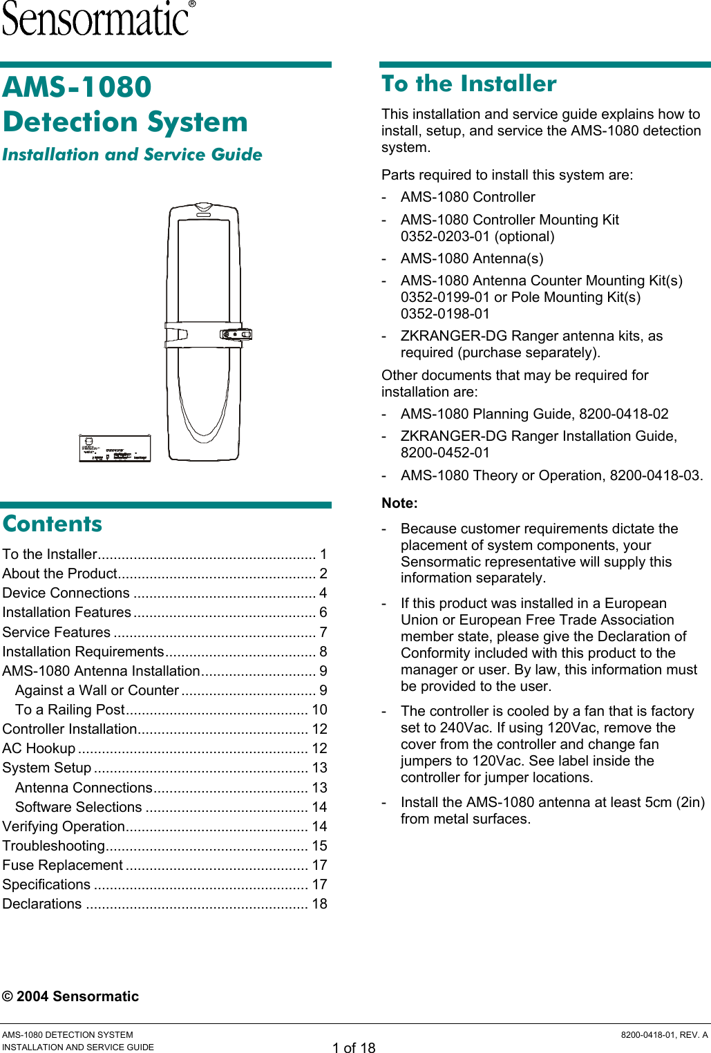
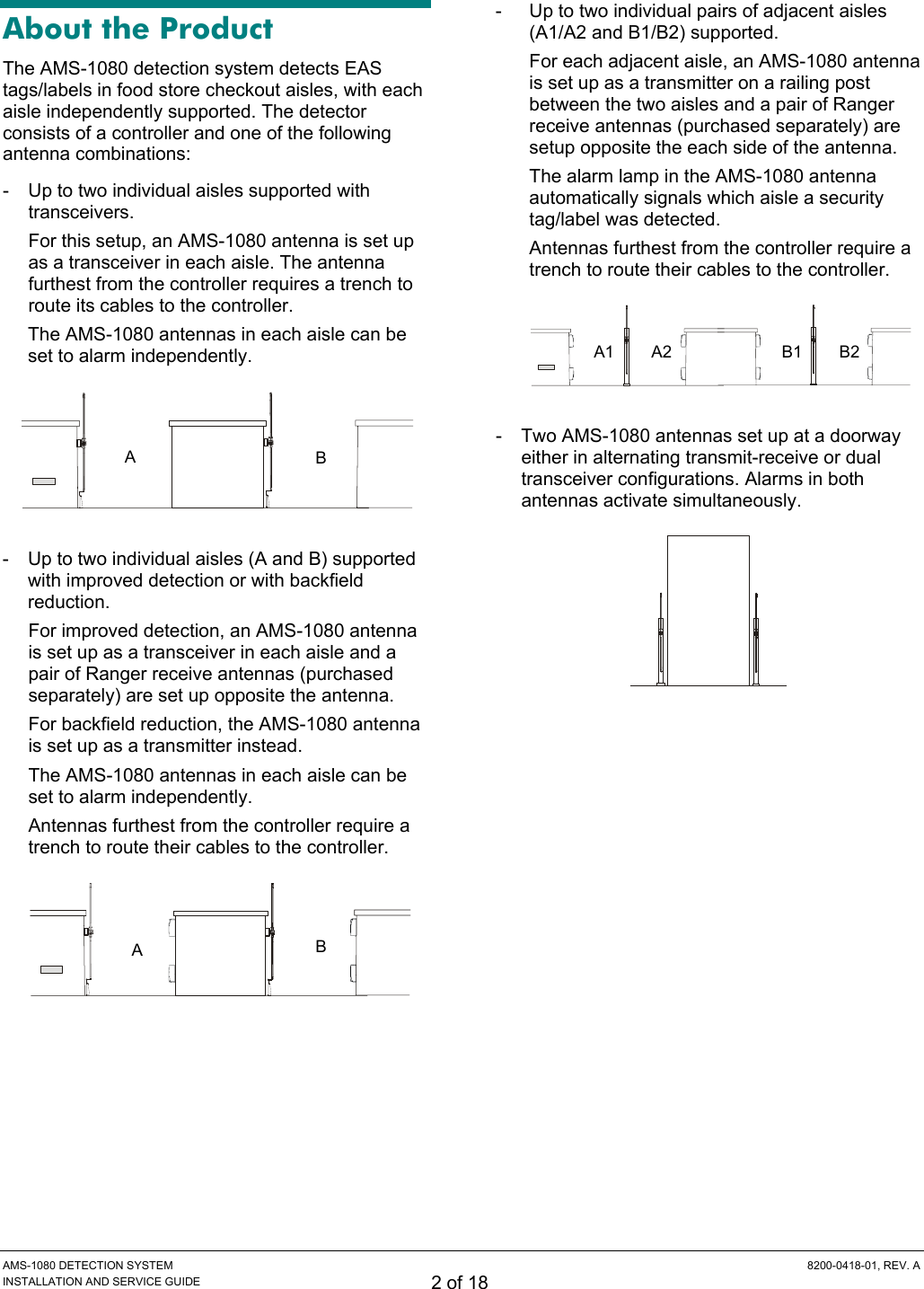
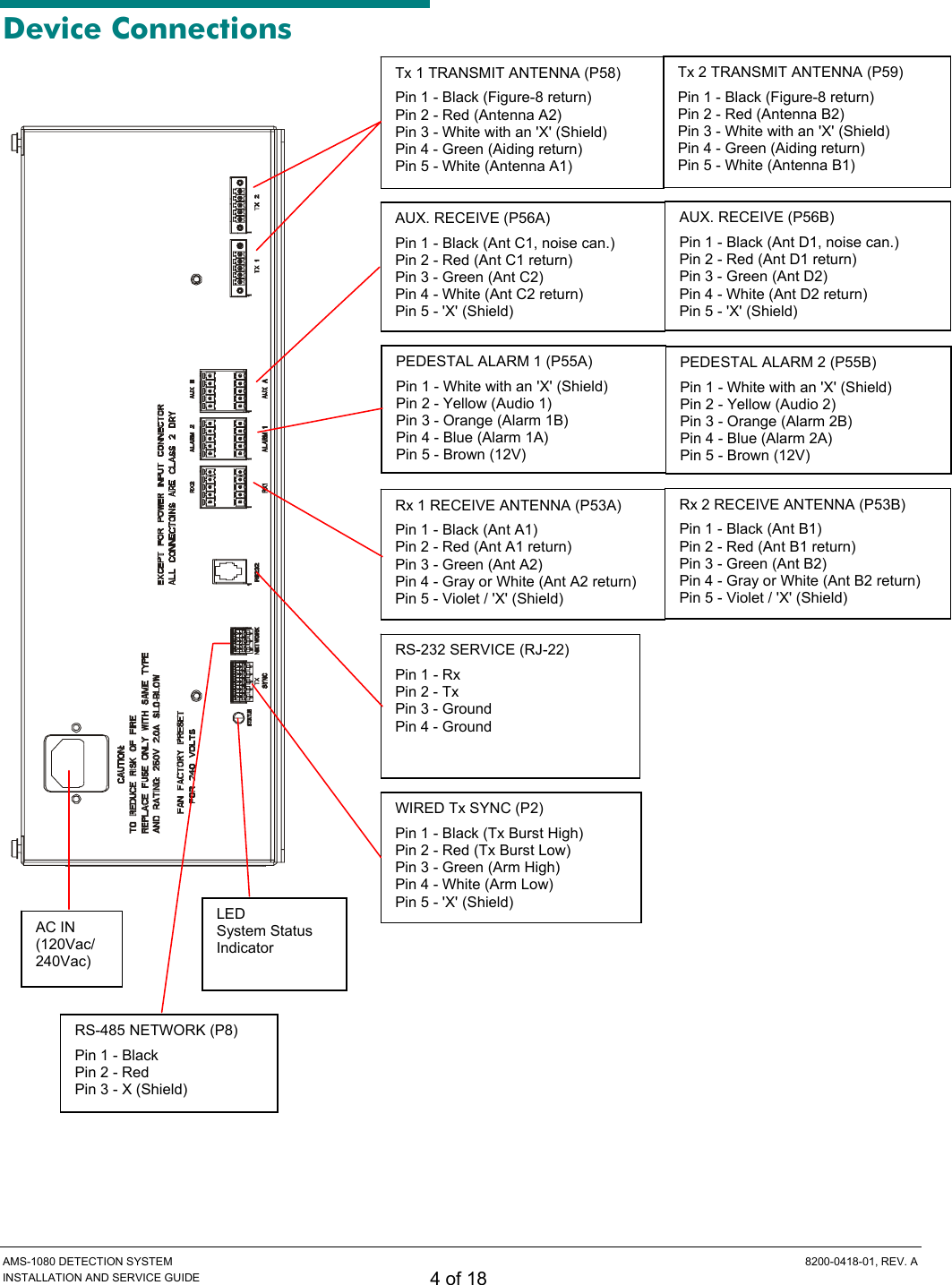
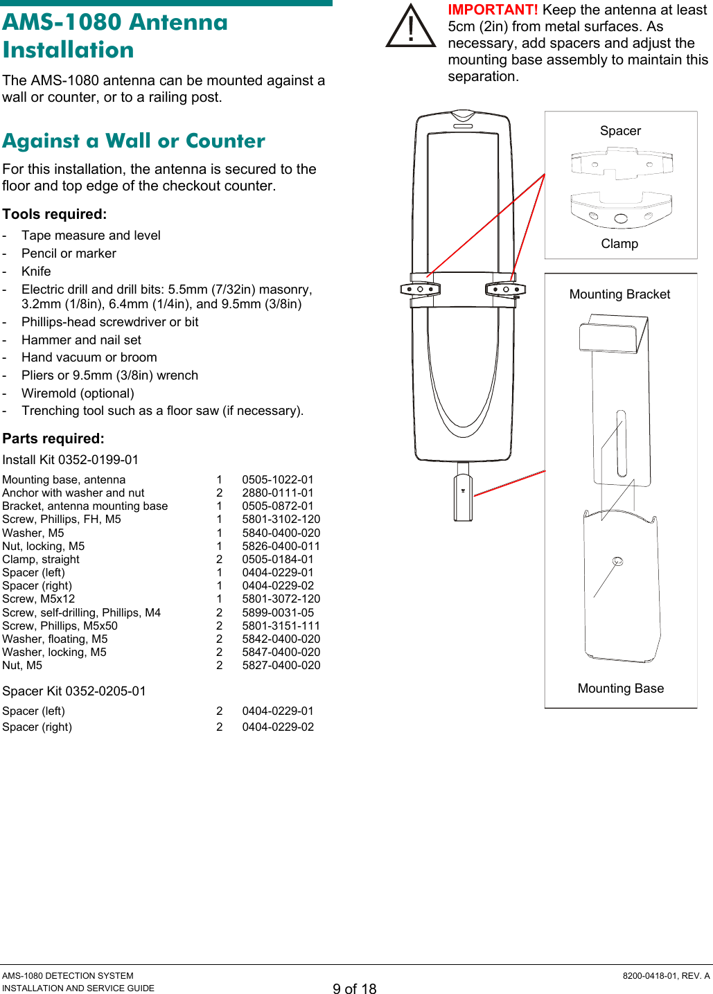
Tyco Safety Sensormatic AMS1080 ANTI THEFT DEVICE User Manual AMS 1080 Detection System

Tyco Safety Products/Sensormatic ANTI THEFT DEVICE AMS 1080 Detection System

USERS MANUAL

 AMS-1080 DETECTION SYSTEM  8200-0418-01, REV. A INSTALLATION AND SERVICE GUIDE 1 of 18 AMS-1080  Detection System Installation and Service Guide     Contents To the Installer....................................................... 1 About the Product.................................................. 2 Device Connections .............................................. 4 Installation Features.............................................. 6 Service Features ................................................... 7 Installation Requirements...................................... 8 AMS-1080 Antenna Installation............................. 9 Against a Wall or Counter .................................. 9 To a Railing Post.............................................. 10 Controller Installation........................................... 12 AC Hookup .......................................................... 12 System Setup ...................................................... 13 Antenna Connections....................................... 13 Software Selections ......................................... 14 Verifying Operation.............................................. 14 Troubleshooting................................................... 15 Fuse Replacement .............................................. 17 Specifications ...................................................... 17 Declarations ........................................................ 18   © 2004 Sensormatic To the Installer This installation and service guide explains how to install, setup, and service the AMS-1080 detection system. Parts required to install this system are: - AMS-1080 Controller -  AMS-1080 Controller Mounting Kit  0352-0203-01 (optional) - AMS-1080 Antenna(s) -  AMS-1080 Antenna Counter Mounting Kit(s) 0352-0199-01 or Pole Mounting Kit(s) 0352-0198-01 -  ZKRANGER-DG Ranger antenna kits, as required (purchase separately). Other documents that may be required for installation are: -  AMS-1080 Planning Guide, 8200-0418-02 -  ZKRANGER-DG Ranger Installation Guide, 8200-0452-01 -  AMS-1080 Theory or Operation, 8200-0418-03. Note:  - Because customer requirements dictate the placement of system components, your Sensormatic representative will supply this information separately. -  If this product was installed in a European Union or European Free Trade Association member state, please give the Declaration of Conformity included with this product to the manager or user. By law, this information must be provided to the user. -  The controller is cooled by a fan that is factory set to 240Vac. If using 120Vac, remove the cover from the controller and change fan jumpers to 120Vac. See label inside the controller for jumper locations. -  Install the AMS-1080 antenna at least 5cm (2in) from metal surfaces.
 AMS-1080 DETECTION SYSTEM  8200-0418-01, REV. A INSTALLATION AND SERVICE GUIDE 2 of 18 About the Product The AMS-1080 detection system detects EAS tags/labels in food store checkout aisles, with each aisle independently supported. The detector consists of a controller and one of the following antenna combinations: -  Up to two individual aisles supported with transceivers. For this setup, an AMS-1080 antenna is set up as a transceiver in each aisle. The antenna furthest from the controller requires a trench to route its cables to the controller. The AMS-1080 antennas in each aisle can be set to alarm independently.  -  Up to two individual aisles (A and B) supported with improved detection or with backfield reduction. For improved detection, an AMS-1080 antenna is set up as a transceiver in each aisle and a pair of Ranger receive antennas (purchased separately) are set up opposite the antenna. For backfield reduction, the AMS-1080 antenna is set up as a transmitter instead. The AMS-1080 antennas in each aisle can be set to alarm independently. Antennas furthest from the controller require a trench to route their cables to the controller.  -  Up to two individual pairs of adjacent aisles (A1/A2 and B1/B2) supported. For each adjacent aisle, an AMS-1080 antenna is set up as a transmitter on a railing post between the two aisles and a pair of Ranger receive antennas (purchased separately) are setup opposite the each side of the antenna. The alarm lamp in the AMS-1080 antenna automatically signals which aisle a security tag/label was detected. Antennas furthest from the controller require a trench to route their cables to the controller.  -  Two AMS-1080 antennas set up at a doorway either in alternating transmit-receive or dual transceiver configurations. Alarms in both antennas activate simultaneously.  A  B A  B A1 A2  B1 B2
 AMS-1080 DETECTION SYSTEM  8200-0418-01, REV. A INSTALLATION AND SERVICE GUIDE 3 of 18 Basic Operation The AMS-1080 detector deters theft by activating an alarm when it detects the unique response of an active Ultra•Max hard plastic tag or disposable label. To detect a tag/label, AMS-1080 antenna(s) connected to the controller emit a magnetic field close to the tag/label’s natural frequency causing it to vibrate or “ring” at the frequency of the field. When the field is removed, energy in the tag/label dissipates causing an exponential ring down. The AMS-1080 antenna(s)—and ferrite (Ranger) antennas, if used—pick up incoming signals and send them to the controller which processes them to determine if they are indicative of ring down. If they are, then the controller activates an audio/visual alarm indicator at the top of the AMS-1080 antenna that detected the tag/label. When the AMS-1080 antenna is positioned between two adjacent checkout lanes, the visual alarm indicator can be set to indicate the aisle where the active tag was detected. AMS-1080 Controller Features The AMS-1080 controller features the following: -  Independent Tx and Rx connections that  support two transmitters and four receivers -  Supports up to two noise canceling coils -  Controls pedestal alarms -  Has “ac line synchronization” and “tag too close” functions. -  Supports wired transmitter synchronization -  Is adjusted either on-site or remotely using a laptop computer and AMS-1080 service configurator software -  Built-in mounting flange enables it to mount vertically to a wall or inside the checkout counter. The controller can also rest on a shelf. AMS-1080 Antenna Features The AMS-1080 antenna features the following: -  Emits the detection field and receives the tag/label signal -  Figure “O” and Figure “8” transmit coils in the antenna combine to produce a field that alternates between the top and bottom of the antenna. These coils can also be set for maximum field in the top of the antenna only or the bottom of the antenna only. Maximum operating current is 15A -  Mounts to the side of a wall or counter, or to a railing post using hardware supplied -  Has an alarm lamp for each side of the antenna -  Has a “transmitter on” lamp that lights when the transmitter is on -  Has two hardwired cables that connect to the controller. Cable length is 7.6m (25ft). DO NOT CUT! Shorter cables can reduce operating performance. Ranger Antenna Features -  Only receives the tag/label signal -  Mounts to a wall or counter opposite the AMS-1080 antenna -  These ferrite antennas connect together as a pair and have a hardwired cable that connects to a “Auxiliary Receive” connector on the controller.
 AMS-1080 DETECTION SYSTEM  8200-0418-01, REV. A INSTALLATION AND SERVICE GUIDE 4 of 18 Device Connections      PEDESTAL ALARM 1 (P55A) Pin 1 - White with an 'X' (Shield) Pin 2 - Yellow (Audio 1) Pin 3 - Orange (Alarm 1B) Pin 4 - Blue (Alarm 1A) Pin 5 - Brown (12V) Tx 1 TRANSMIT ANTENNA (P58) Pin 1 - Black (Figure-8 return) Pin 2 - Red (Antenna A2) Pin 3 - White with an 'X' (Shield) Pin 4 - Green (Aiding return) Pin 5 - White (Antenna A1) Tx 2 TRANSMIT ANTENNA (P59) Pin 1 - Black (Figure-8 return) Pin 2 - Red (Antenna B2) Pin 3 - White with an 'X' (Shield) Pin 4 - Green (Aiding return) Pin 5 - White (Antenna B1) AUX. RECEIVE (P56A) Pin 1 - Black (Ant C1, noise can.) Pin 2 - Red (Ant C1 return) Pin 3 - Green (Ant C2) Pin 4 - White (Ant C2 return) Pin 5 - 'X' (Shield) AUX. RECEIVE (P56B) Pin 1 - Black (Ant D1, noise can.) Pin 2 - Red (Ant D1 return) Pin 3 - Green (Ant D2) Pin 4 - White (Ant D2 return) Pin 5 - 'X' (Shield) PEDESTAL ALARM 2 (P55B) Pin 1 - White with an 'X' (Shield) Pin 2 - Yellow (Audio 2) Pin 3 - Orange (Alarm 2B) Pin 4 - Blue (Alarm 2A) Pin 5 - Brown (12V) Rx 1 RECEIVE ANTENNA (P53A) Pin 1 - Black (Ant A1) Pin 2 - Red (Ant A1 return) Pin 3 - Green (Ant A2) Pin 4 - Gray or White (Ant A2 return) Pin 5 - Violet / 'X' (Shield) Rx 2 RECEIVE ANTENNA (P53B) Pin 1 - Black (Ant B1) Pin 2 - Red (Ant B1 return) Pin 3 - Green (Ant B2) Pin 4 - Gray or White (Ant B2 return) Pin 5 - Violet / 'X' (Shield) RS-232 SERVICE (RJ-22) Pin 1 - Rx Pin 2 - Tx Pin 3 - Ground Pin 4 - Ground RS-485 NETWORK (P8) Pin 1 - Black Pin 2 - Red Pin 3 - X (Shield) WIRED Tx SYNC (P2) Pin 1 - Black (Tx Burst High) Pin 2 - Red (Tx Burst Low) Pin 3 - Green (Arm High) Pin 4 - White (Arm Low) Pin 5 - 'X' (Shield) AC IN (120Vac/ 240Vac) LED  System Status Indicator
 AMS-1080 DETECTION SYSTEM  8200-0418-01, REV. A INSTALLATION AND SERVICE GUIDE 5 of 18 Transmit Antenna (Tx1, Tx2) These two connectors each receive a transmit cable from an AMS-1080 antenna. Receive Antenna (Rx1, Rx2, Aux A, Aux B) Connectors Rx1 and Rx2 each receive a receive cable from an AMS-1080 antenna or from a ferrite (Ranger) antenna. Connectors Aux A and Aux B each receive a cable only from a ferrite antenna. Each connector has a Coil 1 input (top of pedestal) and a Coil 2 input (bottom of pedestal). These connectors default to Rx function. Any adjustment to default settings must be saved in the controller for use on the next power cycle or system reset. When using noise coils, note the following: -  A noise coil is used to cancel specific noise interfering with detector operation. -  Noise coils only connect to the Coil 1 input of the Aux A or Aux B connectors on the controller. -  To accept a noise coil, the Coil 1 part of each auxiliary input must be reconfigured to noise canceling mode using the service configurator. -  By moving a noise coil around while monitoring power levels on the service configurator, a location can be found where noise cancellation is best. This is where the coil is likely to be installed. -  The location for noise coil installation must be practical as well as yield satisfactory results. RS-232 Network (Service Connection) This 4-pin modular connector receives the cable from a modem or laptop computer used to communicate with the controller. RS-485 Network This connector supports network communication and Sensormatic alarm logging and traffic flow devices. Wired Tx Sync The wired Tx sync function is used to eliminate interference from nearby detectors and deactiva-tors. A wired sync device connected to this port is automatically used as the timing reference for system functions. Note: The controller also provides for slower sequencer level synchronization to allow two antennas to be placed next to each other when driven by different controllers.
 AMS-1080 DETECTION SYSTEM  8200-0418-01, REV. A INSTALLATION AND SERVICE GUIDE 6 of 18 Installation Features Controller - Ac synchronization - Transmitter current control -  Integrated mounting flange to mount it to a vertical surface inside the checkout counter. Antenna -  7.6m (25ft) Tx burial rated cable -  7.6m (25ft) Rx burial rated cable -  Mounts to the checkout counter or pole -  No antenna tuning required. Auto Synchronization Auto synchronization occurs during power up or system reset. Auto sync can have different outcomes depending on whether or not nearby EAS transmitters are detected, they are properly aligned to the ac-derived timing of the controller, or too much ambient noise exists. No transmitters detected. During initialization, the controller determines if EAS transmitters are nearby. If none are found, transmitter delay is set to zero if this is the initial power on, or set to the value stored in the controller if not the initial power on. Transmitters detected: -  Transmitters detected and aligned. If transmitters are correctly aligned, the transmitter delay is calculated and stored in the controller for reference. -  Transmitters detected and not aligned. If transmitters are not aligned, the transmitter delay is set to zero if this is the first power on of the controller, or set according to the value stored the controller if not the initial power on. Too much ambient noise. During initialization, the controller locates other nearby EAS transmitters. -  If ambient noise prevents the controller from locating nearby EAS controllers and if this is the first power on of the controller, transmitter delay is set to zero. -  If this is not the first power on of the controller, the zero crossing delay stored in the controller is used. Note: The controller stores the zero crossing delay for when the controller could not determine a reliable lock during subsequent power cycles. Instead of using zero for the delay, the controller uses the stored zero crossing delay. Wired Synchronization If a wired Tx sync device is connected to the controller, the controller automatically uses its signal as the timing reference instead of the ac line. The service configurator indicates that wired sync is active. No Antenna Tuning AMS-1080 antennas are sealed at the factory. No tuning is necessary. Transmitter Current Control The controller checks current in each transmitter.  If current reaches a pre-determined level, the controller indicates current is excessive and which antenna is affected. The transmitter also shuts down for one second and then resumes. Antenna and Controller Mounting The AMS-1080 antenna can mount to the side of a wall or counter, or to a railing post in the checkout aisle. The controller has a built-in flange used to attach the controller to metal, wood, or drywall using suitable hardware. The wall and hardware must support 13.3kg (29.4 lbs) or four times the weight of the controller assembly.
 AMS-1080 DETECTION SYSTEM  8200-0418-01, REV. A INSTALLATION AND SERVICE GUIDE 7 of 18 Service Features Service features are as follows: - Laptop computer service configurator - Internal diagnostics -  LED system status indicator -  Remote diagnostics via modem, Ethernet, or RS485 network. “Tag Too Close” Function Using the service configurator, the “tag-too-close” function can be selected to help prevent false alarms. With this function selected, the red lamp on top of the antenna blinks twice every four seconds for one minute when the system detects one or more stationary tags or labels are too close to it. The lamp goes out when these tags/labels are moved away from the system.  Tagged items must be kept at least 1.5m (5ft) away from all sides of the antenna. Service Configurator Software Operating software required: Windows® 95, 98, NT, 2000, or XP. Service configurator software downloaded to a laptop computer is required to setup and troubleshoot the controller. The service configurator enables you to: - Set antenna configurations -  Customize detection for each antenna -  Monitor transmit and noise levels from each antenna -  Monitor transmit current from each antenna -  Customize alarm setup -  Turn off transmitters -  Monitor temperature inside the controller -  Download new software features/updates to flash memory -  Provide a system error report. Note: Special tools are not required when installing the controller as long as antennas are installed in a reasonable noise environment and local transmitters are properly adjusted. Note: If default settings are changed, you do not need to turn the controller off and on to store them. Internal Diagnostics -  The service configurator displays the operating current for each antenna. Operating current is 15A peak for European or non-European countries. -  The service configurator displays ambient temperature within the controller. -  The hardware supports software with a remote command to reset the system. -  Hardware within the controller protects it from runaway software. LED System Status Indicator An LED system status indicator on the controller indicates the following: -  Green flashing (system on and okay) -  Yellow flashing (performance downgraded; service recommended) -  Red flashing in a particular sequence (fault detected, call for service) The number of red flashes identifies a digit in a two-digit alert code (for example, four flashes is the number four). The start of an alert code is indicated by a long LED interval. Then the first digit of the code occurs, followed by a short delay, followed by the second digit. Alert codes are listed on page 15. Remote Diagnostics via an Ethernet or RS-485 Network Using a service laptop, service personnel can dial-up and connect to a network of controllers to troubleshoot problems and change controller parameters (see page 16).
 AMS-1080 DETECTION SYSTEM  8200-0418-01, REV. A INSTALLATION AND SERVICE GUIDE 8 of 18 Installation Requirements Verifying Equipment and Unpacking -  Verify that all equipment has arrived. Ensure the system configuration is correct for the installation site. -  Unpack major components in a back room. At the install site, lay out parts in the order you will need them. Do not clutter the aisle or cause a trip hazard. Installer/Contractor -  Have electrical work comply with the latest national electrical code, national fire code, and all applicable local codes and ordinances. -  Coordinate work with other trades to avoid interference. -  Verify existing site conditions and coordinate with the owner’s representative and appropriate utilities as required. -  Obtain copies of all related plans, specifications, shop drawings and addenda to schedule and coordinate related work. -  Thoroughly review the project to ensure that all work meets or exceeds the above requirements. Bring alleged discrepancies to the attention of Sensormatic Electronics. Controller Requirements -  The controller has a built-in flange used to attach the controller to metal, wood, or drywall using suitable hardware. The wall and hardware must support 13.3kg (29.4 lbs) or four times the weight of the controller assembly. -  Do not mount controller with its fan facing up. The fan must be set to the operating voltage using jumpers inside the controller. WARNING! Do not install this device where highly combustible or explosive products are stored or used. AMS-1080 Antenna Requirements WARNING! Do not install this device where highly combustible or explosive products are stored or used. CAUTIONS: -  Each AMS-1080 antenna has a silver label on one of its bottom side panels. This label must face the counter for single aisle installations, or “Aisle A1 or B1” for dual-aisle installations. -  When mounting the controller, power cord, connectors and fan must face down. -  Antennas furthest from the controller require a trench to route cables to the controller. -  Keep the surface of the AMS-1080 antenna at least 5cm (2in) from the surface of a metal-sided counter. -  Cables are 7.6m (25ft). DO NOT CUT! Shorter cables can reduce operating performance. Equipment Required Basic setup requires the following equipment: • AMS-1080 controller •  AMS-1080 antennas with counter mount  or pole mount hardware •  Ranger antennas (optional) •  Hard tag (non-deactivateable Ultra•Max tag) •  Ultra•Max low energy labels. Advanced setup requires the following additional equipment: • Laptop with Windows® 95, 98, NT, 2000, or XP operating software •  RS-232 Ultra•Max programming cable • Service configurator software.  !!
 AMS-1080 DETECTION SYSTEM  8200-0418-01, REV. A INSTALLATION AND SERVICE GUIDE 9 of 18 AMS-1080 Antenna Installation The AMS-1080 antenna can be mounted against a wall or counter, or to a railing post. Against a Wall or Counter For this installation, the antenna is secured to the floor and top edge of the checkout counter. Tools required: -  Tape measure and level -  Pencil or marker - Knife -  Electric drill and drill bits: 5.5mm (7/32in) masonry, 3.2mm (1/8in), 6.4mm (1/4in), and 9.5mm (3/8in)   -  Phillips-head screwdriver or bit   -  Hammer and nail set   -  Hand vacuum or broom  -  Pliers or 9.5mm (3/8in) wrench - Wiremold (optional) -  Trenching tool such as a floor saw (if necessary). Parts required: Install Kit 0352-0199-01 Mounting base, antenna  1  0505-1022-01 Anchor with washer and nut  2  2880-0111-01 Bracket, antenna mounting base  1  0505-0872-01 Screw, Phillips, FH, M5  1  5801-3102-120 Washer, M5  1  5840-0400-020 Nut, locking, M5  1  5826-0400-011 Clamp, straight  2  0505-0184-01 Spacer (left)  1  0404-0229-01 Spacer (right)  1  0404-0229-02 Screw, M5x12  1  5801-3072-120 Screw, self-drilling, Phillips, M4  2  5899-0031-05 Screw, Phillips, M5x50  2  5801-3151-111 Washer, floating, M5  2  5842-0400-020 Washer, locking, M5  2  5847-0400-020 Nut, M5   2  5827-0400-020 Spacer Kit 0352-0205-01 Spacer (left)  2  0404-0229-01 Spacer (right)  2  0404-0229-02   IMPORTANT! Keep the antenna at least 5cm (2in) from metal surfaces. As necessary, add spacers and adjust the mounting base assembly to maintain this separation.    Clamp Mounting Bracket Mounting Base Spacer
 AMS-1080 DETECTION SYSTEM  8200-0418-01, REV. A INSTALLATION AND SERVICE GUIDE 10 of 18 PROCEDURE 1.  A label is on a bottom side panel of the AMS-1080 antenna. The label must face the counter. 2.  Attach antenna clamps. a.  Position clamps in the spaces on the antenna designated for them. b.  A right and left spacer are provided. Press the adhesive side of a spacer against each clamp to hold them in place. Note: Each spacer has a cable notch; cables exiting the antenna pass through this notch. If the antenna must be further from the wall or counter, add more spacers. IMPORTANT! Keep the antenna at least 5cm (2in) from metal surfaces. 3.  Mark mounting-screw hole locations. a.  Build the mounting base assembly by attaching the antenna mounting bracket to the top of the mounting base using an M5 screw, washer, and locking nut. With the mounting base assembly in its installation position, the bends at the top of the bracket must face away from the counter. b.  To place antenna clamps at the proper mounting height, temporarily insert the top of the mounting base assembly into the slot in the bottom of the antenna. Then holding the antenna clamps against the counter, and with the antenna level, mark hole locations: •  In the counter for screws that will secure the clamps, •  Directly behind the cable notch in the spacer where cables exit the antenna, •  On the floor for two anchors that will secure the mounting base. c.  Remove the antenna and mounting base assembly. 4.  Drill mounting holes. a.  Using a 5.5mm (7/32in) masonry bit, drill two holes in the floor 54mm (2-1/8in) deep for the anchor bolts. CAUTION: If carpet exists, use a knife to remove it from under the mounting base to prevent carpet runs caused by drilling. IMPORTANT! Holes more than 60mm (2-3/8in) deep or less than 50mm (2in) deep may not secure anchor bolts. b.  Directly behind the cable notch in the spacer where cables exit the antenna, drill a 16mm (5/8in) access hole in the checkout counter for antenna cables to go to the controller. c.  Drill holes for screws that will secure clamps. Note: If using self-drilling screws in sheet metal, 3.2mm (1/8in) pilot holes may be needed. Otherwise, drill a 6.4mm (1/4in) hole for an M5 machine screw, washer, and nut. 5.  Install the mounting base assembly. a.  Remove the nut and washer from each anchor and insert the anchor into a hole until it contacts bottom. b.  Using a hammer and nail set, strike the anchor several times to secure it. c.  Secure the mounting base assembly to the two protruding anchors using the washer and nut just removed. Tighten the hardware. 6.  Again, set the antenna assembly onto the mounting base and ensure the antenna is level. 7.  Route antenna cables through the hole to the controller. Connect antenna cables to the controller. DO NOT CUT CABLES! 8.  Secure clamps to the wall or counter using self-drilling screws or M5 machine screws, washers, and nuts supplied. 9.  If used, install Ranger antennas; otherwise, see “System Setup” on page 13.
 AMS-1080 DETECTION SYSTEM  8200-0418-01, REV. A INSTALLATION AND SERVICE GUIDE 11 of 18 To a Railing Post For this installation, the antenna is secured to a railing post between two adjacent aisles.   Tools required: -  Two 3.2mm (1/8in) Allen wrench hex drivers - Tape measure -  Pencil or marker -  Electric drill and drill bits: 5.5mm (7/32in) and 9.5mm (3/8in) -  Phillips-head screwdriver or bit -  Hand vacuum or broom -  Trenching tool, such as a floor saw Parts required: Install Kit 0352-0198-01 Bracket, pole  4  0505-0570-01 Bushing, pole  4  0505-0571-01 Appliqué 4 0505-0572-01 Screw, M, PHP, M5x16  2  5801-3081-120 Washer, FL, M5  4  5840-0400-022 Nut, M5  2  5827-0400-020 Clamp, cable, 1/2in width, SS  2  6010-0122-01 PROCEDURE 1.  Saw a 6.4mm (1/4in) wide, 19mm (3/4in) deep trench into the floor between the railing post and the counter where the controller is to be located. 2.  With the label on the bottom side panel of the antenna facing Aisle A1 or Aisle B1, with the antenna parallel to the line of traffic and its bottom 17.8cm (7in) from the floor, drill a 16mm (5/8in) cable access hole in the railing post directly opposite where cables exit the antenna. CAUTION: Do not drill this hole through the other side of the post. 3.  Attach the pole bracket to the antenna. a.  Remove an M5x16 screw, washer, and nut from the pole bracket and loosen the strap, but be careful to keep the bracket assembly together. b.  Slide the pole bracket down the post to align the cable exit hole in the bracket with the cable access hole in the post. c.  Spread the bracket assembly. d.  Insert the pole bracket into the part of the antenna designated for it while routing antenna cables into the access hole, down inside the post, and into the trench. e.  Reattach the M5x16 screw, washer, and nut and tighten the assembly. f.  With its screw tucked inside the pole bracket, tighten the strap holding the bracket together.   4.  Remove the backing from the appliqué. Then affix the appliqué over its matching recess in the pole bracket to hide the hardware. 5.  Repeat steps 3 and 4 to install a second pole bracket about 15.2cm (6in) above the first. 6.  Route antenna cables through the trench to the controller. Connect antenna cables to the controller. DO NOT CUT CABLES! 7.  Install Ranger antennas. Screw Strap Remove hardware to attach 17.8cm (7in) Trench
 AMS-1080 DETECTION SYSTEM  8200-0418-01, REV. A INSTALLATION AND SERVICE GUIDE 12 of 18 Controller Installation Tools required: - Tape measure -  Pencil or marker -  Electric drill and drill bits: 5.5mm (7/32in) and 9.5mm (3/8in) -  Phillips-head screwdriver or bit -  Hand vacuum or broom Parts required:  Install Kit 0352-0203-01 Screw, self-drilling, M4, 8x25, PHP  4  5899-0031-01 PROCEDURE 1.  Set the controller on a shelf or mount it, with its fan facing down, to a vertical surface using the four self-drilling screws supplied. WARNING! The vertical surface must be able to support 13.3kg (29.4 lbs).  2.  Referring to the diagram on page 4, attach connectors to cables used for the installation. 3.  Plug cables into the appropriate  connectors on the controller. AC Hookup CAUTION: Fan voltage is factory set for 240Vac. If using 120Vac, remove the cover from the controller and change fan jumpers to 120Vac. See label inside the controller for jumper locations. PROCEDURE 1.  Choose a power cord for the country of use. Power cords come in .9m (3ft), 2.7m (9ft), 3.7m (12ft), and 4.6m (15ft) lengths. 2.  Plug in the power cord. The controller automatically senses the voltage (100-120Vac or 200-240Vac). No adjustments are required. WARNING—RISK OF ELECTRIC SHOCK! The ac power cord may carry 120Vac or 240Vac. CAUTION: When using a power cord, a socket-outlet must be installed near the controller and in an easily accessible location. Für Installationen mit einem Stromkabel muß die Steckdose an einem Standort installiert werden, welcher einfachen Zugang erlaubt. CAUTION: A 10A, 2-pole, ganged disconnect device, which also provides short circuit and overload protection, and has a minimum 3mm open circuit clearance, in accordance with the National Electric Code and applicable local codes must be installed by a licensed electrician at a location readily accessible to the equipment. Ein 10A, 2-poliges, gekoppeltes Ausschaltgerät, welches auch über einen Kurzschluß- sowie Überbelastungsschutz verfügt, und einen minimum 3mm offenen Schaltabstand aufweist, nach Übereinstimmung mit den Nationalen Elektrischen Regelungen sowie lokalen Regeln, muß an einem Standort installiert werden, welcher einfachen Zugang zum Gerät erlaubt.
 AMS-1080 DETECTION SYSTEM  8200-0418-01, REV. A INSTALLATION AND SERVICE GUIDE 13 of 18 System Setup Turn on the controller. Then connect antenna cables and select software parameters as follows for the type of antenna configuration installed. Antenna Connections -  AMS-1080 antenna set up as a transceiver.   Connect antenna cables as follows: Aisle  Antenna Cables  To Controller Port AMS-1080 Tx  Tx 1 A AMS-1080 Rx/Alarm  Rx 1/Alarm 1 AMS-1080 Tx  Tx 2 B AMS-1080 Rx/Alarm  Rx 2/Alarm 2 -  AMS-1080 antenna set up as a transceiver with a pair of Ranger antennas. -  AMS-1080 antenna set up as a transmitter for backfield reduction with a pair of Ranger antennas.   Connect antenna cables as follows: Aisle  Antenna Cables  To Controller Port AMS-1080 Tx  Tx 1 AMS-1080 Rx/Alarm  Rx 1/Alarm 1 A Ferrites (Rangers)  Aux A AMS-1080 Tx  Tx 2 AMS-1080 Rx/Alarm  Rx 2/Alarm 2 B Ferrites (Rangers)  Aux B  -  AMS-1080 antenna set up as a transmitter and positioned between two adjacent aisles for zone detection.  Connect antenna cables as follows: Aisle  Antenna Cables  To Controller Port AMS-1080 Tx  Tx 1 AMS-1080 Rx/Alarm  Alarm 1 only A1 Ferrites (Rangers)  Rx 1 A1/A2 A2 Ferrites (Rangers)  Aux A AMS-1080 Tx  Tx 2 AMS-1080 Rx/Alarm  Alarm 2 only B1 Ferrites (Rangers)  Rx 2 B1/B2 B2 Ferrites (Rangers)  Aux B -  Two AMS-1080 antennas set up at a doorway either in the transmit-receive or transceiver configuration.  Connect antenna cables as follows: Antenna  Antenna Cables  To Controller Port AMS-1080 Tx  Tx 1 Right AMS-1080 Rx/Alarm  Rx 1/Alarm 1 AMS-1080 Tx  Tx 2 Left AMS-1080 Rx/Alarm  Rx 2/Alarm 2 A B A1/A2 B1/B2  A1/A2 B1/B2 A B
 AMS-1080 DETECTION SYSTEM  8200-0418-01, REV. A INSTALLATION AND SERVICE GUIDE 14 of 18 Software Selections Note: Software parameters are selected using AMS-1080 service configurator software. Only selections pertaining to a basic system setup are covered here. For additional information on software parameters and how to use the configurator, click Help in the service configurator. On the service configurator, select the following for each aisle or doorway: Software Parameter  Select/Adjust System Configuration  See below* Aisle A/B  See below** Audio  Volume, Duration, and Inhibit Time. Enable Jammer Event Trigger if a 58kHz jammer is used. Lamp  Duration and Inhibit Time. Enable Jammer Event Trigger if a 58kHz jammer is used. Current Adjust  Set as required. Misc. Tx Settings  Ant A/B Polarity and Tx Frequency  *  Select “Individual Aisle Config” if AMS-1080 antenna(s) are to be set up in a checkout aisle.  Select “Alternating” or “Dual Transceiver” if AMS-1080 antenna(s) are to be set up at a doorway. “Alternating” enables two AMS-1080 antennas to alternate between transmit and receive with one antenna being the transmitter and the other the receiver. “Dual Transceiver” enables two AMS-1080 antennas to be transceivers. Both antennas alarm simultaneously. ** This selection is only available when “Individual Aisle Config” is selected. Set Aisle A or B to one of the following: a.  None (no antenna enabled, do not select). b.  Transceiver. Select if an AMS-1080 antenna is the only antenna to be used in the aisle. c.  Transceiver–Ferrite. Select if an AMS-1080 antenna is set up as a transceiver and two Ranger antennas set up as receivers in the aisle. d.  Backfield Reduction. Select if an AMS-1080 antenna is set up as a transmitter and two Ranger antennas set up as receivers in the aisle. e.  Dual Aisle Zone Detect. Select if an AMS-1080 antenna is set up as a transmitter on a railing post between two adjacent aisles with a pair of Ranger antennas in each aisle for alarm zone detection. The alarm lamp lights in the aisle the tag/label was detected in. Verifying Operation Check that the AMS-1080 antenna alarm lamp lights when a tag/label is passed through the checkout aisle, or if the system is covering adjacent aisles, that the lamp lights only in the aisle the tag/label was in. If the pick rate is acceptable, fill the cable trench. Installation is complete.
 AMS-1080 DETECTION SYSTEM  8200-0418-01, REV. A INSTALLATION AND SERVICE GUIDE 15 of 18 Troubleshooting System Status Alert Codes The Status LED on the controller displays system status alert codes. When an alert code occurs, the LED changes color and pattern. Red is used for serious alerts while yellow is used for those less serious. a.  The number of red flashes identifies a digit in a two-digit alert code (for example, four flashes is the number four). The start of an alert code is indicated by a long LED interval. Then the first digit of a two-digit error code occurs, followed by a short delay, followed by the second digit. b.  See the table opposite for the significance of the alert code. Most alert codes are automatically resolved. c.  Some codes can only be accessed using the service configurator. They are not displayed by the Status LED. d.  Alert codes are lost when the controller is reset. Code storage has a time stamp in days, hours, minutes, seconds, milliseconds/ ticks of when the system alert occurred. The following critical faults are backed with hardware support and provide the necessary action when encountered. -  Current fault 1 per channel -  Ambient temperature fault -  Primary current fault -  Secondary current fault -  Last resort current fault to maintain Class 2 wiring requirements. Alert codes repeat until the condition is resolved or a timer resets the system. Alert Codes Alert Code  Significance 11  Illegal Instruction  Return controller 12  Unimplemented Interrupt  Return controller 13  NVM Write Failed  Return controller 14  Invalid Device  Return controller 15  Sequence Table Error  Return controller 16  Out of Memory  Return controller 17  Undecided: No Split  Return controller 18  Watchdog: Task Reset  Return controller 21  AntA S/W Current Fault  Recoverable 22  AntB S/W Current Fault  Recoverable 25  H/W Current Fault  Recoverable 26  AntA Current Sense Fault  Recoverable 27  AntB Current Sense Fault  Recoverable 39 Sequence Table Mismatch  Recoverable 41  Missing Zero Crossing  Return controller 42  Wired Sync: Missing Signal  Recoverable 43 Temperature Fault  Recoverable 44  S/W Temperature Fault  Recoverable 45  PWM Fault  Return controller 46 Fan Fault  Recoverable 49  Realtime Error  Return controller 51  Autosetup Owner Timeout  Recoverable 52  Autosetup Release W/O Lock  Recoverable 53  Autosetup Buffer Overrun  Recoverable 54  Autosetup Mailbox Full  Recoverable 56  Notch Select Timeout  Recoverable 57  Window Select Timeout  Recoverable 58  Autosetup Illegal Owner  Recoverable 61 Detector Overrun  Recoverable 62  Alarm Mailbox Full  Recoverable 63  Host Comm Mailbox Full  Recoverable 64  Host Comm Mailbox Full  Recoverable 71  Host Comm Mailbox Full  Recoverable
 AMS-1080 DETECTION SYSTEM  8200-0418-01, REV. A INSTALLATION AND SERVICE GUIDE 16 of 18 Local Diagnostics The AMS-1080 controller enables you to troubleshoot and change controller parameters using your laptop computer and the AMS-1080 service configurator. The following hardware is required: • Laptop computer •  Service cable with a male RJ-10/22 phone connector on one end and a male RJ-11/12 connector on the other • DB-9-to-RJ-11/12 connector. How to Connect Cables 1.  Connect the DB-9-to-RJ-11/12 connector to the DB-9 serial port on your laptop computer. Only pins 2, 3, and 5 are used. 2.  Connect the RJ-11/J12 connector of the service cable to the DB-9 connector and the RJ-10/J22 connector on its other end to the RS-232 port (RJ-10/22) on the controller.  Remote Diagnostics The AMS-1080 controller enables you to use an RS-485 network to troubleshoot and change controller parameters from a remote site. To connect to the network, connect the laptop, modem and accessories as shown below.   DB9 RJ-11/J12 RJ-10/22 to  RS-232 port on controller DB-25 male to DB-9 male adapter Null modem adapter T adapter Modem RS-232/RS-485 converter Controller RS-485 portLaptop
 AMS-1080 DETECTION SYSTEM  8200-0418-01, REV. A INSTALLATION AND SERVICE GUIDE 17 of 18 Fuse Replacement The controller has two 2A, 250V slow-blow fuses in the IE320 ac receptacle.   1.  Pry the rectangular cover plate from the ac receptacle using a small slotted screwdriver. Two spring-loaded fuses should pop out. 2.  Replace the blown fuse (or fuses) with 2A, 250V slow-blow fuses (P/N 5111-0028-07).  Specifications Electrical POWER SUPPLY Primary input............................ 100-120Vac or 200-240Vac @ 50–60Hz Primary power fuse .................. 2A, 250V, slo-blow, hi-breaking Current draw ............................ <1.0Arms @ 120Vac Input power .............................. <100W TRANSMITTER Operating frequency................. 58kHz (±200Hz) Transmit burst duration ............ 1.6ms Transmit current maximum ...... 15A peak Burst Repetition Rate: Based on 50Hz ac.................... 75Hz or 37.5Hz Based on 60Hz ac.................... 90Hz or 45Hz RECEIVER Center frequency...................... 58kHz Environmental Ambient temperature................ 0°C to 50°C  (32°F to 122°F) Relative humidity...................... 0 to 90%  non-condensing Mechanical (AMS-1080 Controller) Length ...................................... 37.3cm (14.7in) Width........................................ 27.8cm (10.9in) Height....................................... 13.4cm (5.3in) Weight...................................... 3.33kg (7.34 lbs.) Mechanical (AMS-1080 Antenna) Thickness................................. 3.6cm (1.4in) Width........................................ 36.4cm (14.3in) Height....................................... 121.3cm (47.8in) Weight...................................... 5.2kg (11.5 lbs.) Fuses (2)
 AMS-1080 DETECTION SYSTEM  8200-0418-01, REV. A INSTALLATION AND SERVICE GUIDE 18 of 18 Declarations ASAISLE REG ID: AMS-1080 ANT ZKRANGER-DG REG ID: UM UPFAF Regulatory Compliance EMC...............................47 CFR, Part 15   EN 300330-1 U1.3.2 (2002) ETSI EN 300330-2 V1.1.1 (2001-06)   ETSI EN 301489-3 V 1.4.1 (2002-08)   ETSI EN 301489-1 V 1.4.1 (2002-08)  RSS210 Safety ............................UL 60950   CSA C22.2 No 60950  EN 60950 FCC COMPLIANCE: This equipment complies with Part 15 of the FCC rules for intentional radiators and Class A digital devices when installed and used in accordance with the instruction manual. Following these rules provides reasonable protection against harmful interference from equipment operated in a commercial area. This equipment should not be installed in a residential area as it can radiate radio frequency energy that could interfere with radio communications, a situation the user would have to fix at their own expense. EQUIPMENT MODIFICATION CAUTION: Equipment changes or modifications not expressly approved by Sensormatic Electronics Corporation, the party responsible for FCC compliance, could void the user's authority to operate the equipment and could create a hazardous condition. Other Declarations WARRANTY DISCLAIMER: Sensormatic Electronics Corporation makes no representation or warranty with respect to the contents hereof and specifically disclaims any implied warranties of merchantability or fitness for any particular purpose. Further, Sensormatic Electronics Corporation reserves the right to revise this publication and make changes from time to time in the content hereof without obligation of Sensormatic Electronics Corporation to notify any person of such revision or changes. LIMITED RIGHTS NOTICE: For units of the Department of Defense, all documentation and manuals were developed at private expense and no part of it was developed using Government Funds. The restrictions governing the use and disclosure of technical data marked with this legend are set forth in the definition of “limited rights” in paragraph (a) (15) of the clause of DFARS 252.227.7013. Unpublished - rights reserved under the Copyright Laws of the United States. TRADEMARK NOTICE: Sensormatic is a registered trademark of Sensormatic Electronics Corporation. Other product names mentioned herein may be trademarks or registered trademarks of Sensormatic or other companies. No part of this guide may be reproduced in any form without written permission from Sensormatic Electronics Corporation. MDR 08/2004

Navigation menu