Tyco Safety Sensormatic AMS9050 Anti-Pilferage Device User Manual users manual
Tyco Safety Products/Sensormatic Anti-Pilferage Device users manual
Contents
- 1. users manual
- 2. Users Manual
users manual
AMS-9050 CONTROLLER 8200-0537-02, REV. B
INSTALLATION AND SERVICE GUIDE 1 of 16
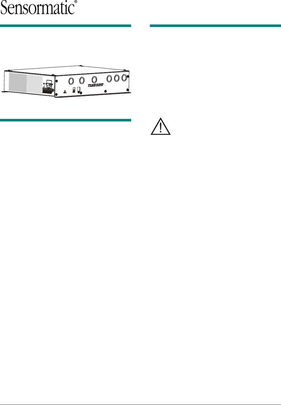
AMS-9050 Controller
Installation and Service Guide
ZE9050
Contents
To the Installer....................................................... 1
About the Product.................................................. 2
Device Connections ........................................... 3
Installation Features........................................... 7
Service Features................................................ 8
Installation Requirements...................................... 9
Controller Installation........................................... 11
Troubleshooting................................................... 13
Fuse Replacement .............................................. 15
Specifications ...................................................... 15
Declarations ........................................................ 16
© 2006 Sensormatic Electronics Corp.
To the Installer
This installation and service guide explains how to
install, setup, and service the AMS-9050 controller.
Parts required to install this system are:
- AMS-9050 controller
- AMS-1100/1101 exit antenna(s) or
AMS-1080 aisle antenna(s)
Other documents that may be required for
installation are:
- AMS-9050 Planning Guide, 8200-0537-01.
Note: There may be installation
restrictions on antennas in certain
countries. See antenna installation guides
for restrictions, if any.
Regulatory Restriction: This device is
only intended to be installed as described
in the installation guide.
- Because customer requirements dictate the
placement of system components, your
Sensormatic representative will supply this
information separately.
- If this product was installed in a European
Union or European Free Trade Association
member state, please give the Declaration of
Conformity included with this product to the
manager or user. By law, this information must
be provided to the user.
- Because of the number of antennas and
accessories that can connect to this controller,
methodically install this system to avoid
problems. See “System Setup” in this guide for
guidance on how to setup antennas.

AMS-9050 CONTROLLER 8200-0537-02, REV. B
INSTALLATION AND SERVICE GUIDE 2 of 16
About the Product
The AMS-9050 controller is part of an EAS system
that:
- Includes pedestal type antennas.
- Deters theft by activating an alarm when it
detects the unique response of an active
Ultra•Max hard plastic tag or disposable label
when its signal is picked up by an antenna.
Installation Features
- Built-in mounting flange enables the controller
to mount to a wall or inside a checkout counter.
The controller can also rest on a shelf or attach
to a ceiling.
- Six knockouts receive exposed cables or cables
in conduit. Knockouts are available for Class 2
wiring from antennas and low voltage devices.
Setup Features
- Supports various pedestal antennas used to
detect tags/labels at exits or in food store
checkout aisles.
- Supports up to four AMS-1100/-1101 unicoil
transceiver exit pedestals, or up to four AMS-
1080 aisle pedestals, each with separate
transmit and receive coils.
- Antennas can be set up as four transceivers,
or four transmit/receive pairs, or combina-
tions of both using a laptop computer and
ADS 4 service configurator software. Two
receivers can be noise canceling coils.
Automatic configuration is available for the
commonly used system configurations.
- Antenna coils can be set for phase flipping
(default), aiding, or figure-8 operation.
Note: Phase flipping is unavailable when
noise canceling coils are used.
- Supports auto synchronization
- Supports the following alarm devices:
- Built-in alarm in the antenna (if used)
- Up to two externally-powered remote alarms
- Externally-powered Sensormatic alarm
management or traffic flow device
- Up to two relays for devices such as security
cameras.
- Connection for hardwired sync and transmit
inhibit function.
- Supports RS-232 (local diagnostics) and RS-
485 (remote diagnostics).
- Supports RS-485 network communication to
antennas (if supported by antenna).
Service Features
- The controller detaches from its cable access
panel to facilitate servicing.
- System status LED on controller displays error
codes used for troubleshooting.
Basic Operation and Setup
To detect a tag:
- Antenna(s) connected to the controller emit a
58kHz magnetic field close to the tag/label’s
natural frequency causing it to vibrate or “ring”
at the frequency of the field. When the field is
removed, energy in the tag/label dissipates
causing an exponential ring down.
- The controller processes signal inputs picked up
by the antennas to determine if they are
indicative of a tag/label signal.
- If the controller detects a tag/label signal, it
activates audio-visual indicators on each
antenna that picked up the signal and/or
activates remote alarm devices, if used.
ADS 4 service configurator software enables the
field technician to:
- Adjust the system
- Synchronize the controller to other EAS
systems using the ac line, or wired
synchronization
- Monitor and adjust for noise interference and
use of a 58kHz jammer device
- Download software application updates
- Monitor internal temperature of the controller
- Perform diagnostic tests and read error codes.
AMS-9050 CONTROLLER 8200-0537-02, REV. B
INSTALLATION AND SERVICE GUIDE 3 of 16
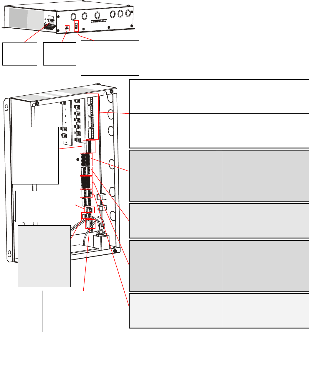
Device Connections
RS-232 SERVICE (J2)
Pin 1 - Rx
Pin 2 - Tx
Pin 3 - Ground
Pin 4 - Ground
AC IN
(120Vac/
240Vac)
System
Status LED
RS-485 NETWORK (P8)
Pin 1 - Black
Pin 2 - Red
Pin 3 - X (Shield)
WIRED Tx SYNC (P2)
Pin 1 - Black (Tx Burst High)
Pin 2 - Red (Tx Burst Low)
Pin 3 - Green (Arm High)
Pin 4 - White (Arm Low)
Pin 5 - 'X' (Shield)
RMT ALARM 1 (P64)
Pin 1 - Orange
Pin 2 - Violet
Pin 3 - X (Shield)
RMT ALARM 2 (P63)
Pin 1 - Orange
Pin 2 - Violet
Pin 3 - X (Shield)
RELAYS (P54)
Pin 1 - Common 1
Pin 2 - NC 1
Pin 3 - NO 1
Pin 4 - ‘X’ (shield)
Pin 5 - Common 2
Pin 6 - NC 2
Pin 7 - NO 2
Pin 8 - ‘X’ (shield)
Tx A TRANSMIT ANTENNA (P58)
Pin 1 - Black (Figure-8 return)
Pin 2 - Red (Antenna A2)
Pin 3 - Silver (Shield)
Pin 4 - Green (Aiding return)
Pin 5 - White (Antenna A1)
Tx B TRANSMIT ANTENNA (P59)
Pin 1 - Black (Figure-8 return)
Pin 2 - Red (Antenna B2)
Pin 3 - Silver (Shield)
Pin 4 - Green (Aiding return)
Pin 5 - White (Antenna B1)
Tx C TRANSMIT ANTENNA (P88)
Pin 1 - Black (Figure-8 return)
Pin 2 - Red (Antenna C2)
Pin 3 - Silver (Shield)
Pin 4 - Green (Aiding return)
Pin 5 - White (Antenna C1)
Tx D TRANSMIT ANTENNA (P91)
Pin 1 - Black (Figure-8 return)
Pin 2 - Red (Antenna D2)
Pin 3 - Silver (Shield)
Pin 4 - Green (Aiding return)
Pin 5 - White (Antenna D1)
PEDESTAL ALARM C (P93)
Pin 1 - White with an 'X' (Shield)
Pin 2 - Yellow (Audio 3)
Pin 3 - Orange (Alarm 3)
Pin 4 - Blue (N/A)
Pin 5 - Brown (12V)
Pin 6 - Black (PED485_LO)
Pin 7 - Red (PED485_HI)
Pin 8 - Green (TX_INHIBIT 1)
PEDESTAL ALARM D (P100)
Pin 1 - White with an 'X' (Shield)
Pin 2 - Yellow (Audio 4)
Pin 3 - Orange (Alarm 4)
Pin 4 - Blue (N/A)
Pin 5 - Brown (12V)
Pin 6 - Black (PED485_LO)
Pin 7 - Red (PED485_HI)
Pin 8 - Green (TX_INHIBIT 1)
Rx C RECEIVE ANT (P99)
Pin 1 - Black (Ant C1)
Pin 2 - Red (Ant C1 return)
Pin 3 - Green (Ant C2)
Pin 4 - Gray or White (Ant C2 return)
Pin 5 - Violet / 'X' (Shield)
Rx D RECEIVE ANT (P103)
Pin 1 - Black (Ant D1)
Pin 2 - Red (Ant D1 return)
Pin 3 - Green (Ant D2)
Pin 4 - Gray or White (Ant D2 return)
Pin 5 - Violet / 'X' (Shield)
PEDESTAL ALARM A (P92)
Pin 1 - White with an 'X' (Shield)
Pin 2 - Yellow (Audio 1)
Pin 3 - Orange (Alarm 1B)
Pin 4 - Blue (Alarm 1A)
Pin 5 - Brown (12V)
Pin 6 - Black (PED485_LO)
Pin 7 - Red (PED485_HI)
Pin 8 - Green (TX_INHIBIT 1)
PEDESTAL ALARM B (P97)
Pin 1 - White with an 'X' (Shield)
Pin 2 - Yellow (Audio 2)
Pin 3 - Orange (Alarm 2B)
Pin 4 - Blue (Alarm 2A)
Pin 5 - Brown (12V)
Pin 6 - Black (PED485_LO)
Pin 7 - Red (PED485_HI)
Pin 8 - Green (TX_INHIBIT 1)
Rx A RECEIVE ANTENNA (P98)
Pin 1 - Black (Ant A1)
Pin 2 - Red (Ant A1 return)
Pin 3 - Green (Ant A2)
Pin 4 - Gray or White (Ant A2 return)
Pin 5 - Violet / 'X' (Shield)
Rx B RECEIVE ANTENNA (P101)
Pin 1 - Black (Ant B1)
Pin 2 - Red (Ant B1 return)
Pin 3 - Green (Ant B2)
Pin 4 - Gray or White (Ant B2 return)
Pin 5 - Violet / 'X' (Shield)
AMS-9050 CONTROLLER 8200-0537-02, REV. B
INSTALLATION AND SERVICE GUIDE 4 of 16
Device connections consist of:
- Transceiver connectors
- Antenna alarm/Communication connectors
- Receiver connectors
- Relay connectors
- Remote alarm connectors
- RS-485 network connector
- Wired Tx sync connector
- Wireless AC sync connector
- RS-232 service connector.
Transceiver connectors (P58, P59, P88, P91). These four connectors support Tx/Rx antennas designated A,
B, C, and D. The tables below show connections for various antenna configurations. If “auto configuration” is
enabled, the system automatically attempts to configure itself based on the number of antennas detected. Only
the most commonly used configurations are auto configured.
Note: DIP switches S1 and S2 in controller need to be set for antenna operation. See explanation on next
page.
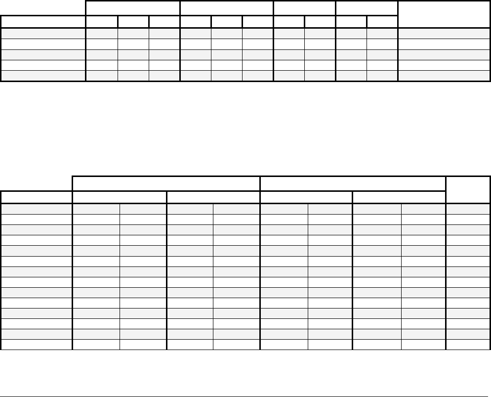
Table 1. Aisle System
AISLE SYSTEM Aisle A Aisle B Aisle C Aisle D
MODE RX A TX A RX C RX B TX B RX D RX C TX C RX D TX D
Auto
Configuration
None Disabled Disabled Disabled Disabled Disabled Disabled Disabled Disabled Disabled Disabled YES
Transceiver Ped Rx Ped Tx N/A Ped Rx Ped Tx N/A Ped Rx Ped Tx Ped Rx Ped Tx YES
Transceiver – Ferrite* Ped Rx Ped Tx Ferrite Ped Rx Ped Tx Ferrite N/A N/A N/A N/A NO
Backfield Ferrite Ped Tx N/A Ferrite Ped Tx N/A Ferrite Ped Tx Ferrite Ped Tx NO
Zone Detect* Ferrite Ped Tx Ferrite Ferrite Ped Tx Ferrite N/A N/A N/A N/A NO
* If Aisle A is in this mode, Aisle C is disabled. If Aisle B is in this mode, Aisle D is disabled.
Table 2. Exit System
Note: Numbers 1, 2, 3, and 4 under mode column indicate the pedestals used. 1-2_3-4 indicates that 1 and 2
pedestals are in one exit, and 3 and 4 pedestals are in another. 1-2-3-4 indicates all pedestals are in one exit.
Note: Disregard receiver settings when using antennas as transceivers.
EXIT SYSTEM Exit 1 Exit 2
MODE PED 1 Connections PED 2 Connections PED 3 Connections PED 4 Connections
Auto
Config.*
None Disabled Disabled Disabled Disabled Disabled Disabled Disabled Disabled NO
1-2_3-4 Dual RX A / Alrm A TX A RX C / Alrm C TX C RX B / Alrm B TX B RX D / Alrm D TX D NO
1-2_3-4 Alternating RX A / Alrm A TX A RX C / Alrm C TX C RX B / Alrm B TX B RX D / Alrm D TX D NO
1-2-3 Split RX A / Alrm A TX A RX C / Alrm C TX C RX B / Alrm B TX B NA NA YES
1-2-3-4 Quad RX A / Alrm A TX A RX C / Alrm C TX C RX B / Alrm B TX B RX D / Alrm D TX D YES
1-2_3-4 Backfield RX A / Alrm A TX A RX C / Alrm C TX C RX B / Alrm B TX B RX D / Alrm D TX D NO
Single Transceiver RX A / Alrm A TX A NA NA NA NA NA NA YES
1_2_3_4 Single** RX A / Alrm A TX A RX C / Alrm C TX C RX B / Alrm B TX B RX D / Alrm D TX D NO
1-2 Dual RX A / Alrm A TX A RX C / Alrm C TX C NA NA NA NA YES
1-2 Dual 3-4 Bfield RX A / Alrm A TX A RX C / Alrm C TX C RX B / Alrm B TX B RX D / Alrm D TX D NO
1-2 Dual 3 Single RX A / Alrm A TX A RX C / Alrm C TX C RX B / Alrm B TX B NA NA NO
1-2 Bfield 3 Single RX A / Alrm A TX A RX C / Alrm C TX C RX B / Alrm B TX B NA NA NO
1-2 Backfield RX A / Alrm A TX A RX C / Alrm C TX C NA NA NA NA NO
1-2 Alternating RX A / Alrm A TX A RX C / Alrm C TX C NA NA NA NA NO
* Only applies to AMS-1100 and AMS-1101 antennas.
** In 1_2_ 3_ 4 Single Mode (where each antenna protects an exit), each antenna alarms independently.

AMS-9050 CONTROLLER 8200-0537-02, REV. B
INSTALLATION AND SERVICE GUIDE 5 of 16
IMPORTANT! DIP S1 and DIP S2 are located on
the circuit board of the controller. When connecting
antennas, set switches 1–8 of each DIP according
to the number and type of antennas used.
Table 1. Rules for using DIP switches
Antenna Controller
Input
DIP S1
DIP S2
AMS-
1100/1101
Transceiver
TXA 1–4 On,
rest don’t care Don’t Care
TXB 5–8 On,
rest don’t care Don’t Care
TXC Don’t Care 1–4 On,
rest don’t care
TXD Don’t Care 5–8 On,
rest don’t care
AMS-1080
Tx/Rx TXA–D 1–8 Off 1–8 Off
Rx Only RXA 1–4 Off,
rest don’t care Don’t Care
RXB 5–8 Off,
rest don’t care Don’t Care
RXC Don’t Care 1–4 Off,
rest don’t care
RXD Don’t Care 5–8 Off,
rest don’t care
Noise Coil 1 RXC
(top coil) Don’t Care 1–2 Off,
rest don’t care
Noise Coil 2 RXD
(top coil) Don’t Care 5–6 Off,
rest don’t care
For example, if using a:
- 1-2 dual pedestal exit system using two
AMS-1101 alarm antennas as transceivers:
- Set S1 switches 1–4 and S2 switches 1–4 to
“on” (switches 5–8 of S1 and S2 can be left
either on or off).
- Also ensure no receive antennas such as
noise coils are connected to the controller
when using transceivers.
- 1-2_3-4 dual pedestal exit system or 1-2-3-4
quad system using four AMS-1101 alarm
antennas as transceivers:
- Set S1 switches 1–8 and S2 switches 1–8 to
“on”.
- Also ensure no receive antennas such as
noise coils are connected to the controller
when using transceivers.
- Dual pedestal aisle system using two AMS-
1080 aisle antennas, one a transmitter, the
other a receiver: Set S1 switches 1–8 and S2
switches 1–8 to “off”.
- Noise coils: If using noise coils, turn off S1
switches 1–2 for RxC and/or S2 switches 5–6
for RxD.
Antenna alarm/Communication connectors
(P92, P93, P97, P100): Four connectors support
the antennas audio/visual alarms, transmitter/
alarms inhibit function, and peripheral RS-485
network communication.
Note: Transmitter/Alarms inhibit function and
peripheral RS-485 network communications are
only available in AMS-1101 antennas.
Receiver Connectors (P98, P99, P101, P103):
Four connectors accept up to four receive
antennas. Top coils use the Coil 1 connections;
bottom coils use the Coil 2 connections.
Noise canceling coils can also share two of these
connectors (P99, P103), with each coil using the
top coil (Coil 1) connection. If connecting a noise
canceling coil and a receive antenna into the same
connector, the top and bottom coils of the receive
antenna must share the Coil 2 connection (done in
the field by the technician switching the antenna
wire connections). Thus phase flipping is
unavailable when noise canceling coils are used.
Antennas/coils connected to receiver inputs are
designated A, B, C, and D. These connectors
default to receive function with no auto detection.
ABOUT NOISE CANCELING COILS: Noise
canceling coils, such as a Ranger antenna or the
top coil of a pedestal antenna, are used to cancel
noise that interferes with detector operation.
- Noise canceling coils only connect to the Coil 1
input.
- To accept a noise canceling coil, the auxiliary
input must be in noise canceling mode (set
using service configurator software). Save
adjustments to default settings if they are to be
used on the next power cycle or system reset.
- Move the noise canceling coil around while
monitoring power levels on a laptop computer to
find where noise cancellation is best. This is
where the coil should be installed.
- The location for the noise canceling coil must be
practical as well as yield satisfactory results.

AMS-9050 CONTROLLER 8200-0537-02, REV. B
INSTALLATION AND SERVICE GUIDE 6 of 16
Relay connectors (P54): The controller has two
double-pole, double-throw (DPDT) relays, each
configurable using service configurator software.
Each relay:
- Triggers devices such as externally powered
remote alarms, time-lapse VCRs, and security
cameras; one device per detection zone.
- Accepts three wires and a shield. Cable shields
share one pin on the connector.
Remote alarm connectors (P63, P64): This
connector can control up to two externally-
powered digital remote alarms, such as an
AMS-1060.
RS-485 network connector (P8): This connector
supports RS-485 communication for remote
diagnostics.
Wired Tx sync connector (P2): This connector is
used to wire two or more AMS-9050 controllers
together to synchronize them to avoid cross
interference.
RS-232 service connection: Protected by a cover
plate on the controller, the RJ-22 connector
receives the cable from a laptop computer that is
used to locally setup and diagnose the detection
system.

AMS-9050 CONTROLLER 8200-0537-02, REV. B
INSTALLATION AND SERVICE GUIDE 7 of 16
Installation Features
The AMS-9050 controller provides the following
installation features:
- Auto Synchronization
- Wired Synchronization
- Transmitter Current Control
- Controller Mounting.
Auto Synchronization
Auto synchronization occurs during power up or
system reset. Auto sync can have different
outcomes depending on whether or not nearby
EAS transmitters are detected, they are properly
aligned to the ac-derived timing of the controller, or
too much ambient noise exists.
No transmitters detected. During initialization, the
controller determines if EAS transmitters are
nearby. If none are found, transmitter delay is set
to zero if this is the initial power on, or set to the
value stored in the controller if not the initial power
on.
Transmitters detected:
- Transmitters detected and aligned. If
transmitters are correctly aligned, the
transmitter delay is calculated and stored in the
controller for reference.
- Transmitters detected and not aligned. If
transmitters are not aligned, the transmitter
delay is set to zero if this is the first power on of
the controller, or set according to the value
stored the controller if not the initial power on.
Too much ambient noise. During initialization, the
controller locates other nearby EAS transmitters.
- If ambient noise prevents the controller from
locating nearby EAS controllers and if this is the
first power on of the controller, transmitter delay
is set to zero.
- If this is not the first power on of the controller,
the zero crossing delay stored in the controller
is used.
Note: The controller stores the zero crossing delay
for when the controller could not determine a
reliable lock during subsequent power cycles.
Instead of using zero for the delay, the controller
uses the stored zero crossing delay.
Wired Synchronization
If a wired Tx sync device is connected to the
controller, the controller automatically uses its
signal as the timing reference instead of the ac
line. The service configurator indicates that wired
sync is active.
Transmitter Current Control
This function enables you to inhibit the transmitter
and/or alarms of the desired pedestal using the
Tx/Alarms inhibit switch located in the top of
antennas that support this function.
Controller Mounting
The controller has a built-in flange used to attach
the controller to a wall or ceiling using suitable
hardware.
- Ceiling attachment requires plywood be first
attached to the ceiling and then the controller
attached to the plywood.
- Structure and mounting hardware must support
25.6kg (56.5 lbs) or four times the weight of the
controller assembly.

AMS-9050 CONTROLLER 8200-0537-02, REV. B
INSTALLATION AND SERVICE GUIDE 8 of 16
Service Features
The AMS-9050 controller provides the following
service features:
- “Tag Too Close” function
- Service configurator software
- Internal diagnostics
- LED system status indicator
- Remote diagnostics via an Ethernet or RS-485
network
- Transmit/Alarm Inhibit function
- Detachable cable access panel.
“Tag Too Close” function: Using the service
configurator, you can select the “tag-too-close”
function to help prevent false alarms. With this
function selected, the red lamp on top of the
antenna blinks twice every four seconds for one
minute when the system detects one or more
stationary tags or labels are too close to it. The
lamp goes out when these tags/labels are moved
away from the system.
Tagged items must be kept at least 1.5m (5ft) away
from all sides of the antenna.
Service configurator software: Operating
software required: Windows® 95, 98, NT, 2000, or
XP.
Service configurator software downloaded to a
laptop computer is required to setup and
troubleshoot the controller. The service
configurator enables you to:
- Set antenna configurations
- Customize detection for each antenna
- Monitor transmit and noise levels from each
antenna
- Monitor transmit current from each antenna
- Customize alarm setup
- Turn off transmitters
- Monitor temperature inside the controller
- Download new software features/updates to
flash memory
- Provide a system error report.
Note: Special tools are not required when installing
the controller as long as the antennas are installed
in a reasonable noise environment and local
transmitters are properly adjusted.
Note: If default settings are changed, you do not
need to turn the controller off and on to store them.
Internal diagnostics:
- The service configurator displays the operating
current for each antenna. Operating current is
15A peak for all countries.
- The service configurator displays ambient
temperature within the controller.
- The hardware supports software with a remote
command to reset the system.
- Hardware within the controller protects it from
runaway software.
LED system status indicator: An LED system
status indicator on the controller indicates the
following:
- Green flashing (system on and okay)
- Yellow flashing (performance downgraded;
service recommended)
- Red flashing in a particular sequence (fault
detected, call for service)
The number of red flashes identifies a digit in a
two-digit alert code (for example, four flashes is
the number four). The start of an alert code is
indicated by a long LED interval. Then the first
digit of the code occurs, followed by a short
delay, followed by the second digit.
Alert codes are listed on page 13.
Remote diagnostics via an Ethernet or RS-485
network: Using a service laptop, service personnel
can dial-up and connect to a network of controllers
to troubleshoot problems and change controller
parameters (see page 14).
Transmit/Alarm Inhibit function: This function
enables you to inhibit the transmitter and/or alarms
of the desired pedestal using the Tx/Alarms inhibit
switch located in the top of antennas supporting
this function.
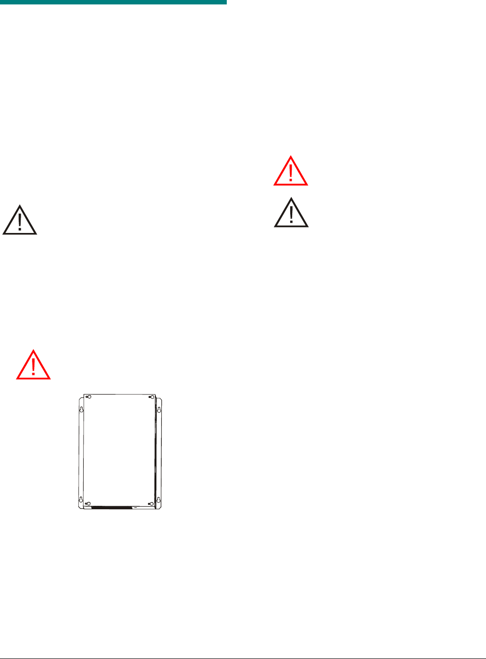
Detachable cable access panel: By removing six
screws from the perimeter of the cable access
panel and disconnecting cables, the electronics
can be removed for easy servicing or replacement
without disturbing cabling.
AMS-9050 CONTROLLER 8200-0537-02, REV. B
INSTALLATION AND SERVICE GUIDE 9 of 16
Installation Requirements
Verifying Equipment and Unpacking
- Verify that all equipment has arrived. Ensure the
system configuration is correct for the site.
- Unpack major components in a back room. At
the install site, lay out parts in the order used.
Do not clutter the aisle or cause a trip hazard.
Installer/Contractor
- Have electrical work comply with the latest
national electrical code, national fire code, and
all applicable local codes and ordinances.
- Coordinate work with other trades to avoid
interference.
- Verify existing site conditions and coordinate
with the owner’s representative and appropriate
utilities as required.
- Obtain copies of all related plans, specifications,
shop drawings and addenda to schedule and
coordinate related work.
- Thoroughly review the project to ensure that all
work meets or exceeds the above requirements.
Bring alleged discrepancies to the attention of
Sensormatic Electronics.
Mounting Requirements
- The controller has a built-in flange used to
attach the controller to a wall or ceiling using
suitable hardware. Structure and hardware must
support 25.6kg (56.4 lbs) or four times the
weight of the controller assembly.
- Do not mount controller with its fan facing up.
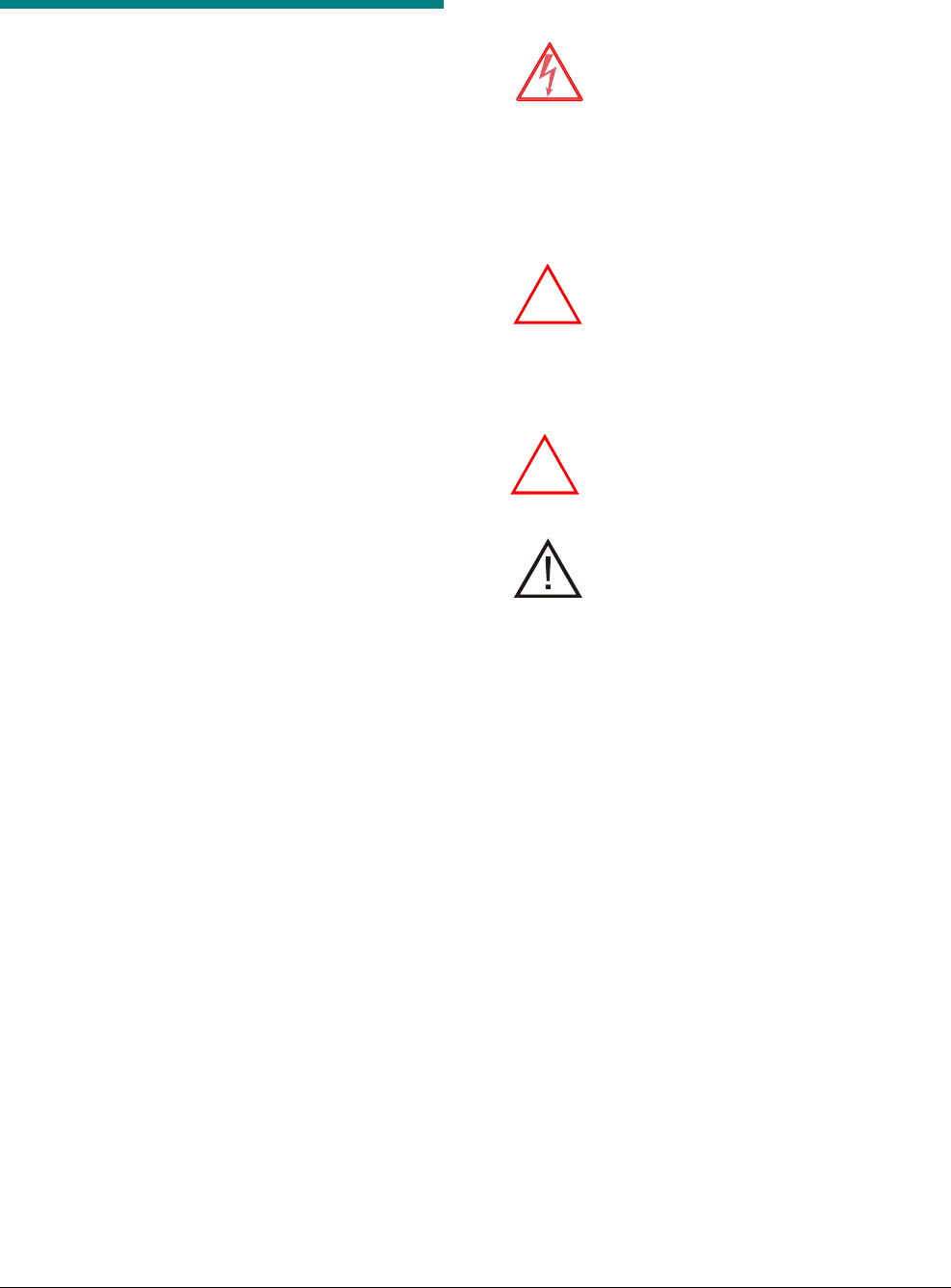
AC Requirements
WARNING—RISK OF ELECTRIC
SHOCK! During installation, if the
antenna must be left unattended, turn off
power or cover high voltage components
to prevent unauthorized access to
hazardous voltages.
WARNING—RISK OF ELECTRIC
SHOCK! The ac power cord could be
carrying 120Vac or 240Vac.
WARNING! Do not install this device
where highly combustible or explosive
products are stored or used.
WARNING! The ac source must be a 2-
wire type with ground. It also must be a
24-hour, unswitched outlet with less than
0.5Vac between neutral and ground.
WARNING! This device is not suitable
for an IT power distribution system
where impedance exists between neutral
and protective earth contacts.
CAUTION: When using a power cord,
install a socket-outlet near the controller
in an easily accessible location. The
appliance coupler or plug on the power
supply cord are the specified disconnect
devices.
CAUTION: DO NOT share the ac source
with neon signs, motors, computers,
cash registers, terminals, or data
communications equipment.
CAUTION: DO NOT use orange-colored
outlets dedicated for computer
equipment.
CAUTION: Select the appropriate power
cord based on the country of use.
!
!

AMS-9050 CONTROLLER 8200-0537-02, REV. B
INSTALLATION AND SERVICE GUIDE 10 of 16
Mounting the Controller
WARNING! Do not mount controller with
its fan or cable tray face up.
The controller can be mounted as follows:
- On a shelf.
- On a wall. DO NOT mount the controller with its
fan facing up!
- To a ceiling. Plywood with a surface larger than
the controller is secured to the ceiling studs that
hold the drywall. The controller then attaches
with suitable hardware to the plywood.
Equipment Required
Basic setup requires the following equipment:
• AMS-9050 controller
• Pedestal antennas
• Hard tag (non-deactivateable Ultra•Max tag)
• Ultra•Max low energy labels.
Advanced setup requires the following additional
equipment:
• Laptop with Windows® 95, 98, NT, 2000, or XP
operating software
• RS-232 Ultra•Max programming cable
• ADS 4 service configurator software.
People with Implanted Medical Devices
Although this anti-theft system meets standards for
interaction with implanted medical devices, place
the system in such a way that customers:
- do not linger near or lean on its antenna(s)
while making their purchase
- are only directly in front of the antenna(s) while
exiting the checkout area.
!
!
AMS-9050 CONTROLLER 8200-0537-02, REV. B
INSTALLATION AND SERVICE GUIDE 11 of 16
Controller Installation
Tools required:
- Tape measure
- Pencil or marker
- Electric drill
- Phillips-head screwdriver or bit
- Hand vacuum or broom
Parts required:
Install Kit 0352-0203-01
Screw, self-drilling, M4, 8x25, PHP 4 5899-0031-01
Install Kit 0352-0286-01
Clamp, conduit 6 6010-0107-01
PROCEDURE
CAUTION: Keep 22.9cm (9in) of free
space to the right of the controller for
screwdriver access (to facilitate
detachment of controller electronics).
1. Detach the top cover from the controller.
2. Remove knockouts closest to the connectors to
be used, then reattach the side plate.
3. Set the controller on a shelf, or using suitable
anchors and hardware, mount it to a wall (fan
facing down) or to a ceiling.
WARNING! Both the anchor system
and the wall or ceiling must be able to
support 25.6kg (56.4 lbs).
4. Run cables through the appropriate knockouts
and secure them using cable clamps provided.
AC Hookup
1. Choose a power cord for the country of use.
USA-IEC 320, 18/3, 125V, 10A, 7.5ft. 0351-0547-01
Schuko-IEC 320, 1mm sq., 250V, 10A, 2.5m 0351-0547-02
UK-IEC 320, 1mm sq., 250V, 10A, 2.5m 0351-0547-03
Japan-IEC 320, 2mm sq., 250V, 15A, 2.5m 0351-0547-04
US-Filter, Line, 125V, 6A, Plug-in 0351-0547-05
Australia to IEC 320, 2.5m, 250V, 10A 0351-0547-07
2. Plug in the power cord. The controller
automatically senses the voltage (100-120Vac
or 200-240Vac). No adjustments are required.
WARNING—RISK OF ELECTRIC
SHOCK! The ac power cord may carry
120Vac or 240Vac.
CAUTION: When using a power cord,
a socket-outlet must be installed near
the controller and in an easily
accessible location.

AMS-9050 CONTROLLER 8200-0537-02, REV. B
INSTALLATION AND SERVICE GUIDE 12 of 16
System Setup
1. Ensure controller power is off.
2. Connect antenna cables to the controller
according to how the antennas are intended to
perform. Refer to diagrams and tables on pages
3 and 4 of this guide. See examples of pedestal
installations in the antenna installation guide.
3. Set DIP switches S1 and S2 in the controller for
the pedestal type, number of pedestals, and the
antenna configuration used (see page 5).
4. Turn on the laptop computer and launch the
ADS 4 service configurator.
Note: For instructions on how to use configurator
settings, click Help on the configurator.
IMPORTANT! Ensure the controller power is off.
Never restart or boot up a computer connected to
an active controller. Doing so disables the mouse
function on the computer.
5. Turn on the controller and connect the laptop
computer to the service port.
6. Using the “Setup” page on the configurator:
a. Check that antenna selections match
antennas physically installed. If not, check
antenna connections to the controller.
b. Setup parameters for lamps, audio, relays,
and remote alarms.
7. Using the “Tx Configuration” page, set Tx
current for each antenna and enable/disable
transmitters, if necessary.
8. Pass an active security tag by each antenna to
verify antenna performance. Refer to Help if
monitoring or adjustments are necessary.
Verifying Operation
Check that the antenna alarm lamp lights when a
tag/label is passed through the checkout aisle, or if
the system is covering adjacent aisles, that the
lamp lights only in the aisle the tag/label was in.
If the pick rate is acceptable, installation is
complete. Reattach the top cover.

AMS-9050 CONTROLLER 8200-0537-02, REV. B
INSTALLATION AND SERVICE GUIDE 13 of 16
Troubleshooting
Note: Should the electronics require servicing or
replacement, detach the electronics from the cable
access panel as follows:
1. Loosen the four top screws and detach the
cover from the controller.
2. Unplug all cable connectors and the ac power
cord.
3. Remove six screws securing the cable access
panel to the controller.
4. On the left side of the controller, loosen the two
screws holding the controller to the wall.
5. Lift the electronics enclosure up and off the wall.
System Status Alert Codes
The System Status LED on the controller displays
system status alert codes. When an alert code
occurs, the LED changes color and pattern. Red is
for serious alerts while yellow is for those less
serious.
a. The number of red flashes identifies a digit in a
two-digit alert code (for example, four flashes is
the number four). The start of an alert code is
indicated by a long LED interval. Then the first
digit of a two-digit error code occurs, followed by
a short delay, followed by the second digit.
b. See the table opposite for the significance of the
alert code. Most alert codes are automatically
resolved.
c. Some codes can only be accessed using the
service configurator. They are not displayed by
the Status LED.
d. Alert codes are lost when the controller is reset.
Code storage has a time stamp in days, hours,
minutes, seconds, milliseconds/ ticks of when
the system alert occurred.
The following critical faults are backed with
hardware support and provide the necessary action
when encountered.
- Current fault 1 per channel
- Temperature fault
- Primary current fault
- Secondary current fault
- Last resort current fault to maintain Class 2
wiring requirements.
Alert codes repeat until the condition is resolved or
a timer resets the system.
Alert Codes
Alert Code Significance
11 Illegal Instruction Return controller
12 Unimplemented Interrupt Return controller
13 NVM Write Failed Return controller
14 Invalid Device Return controller
15 Sequence Table Error Return controller
16 Out of Memory Return controller
17 Undecided: No Split N/A
18 Watchdog: Task Reset Return controller
21 AntA S/W Current Fault Recoverable
22 AntB S/W Current Fault Recoverable
23 AntC S/W Current Fault Recoverable
24 AntD S/W Current Fault Recoverable
25 H/W Current Fault Recoverable
26 AntA Current Sense Fault Recoverable
27 AntB Current Sense Fault Recoverable
28 AntC Current Sense Fault Recoverable
29 AntD Current Sense Fault Recoverable
39 Sequence Table Mismatch Recoverable
41 Missing Zero Crossing Return controller
42 Wired Sync: Missing Signal Recoverable
43 Temperature Fault Recoverable
44 S/W Temperature Fault Recoverable
45 PWM Fault Return controller
46 Fan Fault Recoverable
49 Realtime Error Return controller
51 Autosetup Owner Timeout Recoverable
52 Autosetup Release W/O Lock Recoverable
53 Autosetup Buffer Overrun Recoverable
54 Autosetup Mailbox Full Recoverable
56 Notch Select Timeout Recoverable
57 Window Select Timeout Recoverable
58 Autosetup Illegal Owner Recoverable
61 Detector Overrun Recoverable
62 Alarm Mailbox Full Recoverable
63 Host Comm Mailbox Full Recoverable
64 Host Comm Mailbox Full Recoverable
71 Host Comm Mailbox Full Recoverable
AMS-9050 CONTROLLER 8200-0537-02, REV. B
INSTALLATION AND SERVICE GUIDE 14 of 16
Local Diagnostics
The AMS-9050 controller enables you to
troubleshoot and change controller parameters
using your laptop computer and the ADS 4 service
configurator.
The following hardware is required:
• Laptop computer
• Service cable with a male RJ-10/22 phone connector
on one end and a male RJ-11/12 connector on the
other
• DB-9-to-RJ-11/12 connector.
How to Connect Cables
1. Connect the DB-9-to-RJ-11/12 connector to
the DB-9 serial port on your laptop computer.
Only pins 2, 3, and 5 are used.
2. Connect the RJ-11/12 connector of the service
cable to the DB-9 connector and the RJ-10/22
connector on its other end to the RS-232 port
(RJ-10/22) on the controller.
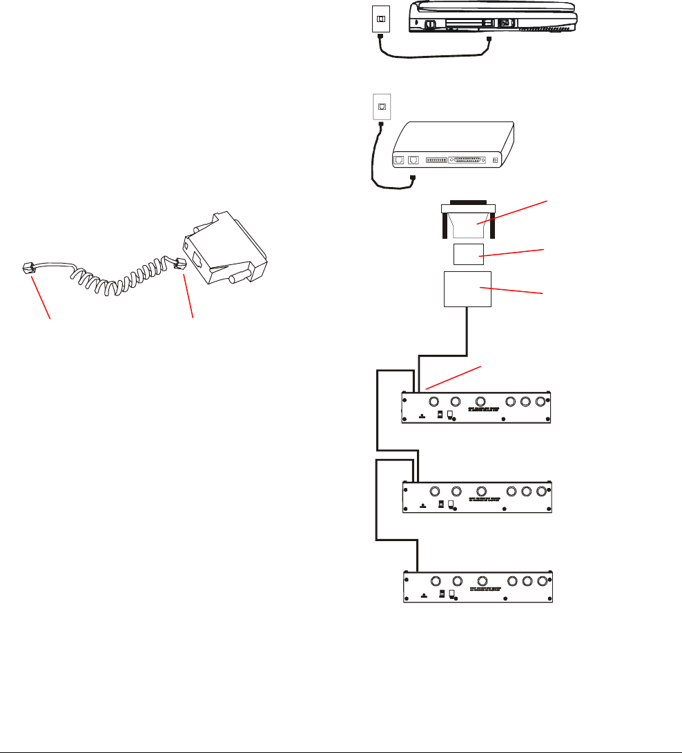
Remote Diagnostics
The AMS-9050 controller enables you to use an
RS-485 network to troubleshoot and change
controller parameters from a remote site. To
connect to the network, connect the laptop, modem
and accessories as shown below. The cables
connect to the RS-485 connector inside the
controller using a T adapter.
DB-9
RJ-11/12
RJ-10/22 to
RS-232 port on
controller
DB-25 male to DB-9
male adapter
Null modem adapter
Modem
RS-232/RS-485
converter
Controller RS-485 port
(inside controller)
Laptop
AMS-9050 CONTROLLER 8200-0537-02, REV. B
INSTALLATION AND SERVICE GUIDE 15 of 16
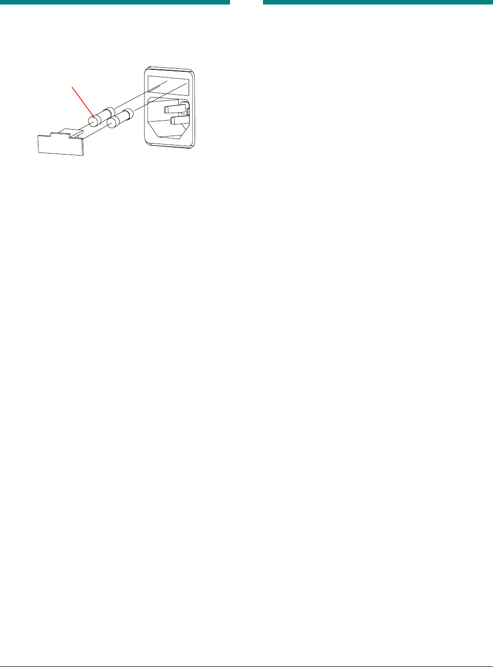
Fuse Replacement
The controller has two 2.5A, 250V slow-blow fuses
in the IE320 ac receptacle.
1. Pry the rectangular cover plate from the ac
receptacle using a small slotted screwdriver.
Two spring-loaded fuses should pop out.
2. Replace the blown fuse (or fuses) with 2.5A,
250V slow-blow fuses (P/N 5111-0028-08).
Specifications
Electrical
POWER SUPPLY
Primary input............................ 100-120Vac or
200-240Vac @ 50–60Hz
Primary power fuse .................. 2.5A, 250V, slo-blow,
hi-breaking
Current draw (120V)................. <1.5Arms
Current draw (240V)................. <1Arms
Input power (120V)................... <130W
Input power (240V)................... <123W
TRANSMITTER
Operating frequency................. 58kHz (±200Hz)
Transmit burst duration ............ 1.6ms
Transmit current maximum ...... 15A peak
Burst Repetition Rate:
Based on 50Hz ac.................... 75Hz or 37.5Hz
Based on 60Hz ac.................... 90Hz or 45Hz
RECEIVER
Center frequency...................... 58kHz
Environmental
Ambient temperature................ 0°C to 50°C
(32°F to 122°F)
Relative humidity...................... 0 to 90%
non-condensing
Mechanical
Length...................................... 44.6cm (17.6in)
Width........................................ 33.5cm (13.2in)
Height....................................... 9.2cm (3.6in)
Weight...................................... 6.4kg (14.1 lbs)
Fuses (2)

AMS-9050 CONTROLLER 8200-0537-02, REV. B
INSTALLATION AND SERVICE GUIDE 16 of 16
Declarations
TYPE: AMS-9050
Regulatory Compliance
EMC...............................47 CFR, Part 15
EN 61000-3-2
EN 61000-3-3
ETSI EN 300 330-2
ETSI EN 301 489-3
ETSI EN 301 489-1
RSS-310
Safety ............................UL 60950-1
CSA C22.2 No 60950-1
EN 60950-1
FCC COMPLIANCE: This equipment complies
with Part 15 of the FCC rules for intentional
radiators and Class A digital devices when installed
and used in accordance with the instruction
manual. Following these rules provides reasonable
protection against harmful interference from
equipment operated in a commercial area. This
equipment should not be installed in a residential
area as it can radiate radio frequency energy that
could interfere with radio communications, a
situation the user would have to fix at their own
expense.
EQUIPMENT MODIFICATION CAUTION:
Equipment changes or modifications not expressly
approved by Sensormatic Electronics Corporation,
the party responsible for FCC compliance, could
void the user's authority to operate the equipment
and could create a hazardous condition.
Other Declarations
WARRANTY DISCLAIMER: Sensormatic
Electronics Corporation makes no representation
or warranty with respect to the contents hereof and
specifically disclaims any implied warranties of
merchantability or fitness for any particular
purpose. Further, Sensormatic Electronics
Corporation reserves the right to revise this
publication and make changes from time to time in
the content hereof without obligation of
Sensormatic Electronics Corporation to notify any
person of such revision or changes.
LIMITED RIGHTS NOTICE: For units of the
Department of Defense, all documentation and
manuals were developed at private expense and
no part of it was developed using Government
Funds. The restrictions governing the use and
disclosure of technical data marked with this
legend are set forth in the definition of “limited
rights” in paragraph (a) (15) of the clause of
DFARS 252.227.7013. Unpublished - rights
reserved under the Copyright Laws of the United
States.
TRADEMARK NOTICE: Sensormatic is a
registered trademark of Sensormatic Electronics
Corporation. Other product names mentioned
herein may be trademarks or registered
trademarks of Sensormatic or other companies.
No part of this guide may be reproduced in any
form without written permission from Sensormatic
Electronics Corporation.
MDR 1/2006