Tyco Safety Sensormatic AMS90604 Anti-pilferage Device User Manual
Tyco Safety Products/Sensormatic Anti-pilferage Device Users Manual
UserManual.wiki
>
Tyco Safety Sensormatic
>
AMS90604 User Manual
Users Manual
Navigation menu
Upload a User Manual
Namespaces
Wiki Guide
HTML
PDF
Info
Views
User Manual
Discussion / Help
Navigation

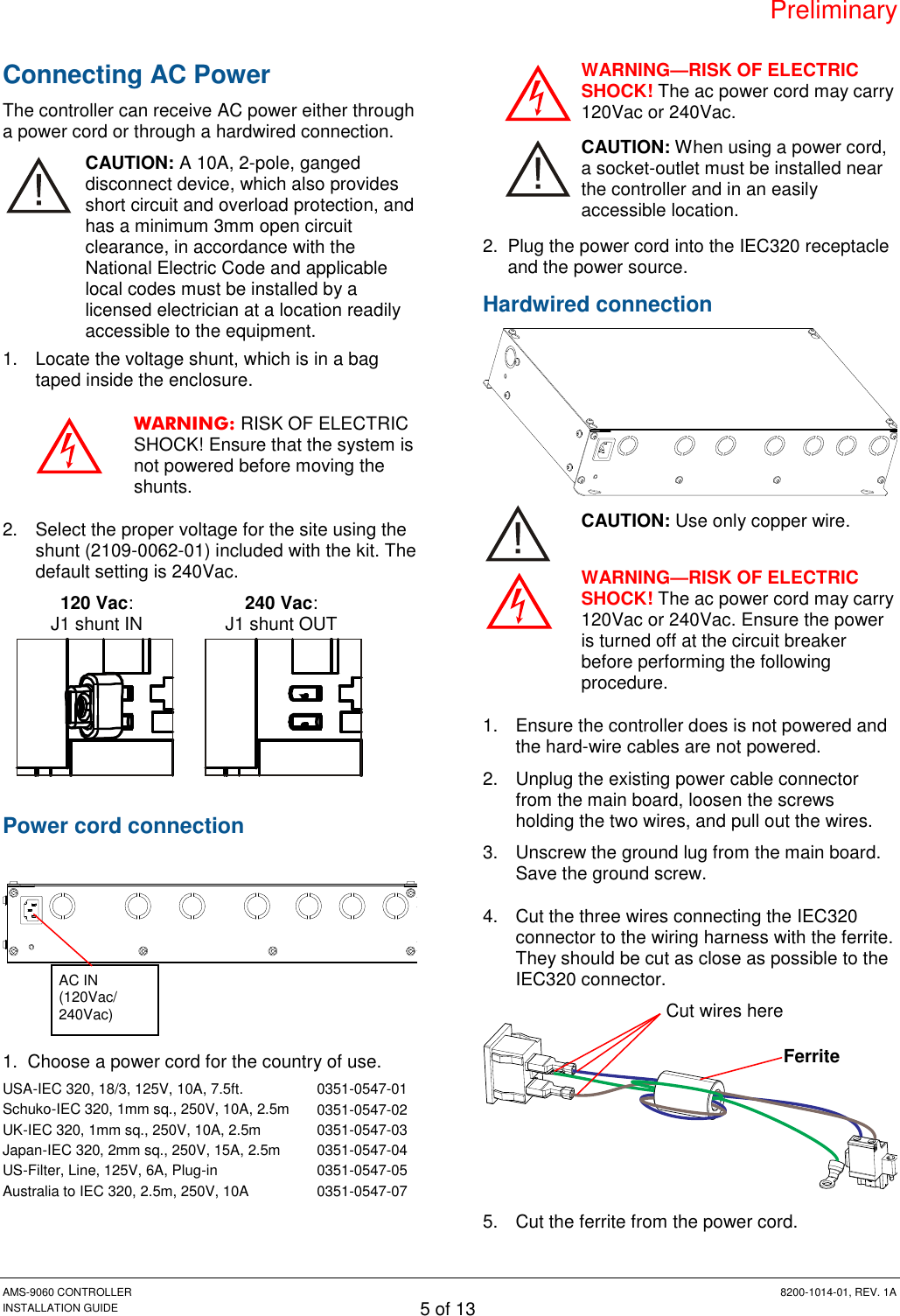
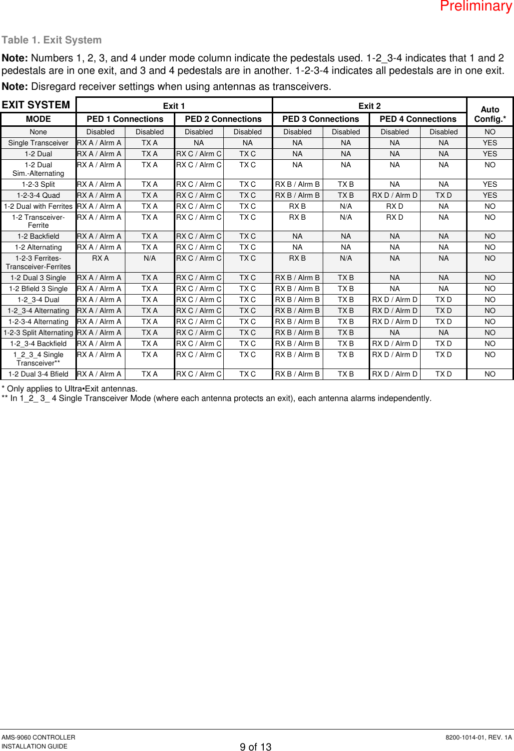
![Preliminary AMS-9060 CONTROLLER 8200-1014-01, REV. 1A INSTALLATION GUIDE 8 of 13 Figure 1. AMS-9060 connectors (with pinouts), jumpers, and switches P3 P4 P5 P17 J2 P18 J3P32P30P31P28P26P25P24P23P22P21P20P19P11 2J1S1S2S31 1 88 OffOnOffOn1 2 3 4 5 1 2 3 4 5 1 2 3 4 5 1 2 3 4 5 1 2 3 4 51 2 31 2 31 2 31234 5 1 2 3 4 5 1 2 3 4 5 1 2 3 4 5 1 2 3 4 5BKRD O GNWT BKRD O GNWTBKRD O GNWTBKRD O GNWTP32 (NET RS485) Pin 3 – (Shield) Pin 2 – (Network RS485 HI) Pin 1 – (Network RS485 LO) P18 (WIRED SYNC) Pin 1 – Black (Tx Burst High) Pin 2 – Red (Tx Burst Low) Pin 3 – Green (Arm High) Pin 4 – White (Arm Low) Pin 5 – (Shield) P30, P31 (REM ALARM 1 and 2) Pin 3 – (Shield) Pin 2 – (Peripheral RS485 HI) Pin 1 – (Peripheral RS485 LO) J2 (RELAY A-B) Pin 8 – NC 1 Pin 7 – Common 1 Pin 6 – NO 1 Pin 5 – NC 2 Pin 4 – Common 2 Pin 3 – NO 2 Pin 2 – Ground Pin 1 – Ground P3, P4, P5, P17 (RX1-4) Pin 1 – Black (Antenna [A-D]1) Pin 2 – Red (Antenna [A-D]1 return) Pin 3 – Green (Antenna [A-D]2) Pin 4 – Gray/White (Antenna [A-D]2 return) Pin 5 – Violet / ‘X’ (Shield) Note: Color may vary depending on device. P19, P21, P23, P25 (PED A-D Tx/Rx) Pin 1 – Black (Bottom coil return) Pin 2 – Red (Bottom coil) Pin 3 – (Shield) Pin 4 – Green (Top coil return) Pin 5 – White (Top coil) P20, P22, P24, P26 (COMM A-D) Pro•Max 5 Pin 1 – (Shield) Pin 2 – Black (Ground) Pin 3 – Orange (12V) Pin 4 – Brown (Peripheral RS485 LO) Pin 5 – Red (Peripheral RS485 HI) Ultra•Exit (AMS-9060 compatible) Pin 1 – (Shield) Pin 2 – No connect (Ground) Pin 3 – Brown (12V) Pin 4 – Black (Peripheral RS485 LO) Pin 5 – Red (Peripheral RS485 HI) P28 (EXT. TX INHIBIT) Pin 1 – (Tx Inhibit 1) Pin 2 – (Ground) Pin 3 – (Tx Inhibit 2) Pin 4 – (Ground) Pin 5 – (Tx Inhibit 3) P1 (AC) Pin 1 – L1/PRI Pin 2 – L2/NEU J3 (RS232) Pin 1 – (RxD) Pin 2 – (TxD) Pin 3 – (Ground) Pin 4 – (No Connect) S1 A/B DIP Switches Pins 1-4 – Ped A Pins 5-8 – Ped B On – Port is Tx/Rx Off – Port is Tx only, Rx is at Rx port S3 (Flash Override Pushbutton) DS1 (Power LED) F1 (Fuse L1 ) F2 (Fuse L2 ) J1 (120V/240V) 120V - In 240V - Out S2 C/D DIP Switches Pins 1-4 – Ped C Pins 5-8 – Ped D On – Port is Tx/Rx Off – Port is Tx only, Rx is at Rx port Reserved (P2) Reserved (P16) Grounding Screw](https://usermanual.wiki/Tyco-Safety-Sensormatic/AMS90604/User-Guide-2273430-Page-8.png)