Tyco Safety Sensormatic AMX1000 Ultra Max Phasing Tool User Manual 8k257449 1bx
Tyco Safety Products/Sensormatic Ultra Max Phasing Tool 8k257449 1bx
User Manual
Preliminary
ULTRA MAX PHASING TOOL 8000-2579-49 REV. B
USER GUIDE
1 of 9
8000-2579-49
Ultra Max
®
Phasing Tool
User Guide
AMX-1000
If you need assistance...
Contact your Technical Support.
About this guide
This guide provides you with information on how to
use the Phasing Tool. This tool eliminates the need
to use an oscilloscope when wirelessly phasing
and synchronizing systems.
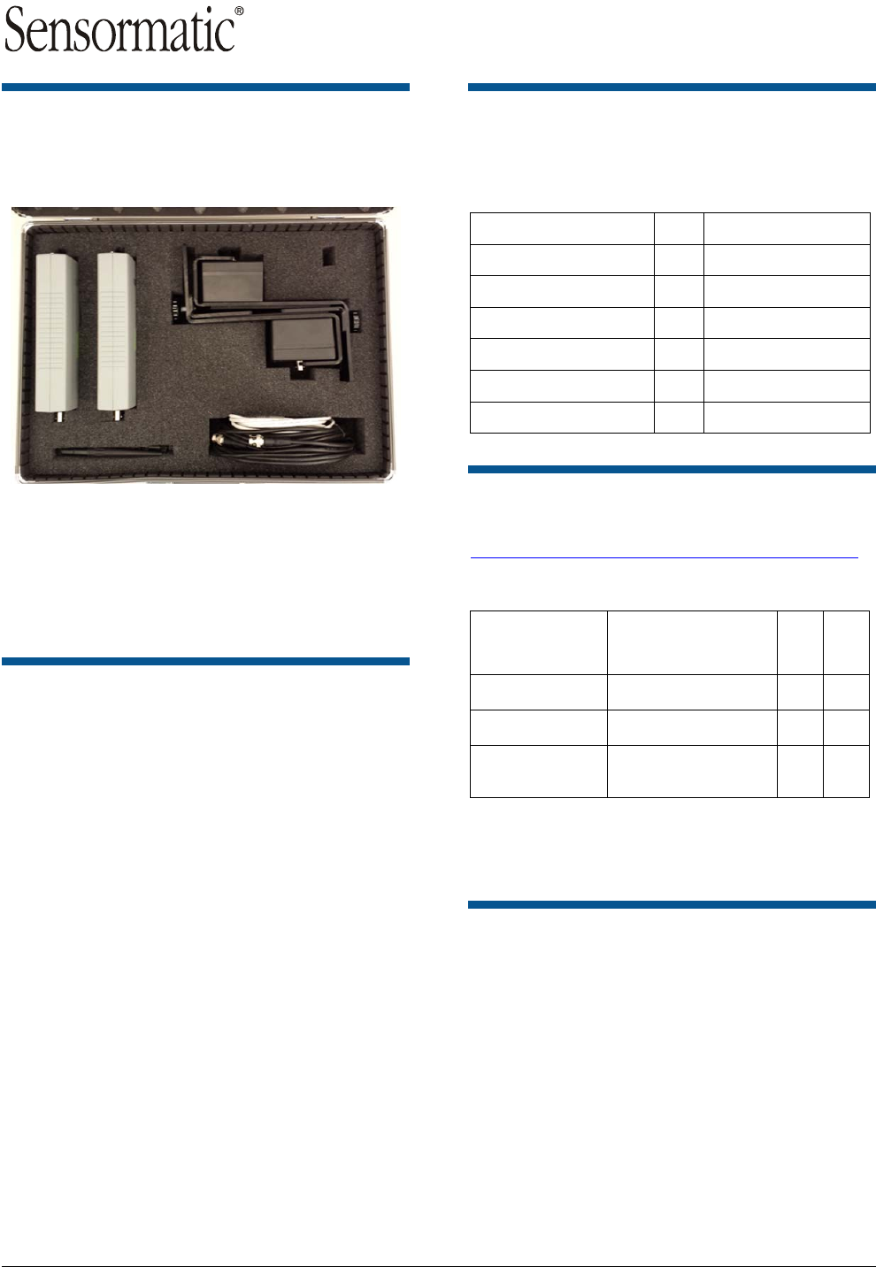
About the product
Part numbers
Table 1. AMX-1000 Phasing tool kit with case
Item Qty Part Number
Phasing Tool 2 0304-0152-01
Brackets for Sense Coil 2 0400-1182-01
Sense Coils 2 0300-2274-01
Cable RG58A 12ft 1 6003-0313-01
Cable USB A/Micro B 6ft 1 6003-0148-01
A
ntenna 2.4GHz 2 3411-0024-01
Spare parts
A complete parts list is available online at:
http://www.sensormatic.com/support/techsupport/.
Login, and then click the Part Information link on
the Tech Support home page.
Part Number /
Product Code Description
9U*
FRU**
0352-0706-01 3dB Transceiver Antenna No Yes
0352-0707-01 Pickup Coil and Bracket No Yes
0352-0708-01 Phasing Tool Transceiver
Module No Yes*
* Repairable unit
** Field replaceable unit.
*** Outside North America only.
Key features
Two identical phase modules are used. One is set
as a transmitter and the other is set as a receiver.
Both the receiver and transmitter are battery
operated. When the unit is connected to the laptop
via USB cable it switches to USB power.
The sense coils pick up a 58kHz signal from the
antenna. An application on the laptop shows the
phase delta between the systems. No oscilloscope
is required to complete phasing.
© 2016 Sensormatic Electronics, LLC
Preliminary
ULTRA MAX PHASING TOOL 8000-2579-49 REV. B
USER GUIDE
2 of 9
8000-2579-49
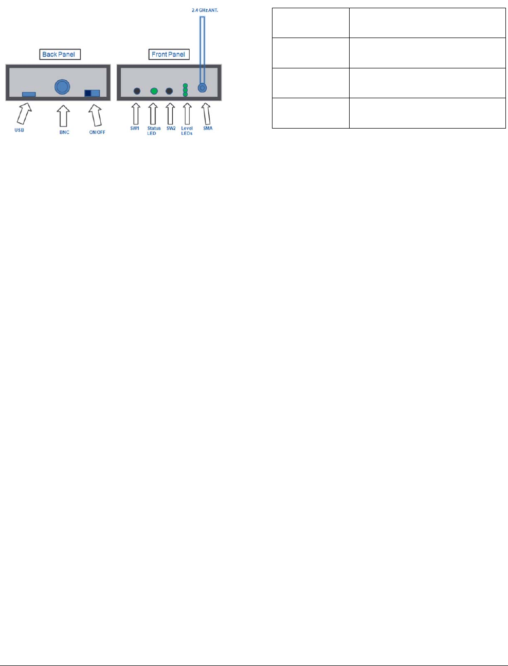
Front Panel functions
RSSI Signal Strength Reading
Press and release SW2 once. This shows the
strength of the RSSI signal on the level LEDs, with
LED 1 indicating the weakest and LED 3 indicating
the strongest 2.4GHz RSSI signal strength.
Battery Level Indication
Press and release SW2 twice in succession. This
displays the battery level on the three level LEDs,
with 1 indicating a low battery level, 2 indicating a
medium battery level, and 3 indicating a high
battery level.
58KHz Signal Lock Status
No button press required. The status LED flashes
red with no 58 KHz present, and flashes green at a
rate of approximately once per second as soon as
a 58 KHz signal lock is achieved.
Setting the unit as transmitter or receiver
Pressing and holding down SW1 displays the
current configuration. Pressing and holding down
SW1, while pressing and releasing SW2, one time,
toggles the unit between transmitter and receiver
mode. The setting is indicated by the 3 level LEDs.
The level LED 1 indicates the receiver function,
while the level LED 3 indicates a transmitter.
Power Save Mode
The phasing tool goes into power save mode to
preserve the battery when no 58 kHz signal is
detected for five consecutive seconds. All LEDs
turn off when it enters power save mode. The
phasing tool wakes up from power save mode
once a 58 kHz signal is detected. The mode is
disabled when the USB cable is connected
between the phasing tool and the computer.
System Synchronization Test Function
When the phasing tool is set to receiver mode, and
has a signal lock on the 58 kHz of a system whose
phase is being checked, it indicates the phase
relationship to the reference system on the level
LED’s. The LEDs flash as follows:
LED Number Phase Indication Relative to
Reference
LED #1 System Phase is Lagging by more
than 50 µsec
LED #2 System Phase is Between plus or
minus 50 µsec
LED #3 System Phase is Leading by more
than 50 µsec
Note: 1 millisecond (msec or ms) = 1000
microseconds (µsec or µs).
To convert to milliseconds, divide microseconds by
1000.A shortcut is to shift the decimal point to the
left three places, which is the same as dividing by
1000.
0.050. (µs) = 0.05 (ms)
For example, 50µs = 0.0
5ms, 100µs = 0.1ms
58kHz Field Strength Mode
When the phasing tool is set to receiver mode, and
a laptop computer is connected the 58 kHz field
strength quality can be seen by typing “2” in the
command line of the laptop console window. This
starts the “PLL summary print” function that
continuously prints to the screen the lock or unlock
state of the phase lock loop and a relative signal
strength quality rating system represented by
groups of stars.
The displayed signal strength is based on the level
of the previous reading. Moving from a weaker field
to a stronger field results in an increase in the star
rating, and moving from a stronger field to a
weaker field would result in a decrease in the star
rating.
***|***|***|***: Very Strong
***|***|***|000: Strong
***|***|000|000: Moderate
***|000|000|000: Weakest
The field strength quality can be useful to locate
the point where the field is the strongest on
concealed antennas systems or some deactivators.
Below is an example of the PLL summary print
showing the PLL is “Locked” and a field strength
quality of “3”:
Preliminary
ULTRA MAX PHASING TOOL 8000-2579-49 REV. B
USER GUIDE
3 of 9
8000-2579-49
***|***|***|000:-10: LOCKED: (-77:54:131)!99-5556
Strength= 3 PLL
The “2” command is a toggle. Typing “2” again
turns the mode off.
Enable Boot Loader Mode
Ensure the power switch is off. Press and hold
SW1 and SW2 simultaneously while sliding the
power switch to the ON position. Continue pressing
SW1 and SW2 until all 3 level LEDs are flashing.
At this point SW1 and SW2 may be released. The
unit is now ready to receive a flash download via
USB.
Phasing Tool Transmitter
Setup
At the reference system location:
1. Attach one of the 2.4GHz SMA antennas to the
SMA connector on the phase tool.
2. Slide the power switch to the on position.
3. To set this unit as a transmitter, hold down
SW1 while pressing and releasing SW2. This
toggles the unit between transmitter and
receiver mode.
LED 1 indicates receiver
LED 3 indicates transmitter
4. Attach the coaxial cable to one of the sense
coils.
5. Hang the sense coil using the hanging bracket
on the reference system antenna.
Important: Move the bracket along the top of
the antenna until it locks. The location for the
coil varies on the different antennas.
6. Attach the other end of the coaxial cable from
the sense coil to the BNC connector on the
phasing tool.
Note: The status LED initially blinks red. When
it has locked onto the 58 kHz signal from the
pedestal the status LED blinks green.
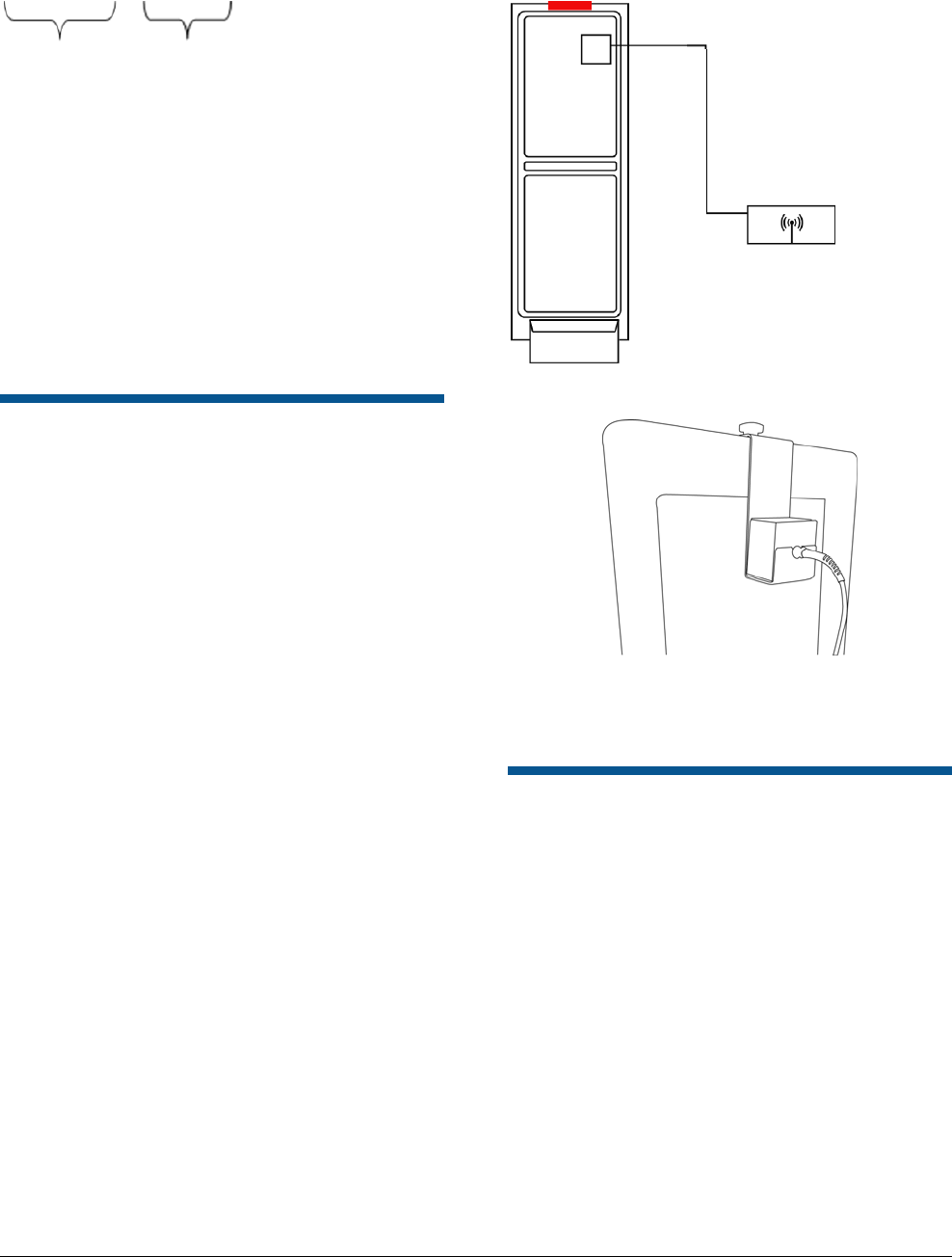
Figure 1.Primary Transmitter Setup
Figure 2. Pickup Coil on Bracket
Note: Move the coil along the antenna until the
phasing locks to the signal.
The location varies on the different antennas.
Phasing Tool Receiver Setup
1. Repeat Steps 1-4 from the Phasing Tool
Transmitter Setup section and set the unit to
receiver.
2. Hang the sense coil using the hanging bracket
on the antenna of the system to be phased. .
3. Attach the other end of the coax cable from the
sense coil to the BNC connector on the phase
tools.
Note: The status LED initially blinks RED, and
once it has achieved a lock on the 58 KHz
signal from the pedestal, the status LED starts
blinking GREEN
4. Observe the Level LEDs to determine the
system phase
If LED 1 is lit system being checked is
lagging greater than 50usec
Phasing tool
Coaxial Cable
Preliminary
ULTRA MAX PHASING TOOL 8000-2579-49 REV. B
USER GUIDE
4 of 9
8000-2579-49
If LED 2 is lit system being checked is
within the +/- 50usec window considered to
be in-phase
If LED 3 is lit system being checked is
leading greater than 50usec
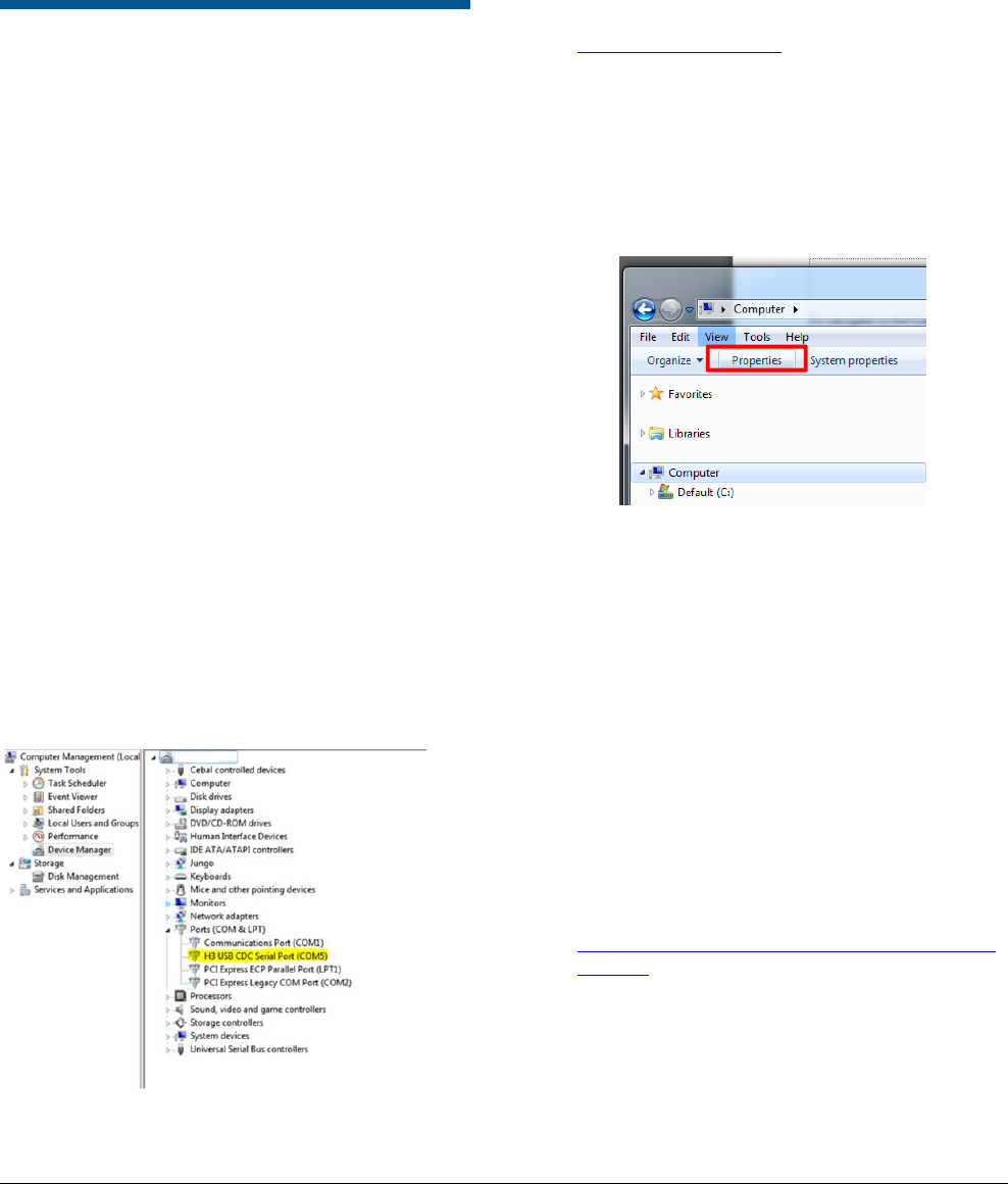
Laptop Setup and Use
1. Connect the included Micro-USB to USB-B
cable to the phasing tool. Then connect the
other end to a laptop. If the H3 USB Serial port
driver is already installed, the laptop assigns a
Com port to the phasing tool. To determine
which port was assigned, open the computer
management screen and observe the port list.
The list updates as the port is added. In the
example below, Com port 5 was assigned to
the tool when the cable was plugged in.
To navigate to the Computer Management
screen:
a. Right click Computer on the Start
menu.
b. Select Manage. The Computer
Management window opens.
c. Click on Device Manager. A list of
device types displays.
d. Expand the Ports list to display the
port numbers.
Figure 3. Computer Management Window
Settings
2. PuTTY is used to talk to the tool and the
System Configurator is used to perform the
phase adjustment.
The phasing tool displays the phase delta and
other information on the laptop using PuTTY as the
interface.
1. Install the provided USB driver. This is
included in the ADS4 bundle available on
www.sensormatic.com.
To install the USB driver, perform the following
steps.
a) In windows explorer navigate to your C
drive and select System Properties
from the top menu.
Figure 4.System Properties
b) Select Device Manager and expand
the Ports menu. You see a question
mark icon beside the
Communications Port.
c) Right click and select Update Driver
Software.
d) Select Browse my computer for
driver software.
e) Navigate to C:\Program Files
(x86)\Sensormatic\ADS4 Platform
Software\Release XXXX\Driver.
f) Click the installation file and follow the
wizard to install the driver.
2. Launch PuTTY. It can be downloaded at the
following address.
https://the.earth.li/~sgtatham/putty/latest/x86/p
utty.exe
3. Select Serial Communication and enter the
com port which corresponds to the USB port
that the phase tool is connected to.
4. Enter the Speed manually as 115200.
Preliminary
ULTRA MAX PHASING TOOL 8000-2579-49 REV. B
USER GUIDE
5 of 9
8000-2579-49
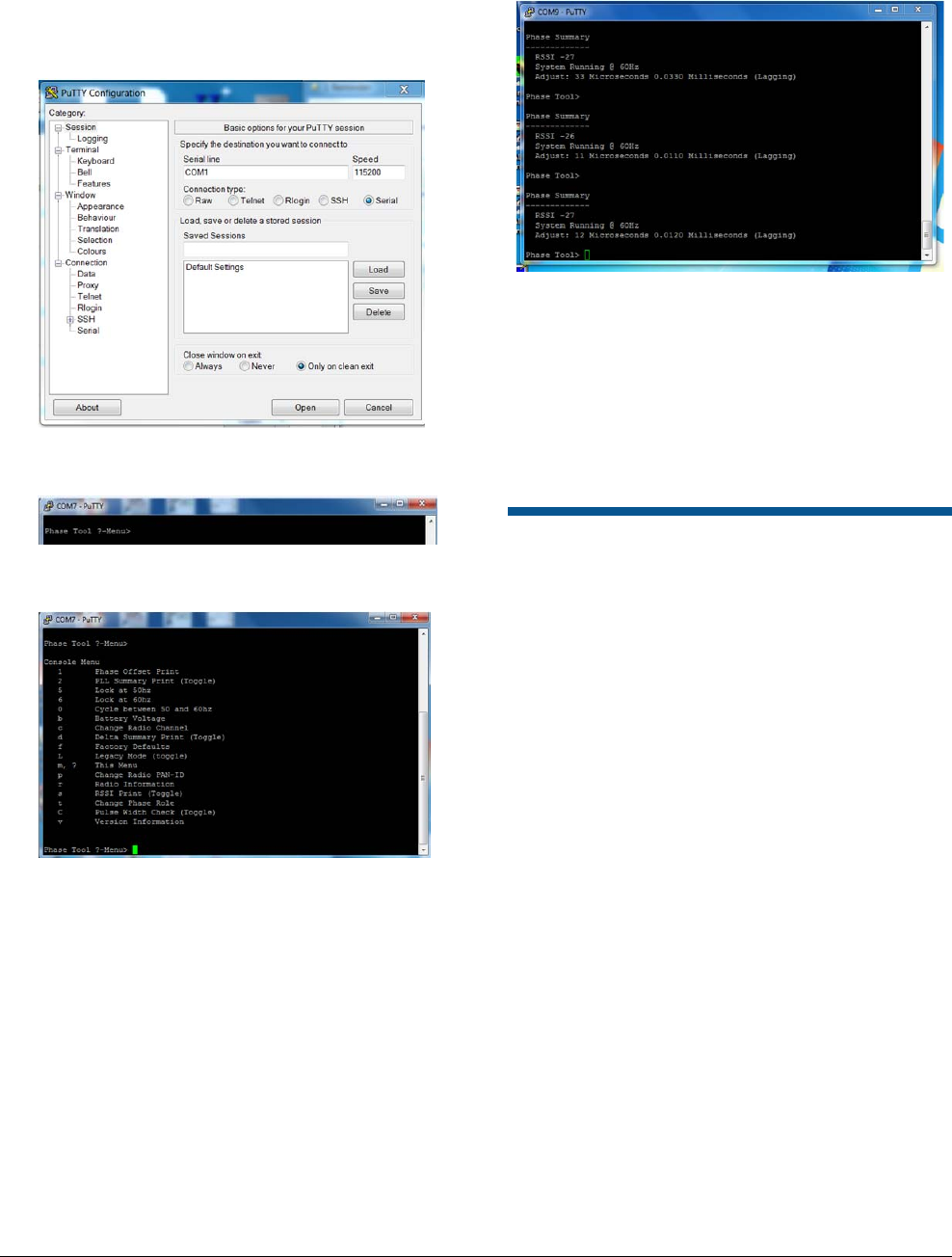
5. Select Open to open the console window.
Below is an example of the PuTTY initialization
screen.
Figure 5. PuTTY Configuration
6. Note: To query the PuTTY, select ? as shown
below.
The Console Menu displays again. See image
below.
7. The PuTTY screen launches. Figure 6 shows
an example of the PuTTY input screen.
Figure 6. Example of PuTTY screen
8. To display the phase delta, press enter, and
then type 1 in the command line. This shows if
the signal from the system being phased is
leading or lagging from the reference system.
The value is displayed in microseconds and
milliseconds for convenience.
Note: Refer to the appendix for a list of PuTTY
commands.
Adjusting the Phase
1. Open the standard configurator (eg. ADS4,
UltraPost) for the system which is being
phased. Use the phase adjustment slider on
the configurator to adjust the phase by the
amount indicated on the phase delta display.
Note: For Legacy equipment see Phasing
steps for Legacy M4K controller in the
Appendix.
2. Check the phase delta again by typing “d” on
the command line of the PuTTY interface. If
the delta in microseconds is close to zero
(within plus or minus 50µS), then the phasing
is complete. If not, adjust the phase again and
recheck.
3. Repeat for each system which requires
phasing.
Preliminary
ULTRA MAX PHASING TOOL 8000-2579-49 REV. B
USER GUIDE
6 of 9
8000-2579-49
Appendix
List of PuTTY Commands
Command Syntax
1 Phase Offset Print (Toggle)
2 PLL Summary Print (Toggle)
5 Lock at 50hz
6 Lock at 60hz
0 Cycle between 50 and 60hz
b Battery Voltage
c Change Radio Channel
d Delta Summary Print (Toggle)
f Factory defaults
L Legacy Mode (toggle)
m This Menu
p Change Radio PAN-ID
r Radio Information
s RSSI Print (Toggle)
t Change Phase Role
C Pulse Width Check (Toggle)
v Version Information
*If you encounter a system which doesn’t lock to
the Tx signal, enter the C (uppercase C) command
in the PuTTY screen and the tool locks to other
equipment with a shorter pulse width.
PAN ID Setup
The same PAN ID and radio channel must be set
on the phasing tools for them to communicate.
Connect to a laptop and use PuTTY to adjust the
PAN ID or channel if necessary.
Type p in the command line to change the PAN ID.
Enter the new PAN ID and press enter.
Channel selection set up
To change the radio’s channel, type c in the
command line. Enter the new channel number and
press enter.
The channels selections are between 11-25.
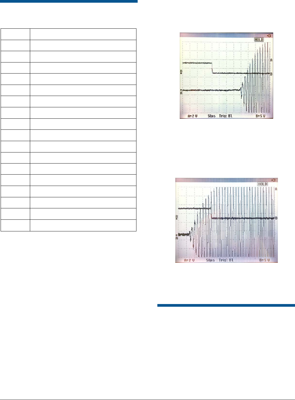
Phasing Tools Comparison
Figure 10. Phase Lagging Reading on the
Oscilloscope
The scope image in figure 7 shows the system that
is being phased is lagging behind the reference
system. The AMX-1000 phasing shows that a
negative adjustment value is required to phase the
system.
Figure 11. Phase Leading Reading on the
Oscilloscope.
The scope image in figure 8 shows the system
being phased is leading the reference system. The
AMX-1000 phasing tool shows that the system is
leading and shows that a positive adjustment value
is required to phase the system.
Phasing steps for Legacy
M4K controller
1. Enable the Line Sync switch on the M4K
controller by flipping the switch up.
2. Turn the potentiometer 10 turns counter
clockwise (left) or until you hear a click.
3.
Turn the potentiometer 3.5 turns clockwise
(right).
Preliminary
ULTRA MAX PHASING TOOL 8000-2579-49 REV. B
USER GUIDE
7 of 9
8000-2579-49
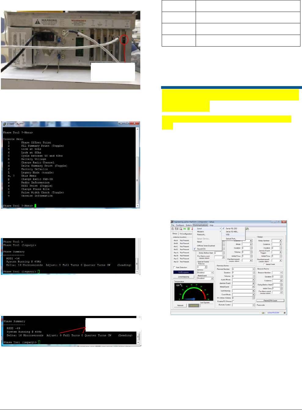
Figure 7. M4K Controller
4. Open the PuTTY screen. The Console Menu
will display. See Figure 8.
Figure 8. PuTTY Screen
On the PuTTY screen, enter the capital letter L for
Legacy mode. The screen will display Phasing
Tool (Legacy)>. See image below.
5. Enter number 1 for Phase Summary display
information. See Figure 9.
Figure 9. PuTTY screen
6. Make adjustments to the potentiometer as per
turns on the PuTTY Phase Summary display.
Continue to enter 1 to get the system Phased.
LED Status Indications
Led Status Phasing State
LED 1 On Phasing is leading
LED 2 On System is In-phased
LED 3 On Phasing is lagging
Note: If Level LED 2 is On, the system is
In-Phased and the procedure is complete.
Note: If Level LED 1 or 3 are On, press 1 on
PuTTY and continue to make adjustments.
Phasing tool firmware update
procedure
Upgrading the Phasing tool application (.s19
file)
Note: Restart the ADS4 configurator between the
update fo the application and the radio.
1. Open the ADS4 Configurator before powering
on the phase tool.
2. If this is the first time running the configurator
with the phasing tool, create a USB endpoint.
Select Communications>Local>USB. In the
New USB Name field enter “Test Port 255”.
Click OK.
Figure 10 Configurator screen
3. Connect the USB cable to the phasing tool and
power on the phasing tool in boot loader mode.
Press both sw1 and sw2 simultaneously to
power on in boot loader mode; the three level
LED’s will be flashing.
4. Choose the COM port. Select
Communications>Local>Select Port. Port
varies on each computer check device
manager.
Location of
potentiometer
Adjustments in turns
Preliminary
ULTRA MAX PHASING TOOL 8000-2579-49 REV. B
USER GUIDE
8 of 9
8000-2579-49
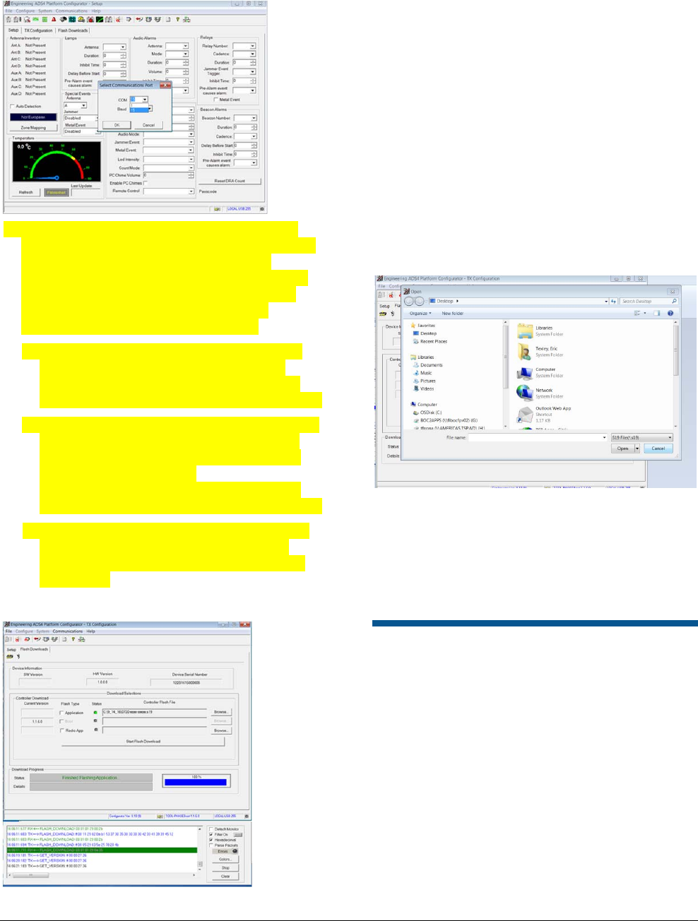
Figure 11. COM port selection
5. Wait for the configurator to connect, this can
take up to twenty seconds. When connection is
made to the unit it will say “Boot utility is
running, please select a file.” By default this is
the phasing tool application. Use Browse to
select the application “.s19 image”. The
application will upgrade automatically.
a. If a dialogue box does not display with the
message “Boot utility is running”, select
Communications>Local>USB to prompt
the configurator to attempt a new connection.
b. If the configurator displays an error when the
port opens do the following: Power off the
phasing tool and power it on again in boot
loader mode. Next select
Communications>Local>USB to prompt
the configurator to attempt a new connection.
c. Close the configurator on completion of the
firmware upgrade. This is to prevent the
phasing tool from resetting and locking the
comm port.
Figure 12.Configurator screen
6. The phasing unit will always reset after a flash
download.
Upgrading the Radio Image (.hex file)
1. Close the configurator application and restart.
2. Start the phasing tool in boot loader mode as
outlined above.
3. Select Communications>Local>USB as
outlined above.
4. When the connection is made to the target the
configurator displays a dialogue box asking for
a radio application. Click Cancel.
5. Click the checkbox for Radio App. Browse to
the radio application file.
Figure 13. Browse for file
6. If the flash download doesn’t start automatically
click Start Flash Download.
7. When the download is complete close the
configurator. Restart the phasing tool and open
PuTTY and check the software versions.
Declarations
Regulatory Information
Radio
Frequency of Operation
Model: AMX-1000
Type ........................................................... AMX-1000
Frequency band .............................. 2400-2483.5 MHz
Maximum power ................................... 4.5 mW EIRP
If frequency is selectable for your model, select only the country
in which you are using the device. Any other selection will make
the operation of this device illegal.

Preliminary
ULTRA MAX PHASING TOOL 8000-2579-49 REV. B
USER GUIDE 9 of 9 8000-2579-49
Approved Antennas
Under Industry Canada regulations, this radio transmitter may
only operate using an antenna of a type and maximum (or
lesser) gain approved for the transmitter by Industry Canada.
To reduce potential radio interference to other users, the
antenna type and its gain should be so chosen that the
equivalent isotropically radiated power (e.i.r.p.) is not more than
that necessary for successful communication.
Conformément à la réglementation d’Industrie Canada, le
présent émetteur radio peut fonctionner avec une antenne d’un
type et d’un gain maximal (ou inférieur) approuvé pour
l’émetteur par Industrie Canada.
Dans le but de réduire les risques de brouillage radioélectrique
à l’intention des autres utilisateurs, il faut choisir le type
d’antenne et son gain de sorte que la puissance isotrope
rayonnée équivalente (p.i.r.e.) ne dépasse pas l’intensité
nécessaire à l’établissement d’une communication satisfaisante.
This radio transmitter IC: 3506A-AMX1000 has been approved
by Industry Canada to operate with the antenna types listed
below with the maximum permissible gain and required antenna
impedance for each antenna type indicated. Antenna types not
included in this list, having a gain greater than the maximum
gain indicated for that type, are strictly prohibited for use with
this device.
Le présent émetteur radio IC: 3506A-AMX1000 a été approuvé
par Industrie Canada pour fonctionner avec les types d’antenne
énumérés ci-dessous et ayant un gain admissible maximal et
l’impédance requise pour chaque type d’antenne. Les types
d’antenne non inclus dans cette liste, ou dont le gain est
supérieur au gain maximal indiqué, sont strictement interdits
pour l’exploitation de l’émetteur.
Pulse/Larsen W1027
Polarization ..................................................... Vertical
Composite gain ............................................... 3.2 dBi
Impedance .................................................... 50 ohms
Pulse/Larsen W1038
Polarization ..................................................... Vertical
Composite gain ............................................... 5.0 dBi
Impedance .................................................... 50 ohms
L-Com model HG2403RD-RSF
Polarization ..................................................... Vertical
Composite gain ............................................... 3.0 dBi
Impedance .................................................... 50 ohms
L-Com model HG2405RD-RSP
Polarization ..................................................... Vertical
Composite gain ............................................... 5.0 dBi
Impedance .................................................... 50 ohms
FCC ID: BVCAMX1000
This device complies with part 15 of the FCC Rules. This device
complies with Industry Canada’s licence-exempt RSSs.
Operation is subject to the following two conditions: (1) This
device may not cause harmful interference, and (2) this device
must accept any interference received, including interference
that may cause undesired operation.
México NOM 121: AMX1000
La operación de este equipo está sujeta a las siguientes dos
condiciones:
1) es posible que este equipo o dispositivo no cause
interferencia perjudicial y
2) este equipo debe aceptar cualquier interferencia, incluyendo
la que pueda causar su propia operación no deseada.
INTERNATIONAL ID: AMX1000
EMC ....................................................... 47 CFR, Part 15
EN 300 328
EN 301 489-1
EN 301 489-3
EN 301 489-17
RSS 210
Safety .................................. UL 60950-1 (second edition)
CSA C22.2.60950-1
EN 60950-1
EQUIPMENT MODIFICATION CAUTION: Equipment changes
or modifications not expressly approved by Sensormatic
Electronics, LLC, the party responsible for FCC compliance,
could void the user’s authority to operate the equipment and
could create a hazardous condition.
See ‘About the product’ on page 1.
Other Declarations
WARRANTY DISCLAIMER: Sensormatic Electronics, LLC
makes no representation or warranty with respect to the
contents hereof and specifically disclaims any implied
warranties of merchantability or fitness for any particular
purpose. Further, Sensormatic Electronics, LLC reserves the
right to revise this publication and make changes from time to
time in the content hereof without obligation of Sensormatic
Electronics, LLC to notify any person of such revision or
changes.
LIMITED RIGHTS NOTICE: For units of the Department of
Defense, all documentation and manuals were developed at
private expense and no part of it was developed using
Government Funds. The restrictions governing the use and
disclosure of technical data marked with this legend are set
forth in the definition of “limited rights” in paragraph (a) (15) of
the clause of DFARS 252.227.7013. Unpublished - rights
reserved under the Copyright Laws of the United States.
TRADEMARK NOTICE: Sensormatic is a registered trademark
of Sensormatic Electronics, LLC. Other product names
mentioned herein may be trademarks or registered trademarks
of Sensormatic or other companies.
No part of this guide may be reproduced in any form without
written permission from Sensormatic Electronics, LLC.