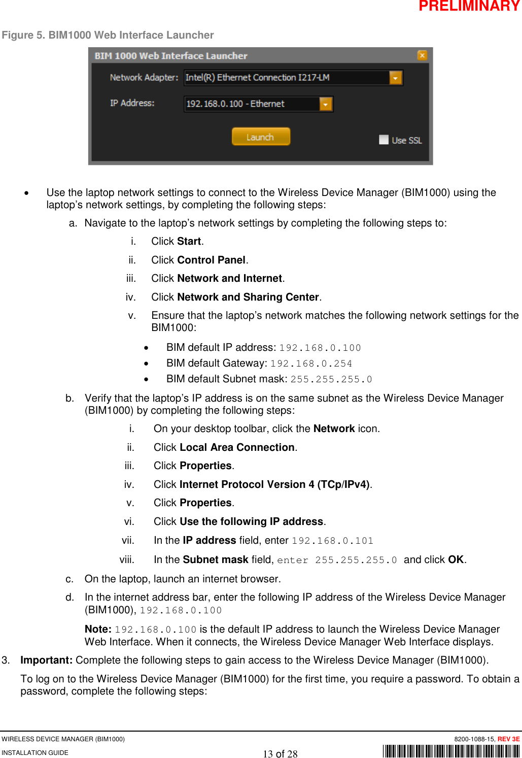
Tyco Safety Sensormatic BIM1000 Business Intelligence Module User Manual REV

Tyco Safety Products/Sensormatic Business Intelligence Module REV

Contents

User manual_REV

PRELIMINARY WIRELESS DEVICE MANAGER (BIM1000) 8200-1088-03 REV 4D INSTALLATION GUIDE 1 of 28        *8200-1088-03* Wireless Device Manager (BIM1000) Installation Guide  BIM1000  © 2018 Sensormatic Electronics, LLC
PRELIMINARY WIRELESS DEVICE MANAGER (BIM1000) 8200-1088-03 REV 4D INSTALLATION GUIDE 2 of 28        *8200-1088-03* Contents About this guide ..................................................................................................................................... 3 Additional documentation .................................................................................................................... 3 Technical Support ............................................................................................................................... 3 Training ................................................................................................................................................ 3 About the product ....................................................................................................................................... 4 Features .............................................................................................................................................. 4 Compatibility ........................................................................................................................................ 4 Part numbers ....................................................................................................................................... 6 Tools required ..................................................................................................................................... 6 Section I: Before you begin ........................................................................................................................ 7 Survey and planning requirements ...................................................................................................... 7 Survey requirements ........................................................................................................................... 7 Network Topology Map requirements ................................................................................................. 8 Application and firmware requirements ............................................................................................... 8 TrueVUE requirements ........................................................................................................................ 9 Laptop requirements ........................................................................................................................... 9 Component installation requirements ................................................................................................. 9 Electrical power requirements ............................................................................................................. 9 Wiring requirements ............................................................................................................................ 9 Safety ..................................................................................................................................................... 10 Installation prerequisites ..................................................................................................................... 10 Section II: Installation sequence overview ............................................................................................. 11 Section III: Connecting the Wireless Device Manager (BIM1000) ........................................................ 12 Overview of connection steps ............................................................................................................ 12 Step 1: Connecting the Wireless Device Manager ............................................................................ 12 Ethernet cable set-up ........................................................................................................................ 12 USB set-up ........................................................................................................................................ 15 Step 2: Commissioning the Wireless Device Manager .................................................................... 17 Step 3: Verifying the Wireless Device Manager ................................................................................ 18 Step 4: Optional: Installing a cellular modem ................................................................................... 18 Section IV: Installing the Wireless Device Manager (BIM1000) ............................................................ 19 Overview of steps ................................................................................................................................. 19 Step 1: Locating the Wireless Device Manager ................................................................................ 19 Step 2: Mounting the Wireless Device Manager ............................................................................... 20 Mounting the Wireless Device Manager to a surface-mounted electrical box .................................. 20 Mounting the Wireless Device Manager to a hollow cavity wall ........................................................ 21 Mounting the Wireless Device Manager to the ceiling ...................................................................... 23 Step 3: Powering on the Wireless Device Manager .......................................................................... 25 Section V: Securing the Wireless Device Manager ............................................................................... 25 Removing the Wireless Device Manager from the mounting bracket ............................................... 25 Specifications ............................................................................................................................................ 26 Declarations ............................................................................................................................................... 27 Other declarations ..................................................................................................................................... 28
PRELIMINARY WIRELESS DEVICE MANAGER (BIM1000) 8200-1088-03 REV 4D INSTALLATION GUIDE 3 of 28        *8200-1088-03* About this guide This installation guide explains how to install the Wireless Device Manager (BIM1000) with the Wireless Device Module (BIX1000), to synchronize and aggregate data from all Sensormatic-connected devices.  Additional documentation The following is a list of additional documents related to this installation: • Wireless Device Module (BIX1000) Installation Guide, 8200-1088-15. • Wireless Device Manager (BIM1000) and Wireless Device Module (BIX1000) Setup Guide, 8200-1088-01.  • Ultra Post® IV AMS-1012 Wireless Device Module (BIX1000) Cable Kit Installation Guide,  8200-1088-05. • Ultra Post® VI AMS-1014 Wireless Device Module (BIX1000) Cable Kit Installation Guide,  8200-1088-06. • Ultra 1.8 Meter ABS Pedestal Wireless Device Module (BIX1000) Cable Kit Installation Guide,  8200-1088-07. • AMB9010-IPS and AMB-1200 Label Deactivator Controller Wireless Device Module (BIX1000) Cable Kit Installation Guide, 8200-1088-08. • AMS-9050 Controller Wireless Device Module (BIX1000) Cable Kit Installation Guide,  8200-1088-09. • AMS-9040 Controller Wireless Device Module (BIX1000) Cable Kit Installation Guide,  8200-1088-10. • AMS-9060 Controller and AMS-1170-2C/4C Controller Wireless Device Module (BIX1000) Cable Kit Installation Guide, 8200-1088-11. • ZBSMPROE ScanMax® Pro Label Deactivator Controller Wireless Device Module (BIX1000) Cable Kit Installation Guide, 8200-1088-12. • IDKM-10XX/AMK-10XX SuperTag® Detacher Wireless Device Module (BIX1000) Cable Kit Installation Guide, 8200-1088-13. • AMB-2011/AMB-1101/ZBAMB9010 EAS Label Deactivator Wireless Device Module (BIX1000) Cable Kit Installation Guide, 8200-1088-16. • Wireless Device Module (BIX1000) Extension Cable Kit Installation Guide, 8200-1088-14. • AMS-1080 Controller Wireless Device Module (BIX1000) Cable Kit Installation Guide,  8200-1088-17. Technical Support For product bulletins, and the most recent updates to this guide, visit https://sensormaticsecurelogin.com. Training  WARNING: Do not install a Wireless Device Manager (BIM1000) unless you have completed the following Wireless Device Manager (BIM/BIX) Training Curriculum modules: • BIM and BIX Installation Technical Training. • BIM Configuration Technical Training. • Optional: SMaaS Overview Sales Training.
PRELIMINARY WIRELESS DEVICE MANAGER (BIM1000) 8200-1088-03 REV 4D INSTALLATION GUIDE 4 of 28        *8200-1088-03* About the product The Wireless Device Manager (BIM1000) is a wireless access point that uses an IEEE 802.15.4 wireless standard to connect to the Wireless Device Module (BIX1000).  The Wireless Device Module (BIX1000) uses the IEEE 802.15.4 wireless protocol to connect to the Wireless Device Manager (BIM1000) to synchronize all in-store Sensormatic-connected deactivation and detection controllers to collect data, and to provide a health status for all the connected devices. For an example, see Figure 1 on page 5, and Figure 3 on page 7. The synchronization between the deactivation and the detection controllers minimizes failed deactivation at the Point-of-Sale (POS) and nuisance alarms at the store exit area. The data collected includes alarms, events, and people-counting statistics. It also collects alarm input responses through an Android tablet device.  Customers can use a desktop browser to log into a TrueVUE reporting platform, or a Shrink Management as a Service (SMaaS) platform, to access historical daily data reports from all the connected devices. The customer can also use an Android tablet device for alarm input responses.  Features The Wireless Device Manager (BIM1000) has the following features: • An embedded web configurator. • A wired EAS Network (RS-485). • A wireless EAS Network, 802.15.4  • A wireless 802.11.B/G/N (Client and Soft AP). • It can support 32 devices on each port, supporting 64 devices in total. • MicroSD flash storage. • Micro USB Type B access. • Bluetooth radio for wireless setup and service.  Compatibility The Wireless Device Manager (BIM1000) is compatible with the following devices with the Wireless Device Module (BIX1000):  • The Ultra Post® IV AMS-1012 Pedestal. • The Ultra Post® VI AMS-1014 Pedestal. • The Ultra 1.8 Meter ABS Pedestal. • The AMS-9060 Controller. • The AMS-9050 Controller. • The AMS-9040 Controller. • The AMS-1080 Controller.  • The AMS-1170-2C/4C Controller. • The ZBAMB9010 EAS Label Deactivator Controller. • The AMB9010-IPS EAS Label Deactivator Controller. • The ZBSMPROE ScanMax® Pro Label Deactivator Controller. • The AMB-1200C EAS Label Deactivator Controller. • The AMK-1000 and the AMK-1010 SuperTag® Detacher. • The IDKM-1000 and the IDKM-1010 SuperTag® Detacher. • The AMB-2011 Value Pad II Countertop EAS Label Deactivator. • The AMB-1101 VersaPass II Countertop EAS Label Deactivator.
PRELIMINARY WIRELESS DEVICE MANAGER (BIM1000) 8200-1088-03 REV 4D INSTALLATION GUIDE 5 of 28        *8200-1088-03* Figure 1. Wireless Device Manager (BIM1000) and BIM1000 mounting bracket  A BIM1000, 0304-0170-01 B Speaker C RGB visual display D Micro USB port E Locking tab F Radio antenna (802.15.4)  Note: You can identify the radio antenna by its yellow connector G Wif-Fi antenna Note: You can identify the Wi-Fi antenna by its silver connector   H BIM1000 mounting bracket, 0404-1247-01 Note: You can mount the Wireless Device Manager to a hollow cavity wall, to a ceiling, or to a surface-mounted electrical box using the BIM1000 mounting bracket. Ensure you commission the BIM1000 and verify its operation before you attach the BIM1000 module to the mounting bracket.  Figure 2. Back view of Wireless Device Manager, 0304-0170-01   A Reset button B Power port C Ethernet port D RS485 port E Locking tab F Tamper switch A B C E F G D A B C D D E F H
PRELIMINARY WIRELESS DEVICE MANAGER (BIM1000) 8200-1088-03 REV 4D INSTALLATION GUIDE 6 of 28        *8200-1088-03* Part numbers Table 1 lists the part numbers you require to install a Wireless Device Manager (BIM1000). Table 1. Wireless Device Manager (BIM1000) part numbers Part number Description Quantity 0352-0766-01 BIM1000 Installation Kit  1 1400-0033-01  T-bar clip   2 1400-0205-01  T-bar clip, 1/4-20, 5/8” L, 15/16” W  1 2838-0015-01 Flange nut, 1/4-20, 7/16 WAF  2 2880-0070-01 Toggle bolt, 1/4-20 x 6.00  1 2880-0094-01 Anchor, self-drill, with screws, #8 x 1-1/4   2 0304-0170-01 BIM1000 module  1 0404-1247-01 BIM1000 mounting bracket  1 3411-0027-01 Antenna  1 5606-0131-01  BIM1000 power supply Note: You must order the BIM1000 power supply separately.  1 0652-0897-01  BIM1000 power supply extended cable kit Note: You must order the BIM1000 power supply extended cable kit separately. 1 6003-0313-01 Micro USB-B to USB-B cable, 1.8m Note: You must order the micro USB-B to USB-B cable separately. 1 Tools required Confirm that you have the following tools before you install a Wireless Device Manager (BIM1000): • A #2 Philips head screwdriver. • A cable tester. • A digital voltmeter. • A micro USB cable, 6003-0313-01, or an Ethernet patch cable.  • A drill, and assorted drill-bits.  • A drywall saw.
PRELIMINARY WIRELESS DEVICE MANAGER (BIM1000) 8200-1088-03 REV 4D INSTALLATION GUIDE 7 of 28        *8200-1088-03* Section I: Before you begin Before you install a Wireless Device Manager (BIM1000), ensure that you adhere to the criteria in the following sections. Survey and planning requirements This section outlines the site survey and planning requirements, and the systems requirements that are critical to the correct installation of a Wireless Device Manager (BIM1000).  Figure 3. Overview of the Wireless Device Manager (BIM1000) solution  A Internet E LP Manager B Gateway F Wireless Device Module (BIX1000) C Network switch G Wireless Device Manager (BIM1000) D Wireless Access Point (802.11 Wi-Fi)   Survey requirements You must access the following information before you proceed with the installation of a BIM1000: • The layout and design of the installation site. • The location of each BIM1000 module. You can obtain this information from the Network Typology Map.  • Identify each BIX1000 you need to program to each BIM1000 module.    802.11 Wi-Fi 802.15.4 Wi-Fi A B C D E F G F
PRELIMINARY WIRELESS DEVICE MANAGER (BIM1000) 8200-1088-03 REV 4D INSTALLATION GUIDE 8 of 28        *8200-1088-03* Network Topology Map requirements You require the following information for each device you place on the network for the Wireless Device Manager (BIM1000) to work with a Wireless Device Module (BIX1000). This information is in the Network Topology Map that the project manager or the coordinator for the account supplies, or in the IP Request form document that the customer’s IT department supplies.  • The location of each BIM1000 module. • The switch location, name, and port number. • Any Wi-Fi restrictions, if setting up the BIM1000 to operate in Access Point (AP) mode. • The Wi-Fi channel.  Note: The Wi-Fi channel is dependent on the region of installation.  • The Wi-Fi access point location and the Service Set Identifier (SSID).  • A static or a dynamic IP address. • The subnet mask. • The gateway • The Network Time Protocol (NTP) Server. • The Ethernet MAC address. • The Wi-Fi Subnet Mask.  • The Wi-Fi Default Gateway. • The SIP server address. Application and firmware requirements To support the installation of a Wireless Device Manager (BIM1000), you must download the latest firmware bundle, 1.00 or later, and the BIM Web Launch Tool from https://sensormaticsecurelogin.com/.  To download the BIM Web Launch Tool, complete the following steps: 1. Open a web browser and launch https://sensormaticsecurelogin.com/. 2. Enter your valid log on information and click Login. 3. From the Tech Support menu, click EAS. 4. Click Software Download. 5. Click BIM Web Launch Tool. 6. To download the software bundle, click the link, and save the file to a local folder on your laptop.  7. Log out of www.sensormaticsecurelogin.com/. 8. On your laptop, rename the file you saved to an .exe file. Click the executable file, and click Run. 9. Follow the setup wizard instructions to save the software on your laptop.  Note: Files save to the following location: C:\Program Files\Sensormatic\BIM Software Bundle (Program Files (x86) for 64 bit machines).
PRELIMINARY WIRELESS DEVICE MANAGER (BIM1000) 8200-1088-03 REV 4D INSTALLATION GUIDE 9 of 28        *8200-1088-03* TrueVUE requirements To support TrueVUE reports for a Wireless Device Manager (BIM1000) installation, you require the following: • TrueVUE version 7.4 or later. • The SIP URL as specified in the Network Topology Map.  • Valid service credentials, if authentication is necessary. • The store name, the store number, and the division number.  • The heartbeat interval.  • Ensure that the appropriate port is open, typically port 8080 or 8081. Laptop requirements You require the following items for your laptop: • Microsoft® Internet Explorer® version 11, or Mozilla® Firefox® version 56, or Google® Chrome® version 64, browser installed.  Note: Ensure that JavaScript blockers are disabled on the web browser.  • A USB port.  • An Ethernet adapter. Component installation requirements This section outlines the component installation requirements to install a Wireless Device Manager (BIM1000). Electrical power requirements Confirm the following electrical power requirements are in place to install a Wireless Device Manager (BIM1000): • The AC power cord could be carrying 120Vac or 240Vac. The AC source must be a 2-wire type with ground. It also must be a 24-hour, unswitched outlet with less than 0.5Vac between neutral and ground. Note: The BIM1000 takes its Sync signal from this AC power source.  • The BIM1000 can operate from generator supplied AC power if it meets the AC power requirements.  Important: You must select Generator Mode when configuring the BIM1000 for use in multiple generator environments.  Wiring requirements Confirm the following wiring requirements are in place for each piece of hardware before you install a Wireless Device Manager (BIM1000): • RS-485 cabling, including the termination of cabling, the pinouts, and a diagram with RS485-High,  RS485-Low, and Sync connections outlined.  • All Ethernet patch cables must be CAT5e, CAT6, or CAT6e.
PRELIMINARY WIRELESS DEVICE MANAGER (BIM1000) 8200-1088-03 REV 4D INSTALLATION GUIDE 10 of 28        *8200-1088-03* Safety You must adhere to the following safety instructions when you install a Wireless Device Manager (BIM1000): WARNING: Risk of electric shock Disconnect all power sources before servicing. • Do not install the Wireless Device Manager (BIM1000) in a plenum or other environmental air-handling space. • You must use plenum-rated cables, unless the cables are in raceways. • Installation of the BIM1000 must comply with the latest national electrical codes, national fire code, and all applicable local codes and ordinances. National or local wiring codes may differ between regions. Adherence to these codes supersedes instructions in this document.  • You must observe and respect all the safety instructions in this installation guide, and or the operation of the Wireless Device Manager (BIM1000).  • You must mount the Wireless Device Manager (BIM1000) only as instructed in this installation guide. Mounting the Wireless Device Manager (BIM1000) any other way can affect its operation. • The manufacturer is not responsible for any radio or TV interference caused by unauthorized modifications to this equipment. Such modifications can void the user’s authority to operate the equipment.  • You must install the antennas for this transmitter with a separation distance of at least 20 centimetres  (8 inches) from all persons, and must not be co-located or operating in conjunction with any other antenna or transmitter. Installation prerequisites  To install a Wireless Device Manager (BIM1000), you must have the following prerequisites in place before you proceed: • Do you have the Network Topology Map requirements, or IP Request Form? • Do you have the location of each BIM1000 identified? You can obtain this information from the Network Typology Map. • Is there power and data, for example Ethernet, Wi-Fi, or 4G gateways where you plan on locating the BIM1000? • Do you have the applicable network ports open for functionality and device management support? • Have you completed the necessary training required to install the Wireless Device Manager (BIM1000)?
PRELIMINARY WIRELESS DEVICE MODULE (BIM1000)             8200-1088-03, REV 4C INSTALLATION GUIDE    11 of 28             *8200-1088-15* Section II: Installation sequence overview Figure 4 gives an overview of the complete installation sequence you must follow when you install a BIM1000 and a BIX1000. You must install the Wireless Device Manager (BIM1000) before you install the Wireless Device Module (BIX1000).  Figure 4. BIM1000 and BIX1000 complete installation sequence  Important: This installation guide only describes the following steps in the complete BIM1000 and BIX1000 installation sequence: • Before you begin: Planning and prerequisites • Step 1: Install the BIM1000  Before you begin: Planning and prerequisites Step 2: Install the BIX1000 cable kits Step 4: Install and locate the BIX1000 Step 5: Validate BIM1000 configuration Step 6: Validate BIM1000 remote connectivity Install the BIM1000. Turn on the BIM1000, and program the PAN ID and the Channel Install the relevant BIX1000 cable kit, and configure the EAS devices Install and locate the BIX1000 Validate the complete BIM1000 and BIX1000 configuration Validate the remote connectivity and data transportation of the BIM1000 Commission the BIX1000 Step 3: Commission the BIX1000 Step 1: Install the BIM1000 Confirm all the prerequisites in Section I are complete before beginning installation
PRELIMINARY WIRELESS DEVICE MANAGER (BIM1000)      8200-1088-15, REV 3E INSTALLATION GUIDE    12 of 28        *8200-1088-15* Section III: Connecting the Wireless Device Manager (BIM1000) This section outlines how to connect the Wireless Device Manager (BIM1000). Overview of connection steps This section gives an overview of the steps involved in connecting a Wireless Device Manager (BIM1000). • Step 1: Connecting the Wireless Device Manager. • Step 2: Commissioning the Wireless Device Manager. • Step 3: Verifying the Wireless Device Manager. • Step 4: Optional: Connecting to a cellular modem Step 1: Connecting the Wireless Device Manager You can connect the Wireless Device Manager (BIM1000) in the following ways: • An Ethernet cable set-up • A USB set-up • A Wi-Fi set-up • A Bluetooth set-up Note: Wi-Fi and Bluetooth are disabled by default. To connect to the BIM1000 module using a Wi-Fi or a Bluetooth set-up, refer to the Wireless Device Manager (BIM1000) and Wireless Device Module (BIX1000) Setup Guide, 8200-1088-01.  Ethernet cable set-up  To connect a Wireless Device Manager (BIM1000) using an Ethernet cable set-up, complete the following steps: 1. Connect the Ethernet cable to your laptop and to the Wireless Device Manager (BIM1000).  2.  Connect to the Wireless Device Manager (BIM1000) in one of the following ways: • Use the BIM Web Launch Tool to connect to the Wireless Device Manager (BIM1000), by completing the following steps: a. On your laptop, open the BIM1000 Web Launch Tool. For an example of the BIM1000 Web Launcher Interface, see Figure 5 on page 13. b. From the Network Adapter list, select the relevant adapter to create the network interface. c. From the IP Address list, select 192.168.0.100 – Ethernet. Note: 192.168.0.100 is the default IP address to launch the Wireless Device Manager Web Interface. d. Click Launch. Note: This launches a web browser to connect to the Wireless Device Manager (BIM1000).
PRELIMINARY WIRELESS DEVICE MANAGER (BIM1000)      8200-1088-15, REV 3E INSTALLATION GUIDE    13 of 28        *8200-1088-15* Figure 5. BIM1000 Web Interface Launcher  • Use the laptop network settings to connect to the Wireless Device Manager (BIM1000) using the laptop’s network settings, by completing the following steps: a.  Navigate to the laptop’s network settings by completing the following steps to: i. Click Start. ii. Click Control Panel. iii. Click Network and Internet. iv. Click Network and Sharing Center. v. Ensure that the laptop’s network matches the following network settings for the BIM1000: • BIM default IP address: 192.168.0.100 • BIM default Gateway: 192.168.0.254 • BIM default Subnet mask: 255.255.255.0 b.  Verify that the laptop’s IP address is on the same subnet as the Wireless Device Manager (BIM1000) by completing the following steps: i.  On your desktop toolbar, click the Network icon. ii. Click Local Area Connection. iii. Click Properties. iv. Click Internet Protocol Version 4 (TCp/IPv4). v. Click Properties. vi. Click Use the following IP address. vii. In the IP address field, enter 192.168.0.101 viii. In the Subnet mask field, enter 255.255.255.0 and click OK. c. On the laptop, launch an internet browser. d. In the internet address bar, enter the following IP address of the Wireless Device Manager (BIM1000), 192.168.0.100 Note: 192.168.0.100 is the default IP address to launch the Wireless Device Manager Web Interface. When it connects, the Wireless Device Manager Web Interface displays. 3. Important: Complete the following steps to gain access to the Wireless Device Manager (BIM1000). To log on to the Wireless Device Manager (BIM1000) for the first time, you require a password. To obtain a password, complete the following steps:
PRELIMINARY WIRELESS DEVICE MANAGER (BIM1000)      8200-1088-15, REV 3E INSTALLATION GUIDE    14 of 28        *8200-1088-15* a.  In the User Login pane, from the User list, select Service, and then click Generate to generate a challenge string. Note: The generated string is valid for one week only. Do not click the Generate button more than once. If you click the button more than once, you need to obtain another password.  b. Copy the generated string in the Generate Challenge String field.  4. Launch an internet browser and navigate to https://sensormaticsecurelogin.com/. 5. Enter your valid log on details, and click Login. 6. Read the Terms & Conditions, and if you agree, select the check box, and click Agree. 7. From the Tech Support menu, click Configurator Registration, and complete the following steps: a. From the Product Code list, click AMS-9060 Web Configuration UI. b. In the Register Number field, enter the generated challenge string that you copied in step 3.b. c. Click Submit. Note: A challenge string and service password is sent to the email you registered with.
PRELIMINARY WIRELESS DEVICE MANAGER (BIM1000)      8200-1088-15, REV 3E INSTALLATION GUIDE    15 of 28        *8200-1088-15* USB set-up  To connect a Wireless Device Manager (BIM1000) using a micro USB cable, 6003-0313-01, complete the following steps: 1. Connect the micro USB cable, 6003-0313-01, to your laptop and to the Wireless Device Manager (BIM1000). For the location of the micro USB port on the BIM1000, see item D, in Figure 1. 2.  Connect to the Wireless Device Manager (BIM1000) in one of the following ways: • Use the BIM Web Launch Tool to connect to the Wireless Device Manager (BIM1000) by completing the following steps: a. On your laptop, open the BIM Web Launch Tool. b. From the Network Adapter list, select the relevant adapter to create the network interface. c. From the IP Address list, select 192.168.2.100 – USB.  Note: 192.168.0.100 is the default IP address to launch the Wireless Device Manager Web Interface.  d. Click Launch. Note: This launches a web browser to connect to the Wireless Device Manager (BIM1000). • Use the laptop network settings to connect to the Wireless Device Manager (BIM1000) by completing the following steps: a.  Navigate to the laptop’s network settings by completing the following steps to: i. Click Start. ii. Click Control Panel. iii. Click Network and Internet. iv. Click Network and Sharing Center. v. Ensure that the laptop’s network matches the following network settings for the BIM1000: • BIM default IP address: 192.168.2.100 Note: All computer IP addresses must use 101 as the last octet for any interface used with the Wireless Device Manager.  • BIM default Gateway: 192.168.0.254 • BIM default Subnet mask: 255.255.255.0 b.  Verify that the laptop’s IP address is on the same subnet as the Wireless Device Manager (BIM1000) by completing the following steps to: i.  On your desktop toolbar, click the Network icon. ii. Click Local Area Connection. iii. Click Properties. iv. Click Internet Protocol Version 4 (TCp/IPv4). v. Click Properties. vi. Click Use the following IP address. vii. In the IP address field, enter 192.168.2.101 viii. In the Subnet mask field, enter 255.255.255.0 and click OK. c. On the laptop, launch an internet browser.
PRELIMINARY WIRELESS DEVICE MANAGER (BIM1000)      8200-1088-15, REV 3E INSTALLATION GUIDE    16 of 28        *8200-1088-15* d. In the internet address bar, enter the following IP address of the Wireless Device Manager (BIM1000), 192.168.2.100 Note: When it connects, the Wireless Device Manager Web Interface displays.  3. Important: Complete the following steps to gain access to the Wireless Device Manager (BIM1000). To log on to the Wireless Device Manager (BIM1000) for the first time, you require a password. To obtain a password, complete the following steps: a. In the User Login pane, click Generate to generate a challenge string. Note: The generated string is valid for one week only. Do not click the Generate button more than once. If you click the button more than once, you need to obtain another password.  b. Copy the generated string in the Generate Challenge String field. 4. Launch an internet browser and navigate to https://sensormaticsecurelogin.com/. 5. Enter your valid log on details, and click Login. 6. Read the Terms & Conditions, and if you agree, select the check box, and click Agree. 7. From the Tech Support menu, click Configurator Registration, and complete the following steps: a. From the Product Code list, click AMS-9060 Web Configuration UI. b. In the Register Number field, enter the generated challenge string you copied in step 3.b. c. Click Submit. Note: A challenge string and service password is sent to the email you registered.
PRELIMINARY WIRELESS DEVICE MANAGER (BIM1000)      8200-1088-15, REV 3E INSTALLATION GUIDE    17 of 28        *8200-1088-15* Step 2: Commissioning the Wireless Device Manager This section outlines how to commission a Wireless Device Manager (BIM1000):  To commission the Wireless Device Manager (BIM1000), complete the following steps: 1. Return to the Wireless Device Manager web page, and use the challenge string to generate the service password, if necessary. See Step 1: Connecting the Wireless Device Manager. 2. From the BIM Configuration menu, click BIM Status.  3. Ensure that the versions and information in the following fields are correct, and click Save. a. Software Version – 00.07.1, or higher b. Bootloader Version – 00.00.5, or higher c. IP Address – 192.168.0.100 4. Optional: If you need to update the firmware on the BIM1000, complete the following steps: a. From the BIM Configuration menu, click Firmware Update.  b. Click Browse, and select the BIM_BIX_RADIO_CFG_WEB_X_XX tar file. Note: X_XX in the tar file indicates the latest version of the firmware.   c. Click Download.  d. Wait for a Transfer Completed Successfully window to open, and then click OK.  e. Click Update.  f. If the update does not complete successfully, repeat steps a, b, c, d, and e. Note: If the BIM1000 does not update successfully, you may be instructed to perform a factory reset. For further information, contact Technical Support. If you need to perform a factory reset, complete the following steps:  i. From the BIM Configuration menu, click Radio Settings.  ii. Record the values for the Pan ID, Channel, and Power, and then click Save.  iii. From the BIM Configuration menu, click BIM Status. iv. Click Factory Reset.  v. Verify that the following firmware version updated successfully: • Software Version: 00.07.1 • Bootloader version: 00.00.5 • Radio version: 00.32.7 • Wi-Fi version: 2.9.0.0 vi. From the BIM Configuration menu, click Radio Settings, and restore the radio settings.  5. From the BIM Configuration menu, click Network Settings, and enter static IP information, or check the DHCP option to get an assigned IP address.  6. Optional: If required, select the Enable HTTP SSL check box to enable Secure Sockets Layer (SSL) on the web server.  7. From the BIM Configuration menu, click Radio Settings, and complete the following steps: a. In the PAN ID field, enter a value in hex from 0 x 0001 through to 0 x FFFE.  Note: The Personal Area Network (PAN) ID must be unique for each BIM1000.
PRELIMINARY WIRELESS DEVICE MANAGER (BIM1000)      8200-1088-15, REV 3E INSTALLATION GUIDE    18 of 28        *8200-1088-15* b. In the Channel field, enter the channel.  Note: The channel must be unique for each BIM1000. You can set a value from 11 to 26 for IEEE 802.15.4 radio frequencies.  Regulatory restriction: Do not use channel 25 or channel 26 in North America. c. Optional: Click Generate to generate a PAN ID and channel.  d. In the Tx Power field, enter the Tx power value for the country of use, as shown in Table 2.  Table 2. BIM1000 and BIX1000 TX power Device TX power, North America TX power, Europe BIM1000 197 (20dB) 70 (10dB) BIX1000 197 (20dB) 94 (10dB) BIX1000EA 220 (20db) 85 (10db) e. Click Save. Note: Write down the PAN ID and channel details to use later on when you commission the Wireless Device Module (BIX1000).  Step 3: Verifying the Wireless Device Manager  To verify that the Wireless Device Manager (BIM1000) is functioning correctly, complete the following procedure: 1. Launch an internet browser. 2. In the address bar, type 192.168.1.100 and press enter. The Wireless Device Manager Web Interface opens.  3. From the User list, click Service. 4. In the Password field, enter the password.  5. In the BIM Status pane, verify the following: a. Verify the number of devices. b. Verify the number of devices online.  Note: If the Wireless Device Manager is functioning correctly, the number of devices and the number of devices online match. c. In the SIP Server Status pane, verify the last connection time and success percentage. Step 4: Optional: Installing a cellular modem This step is optional if you chose to install a cellular modem. To install a cellular modem, follow the instructions that come with the cellular modem.
PRELIMINARY WIRELESS DEVICE MANAGER (BIM1000)      8200-1088-15, REV 3E INSTALLATION GUIDE    19 of 28        *8200-1088-15* Section IV: Installing the Wireless Device Manager (BIM1000) This section outlines how to install a Wireless Device Manager (BIM1000). Important: You must install the Wireless Device Manager (BIM1000) before you install the Wireless Device Module (BIX1000). Note: You can power on and set-up the Wireless Device Manager (BIM1000) before you install it. To do this, proceed to Step 3: Powering on the Wireless Device Manager on page 25. Overview of steps This section gives an overview of the necessary steps to install a Wireless Device Manager (BIM1000): • Step 1: Locating the Wireless Device Manager (BIM1000). • Step 2: Mounting the Wireless Device Manager (BIM1000). • Step 3: Connecting and securing the Wireless Device Manager (BIM1000). Step 1: Locating the Wireless Device Manager To locate the Wireless Device Manager (BIM1000) correctly, you must adhere to the following guidelines: • Locate the BIM1000 a minimum of 2 feet or 24 inches from the Wireless Device Module (BIX1000). For more information, refer to the Wireless Device Module (BIX1000) Installation Guide, 8200-1088-15. • Table 3 lists the expected maximum line of sight range from BIM1000 to BIM1000 managers, and from BIM1000 to BIX1000 modules. The maximum line of sight ranges are based on environments free of obstructions and interference. The range can significantly degrade from the specified maximums.  Table 3. Expected maximum line of sight ranges between modules Modules Region Expected maximum line of sight range BIM1000 to BIX1000 EU 76.2 meters (250 feet) BIM1000 to BIX1000 US 106.7 meters (350 feet) BIM1000 to BIX1000EA EU 106.7 meters (350 feet) BIM1000 to BIM1000 EU 182.9 meters (600 feet) BIM1000 to BIM1000 US 370 meters (1,217 feet) • You must install the antennas for this transmitter with a separation distance of at least 20 centimetres  (8 inches) from all persons, and must not be co-located or operating in conjunction with any other antenna or transmitter.
PRELIMINARY WIRELESS DEVICE MANAGER (BIM1000)      8200-1088-15, REV 3E INSTALLATION GUIDE    20 of 28        *8200-1088-15* Step 2: Mounting the Wireless Device Manager You can mount the Wireless Device Manager (BIM1000) in one of the following ways: • To a surface-mounted electrical box.  • To a hollow cavity wall.  • To a ceiling. Mounting the Wireless Device Manager to a surface-mounted electrical box To mount the Wireless Device Manager (BIM1000) using a surface-mounted electrical box, you require the following equipment: • A BIM1000 Installation Kit, 0352-0766-01. • A BIM Mounting Plate, 0404-1247-01, supplied with the Wireless Device Manager (BIM1000).  • Electrical boxes: For North America, a contractor can supply quad-type electrical boxes or you can source them locally. For all other geographies, refer to the mounting pattern in Figure 6 to determine the supported locally available electrical boxes.  Figure 6. Mounting hole dimensions on BIM1000 mounting bracket, back view  To mount the Wireless Device Manager (BIM1000) using an electrical box, complete the following steps: 1. Locate the Mounting Bracket, 0404-1247-01, and orientate it with the arrows pointing up to the ceiling. See Figure 7 on page 21. 2. If the electrical box is not mounted, mount the electrical box using appropriate hardware.  3. Remove one or more knockouts on the electrical box. 4. Add strain relief to the knockouts where necessary to prevent the cables from chafing, and then secure the cable entry at the electrical box. 5. Complete the following steps to route the cables through the BIM1000 Mounting Bracket, 0404-1247-01: a. If required, locate the RS485 cable, feed it through the RS485 cable opening on the BIM Mounting Bracket, 0404-1247-01, and then secure the RS485 cable in the provided strain relief notch. For the location of the strain relief notch on the BIM1000, see Figure 8 on page 22. 8.5 cm 8.5 cm 8.4 cm 8.3 cm 6 cm 4.6 cm
PRELIMINARY WIRELESS DEVICE MANAGER (BIM1000)      8200-1088-15, REV 3E INSTALLATION GUIDE    21 of 28        *8200-1088-15* b. Locate the Ethernet cable and feed it through the Ethernet cable opening on the BIM Mounting Bracket,  0404-1247-01, and then secure the Ethernet cable in the provided strain relief notch. c. Locate the power cable from the BIM1000 power supply extended cable kit, 0652-0897-01, and feed the three-pin connector end of the cable through the Power cable opening on the BIM Mounting Bracket, 0404-1247-01, and then secure the cable in the provided strain relief notch.  Note: Installing the Wireless Device Manager (BIM1000) to a 4x4 electrical box provides additional depth for cable connectors.  6. Orientate the Mounting Bracket, 0404-1247-01, with the arrows pointing up, over the electrical box.  7. Use two screws supplied with the electrical box, or two screws compatible with the electrical box, and secure the BIM Mounting Bracket, 0404-1247-01, to the electrical box.  Mounting the Wireless Device Manager to a hollow cavity wall To mount the Wireless Device Manager (BIM1000) to a wall with a hollow cavity, you require the following equipment: • A BIM Mounting Plate, 0404-1247-01, supplied with the Wireless Device Manager (BIM1000).  • A #2 Phillips screwdriver. • A 2-inch (5 centimeters) bell saw, or hole saw. • A drill, with assorted drill bits. • A drywall saw.  To mount a Wireless Device Manager (BIM1000) to a hollow cavity wall, complete the following steps: 1. Locate the BIM Mounting Bracket, 0404-1247-01, and orientate it with the arrows pointing up to the ceiling, as shown in Figure 7.   Important: You must locate the Wireless Device Manager (BIM1000) a minimum of 2 feet (24 inches) from the Wireless Device Module (BIX1000). 2. Use the BIM Mounting Bracket, 0404-1247-01, as a template and with a pencil, mark the mounting holes, and entry holes for the Power, the Ethernet, and the RS485 cables. See Figure 7. Figure 7. Front view of the BIM Mounting Bracket, 0404-1247-01  A Mounting holes B Arrow up indicators C Power cable opening D Ethernet cable opening E RS485 cable opening   A A B B C D E
PRELIMINARY WIRELESS DEVICE MANAGER (BIM1000)      8200-1088-15, REV 3E INSTALLATION GUIDE    22 of 28        *8200-1088-15* 3. Use a hand drill and a 2-inch (5 centimeters) drill-bit to drill the mounting holes on the wall.  4. Use a bell saw, or a hand saw, to cut out the Power, the Ethernet, and the RS485 cable holes. 5. From the BIM1000 Installation Kit, 0352-0766-01, locate two drywall anchors, 2880-0094-01, and insert into the mounting holes in the wall.  6. To prepare the cabling, complete the following steps: a. Locate the RS-485 cable and feed it through the RS485 cable opening on the BIM Mounting Bracket, 0404-1247-01. b. Secure the RS485 cable into the strain relief notch. See Figure 8. Figure 8. BIM Mounting Bracket cable strain relief feature  c. Feed the Ethernet cable through the Ethernet cable opening on the BIM Mounting Bracket,  0404-1247-01.  d. Secure the Ethernet cable into the strain relief notch. See Figure 8. e. Locate the three-pin connector cable from the BIM1000 power supply extended cable kit, and feed it through the Power cable opening on the BIM Mounting Bracket, 0404-1247-01. 7. Secure the three-pin connector from the power cable into the strain relief notch. See Figure 8. 8. Correctly orientate the BIM Mounting Bracket in place, with the up arrows pointing to the ceiling.  9. From the BIM1000 Installation Kit, 0352-0766-01, locate two drywall anchor screws, 2880-0094-01, and use a #2 Phillips screwdriver to secure the BIM Mounting Bracket, 0404-1247-01, to the wall.
PRELIMINARY WIRELESS DEVICE MANAGER (BIM1000)      8200-1088-15, REV 3E INSTALLATION GUIDE    23 of 28        *8200-1088-15* Mounting the Wireless Device Manager to the ceiling To mount the Wireless Device Manager (BIM1000) to the ceiling, you require the following equipment: • A BIM1000 Installation Kit, 0352-0766-01. • A BIM1000 Mounting Bracket, 0404-1247-01, supplied with the Wireless Device Manager (BIM1000).  • A drill with assorted drill bits. • Plywood or a strut channel.  You can mount the Wireless Device Manager (BIM1000) to a hard ceiling, a T-bar of a ceiling grid support, or a suspended ceiling panel using the BIM Mounting Bracket, 0404-1247-01.  Mounting the BIM1000 Mounting Bracket to a hard ceiling To mount the Wireless Device Manager (BIM1000) to a hard ceiling complete the following steps:  Note: If possible, mount the BIM Mounting Bracket into a known structural member using the appropriate hardware. Alternatively, use the supplied toggle bolt, 2880-0070-01, to anchor the BIM1000 Mounting Bracket.  1. Locate the BIM1000 Mounting Bracket, 0404-1247-01 and the BIM1000 Installation Kit, 0352-0766-01. a. Use the BIM Mounting Bracket, 0404-1247-01, as a template, and with a pencil, mark the mounting holes, and the Power cable entry hole. If required, mark the entry locations for the RS485 or the Ethernet patch cables.  2. Use a drill with a 1/2 inch (12.5 millimeter) drill-bit, and drill the mounting hole in the ceiling. 3. Use a drill with a 1/2 inch (12.5 millimeter) drill-bit, and drill a hole for the power cable. If required, also drill a hole or holes for the RS485 or the Ethernet Patch cables.  4. From the BIM1000 Installation Kit, 0352-0766-01, locate the 6-inch toggle bolt, 2880-0070-01.  5. Adjust the toggle bolt to ensure that it can expand once you place it through the ceiling, and ensure that a minimum of a 1/2 inch (12.5 millimeters) of the toggle bolt remains exposed below the ceiling.  6. Thread the BIM1000 Mounting Bracket, 0404-1247-01, onto the toggle bolt, 2880-0070-01, and insert it through the ceiling. 7. Pulling down slightly on the bracket assembly, spin the BIM1000 Mounting Bracket to tighten it.  Note: If you have access to the area above the ceiling, you can tighten the toggle bolt, 2880-0070-01, from this location.  8. Place an additional screw on the BIM1000 Mounting Bracket, 0404-1247-01, to prevent the bracket from spinning or loosening when mounted. Alternatively, place the flange nut, 2838-0015-01, from the BIM1000 Installation Kit, 0352-0766-01, above the toggle bolt to secure the bracket in place.  9.  Route the cables through the BIM1000 Mounting Bracket, 0404-1247-01, by completing the following steps: a. If required, locate the RS485 cable, feed it through the RS485 cable opening on the BIM Mounting Bracket, 0404-1247-01, and then secure the RS485 cable in the provided strain relief notch. For the location of the strain relief notch on the BIM1000, see Figure 8 on page 22. b. Locate the Ethernet cable and feed it through the Ethernet cable opening on the BIM Mounting Bracket,  0404-1247-01, and then secure the Ethernet cable in the provided strain relief notch. c. Locate the power cable, feed the three-pin connector end of the cable through the Power cable opening on the BIM Mounting Bracket, 0404-1247-01, and then secure the cable in the provided strain relief notch.
PRELIMINARY WIRELESS DEVICE MANAGER (BIM1000)      8200-1088-15, REV 3E INSTALLATION GUIDE    24 of 28        *8200-1088-15* Mounting the BIM1000 Mounting Bracket to a T-bar of a suspended ceiling support To attach the BIM Mounting Bracket, 0404-1247-01, to a T-bar of a suspended ceiling support, complete the following steps: 1. Use a hand drill with a xx drill-bit, and drill a hole in the center of the plywood.  2. From the BIM1000 Installation Kit, 0352-0766-01, locate the 6-inch toggle bolt, 2880-0070-01.  3. Insert the toggle bolt, 2880-0070-01, through the plywood, and tighten the two flanged nuts,  2838-0015-01, to secure it to the BIM Mounting Bracket, 0404-1247-01. 4. Sit the plywood across the grid support in the ceiling. 5. From the BIM1000 Installation Kit, 0352-0766-01, locate the two T-bar clips, 1400-0033-01, and clip onto the ceiling grid support to secure in place. 6.  Route the cables through the BIM1000 Mounting Bracket, 0404-1247-01, by completing the following steps: a. If required, locate the RS-485 cable, feed it through the RS485 cable opening on the BIM Mounting Bracket, 0404-1247-01, and then secure the RS485 cable in the provided strain relief notch. For the location of the strain relief notch on the BIM1000, see Figure 8. b. Locate the Ethernet cable and feed it through the Ethernet cable opening on the BIM Mounting Bracket,  0404-1247-01, and then secure the Ethernet cable in the provided strain relief notch. c. Locate the power cable, feed the three-pin connector end of the cable through the Power cable opening on the BIM Mounting Bracket, 0404-1247-01, and then secure the cable in the provided strain relief notch.  Mounting the BIM1000 Mounting Bracket to a suspended ceiling panel To attach the BIM Mounting Bracket, 0404-1247-01, to a suspended ceiling panel, complete the following steps: 1. Use a hand drill with a xx drill-bit, and drill a hole in the center of the plywood.  2. From the BIM1000 Installation Kit, 0352-0766-01, locate the 6-inch toggle bolt, 2880-0070-01.  3. Insert the toggle bolt, 2880-0070-01, through the plywood, and tighten the two flanged nuts,  2838-0015-01, to secure it to the BIM Mounting Bracket, 0404-1247-01. 4. Sit the plywood across the grid support in the ceiling. 5. From the BIM1000 Installation Kit, 0352-0766-01, locate the two T-bar clips, 1400-0033-01, and clip onto the ceiling grid support to secure in place. 6. Complete the following steps to route the cables through the BIM1000 Mounting Bracket, 0404-1247-01: a. If required, locate the RS-485 cable, feed it through the RS485 cable opening on the BIM Mounting Bracket, 0404-1247-01, and then secure the RS485 cable in the provided strain relief notch. For the location of the strain relief notch on the BIM1000, see Figure 8 on page 22. b. Locate the Ethernet cable and feed it through the Ethernet cable opening on the BIM Mounting Bracket,  0404-1247-01, and then secure the Ethernet cable in the provided strain relief notch. c. Locate the power cable, feed the three-pin connector end of the cable through the Power cable opening on the BIM Mounting Bracket, 0404-1247-01, and then secure the cable in the provided strain relief notch.
PRELIMINARY WIRELESS DEVICE MANAGER (BIM1000)      8200-1088-15, REV 3E INSTALLATION GUIDE    25 of 28        *8200-1088-15* Step 3: Powering on the Wireless Device Manager To supply power to the Wireless Device Manager (BIM1000) and connect the Ethernet and RS485 cables, complete the following steps:  1. Insert the three-pin connector from the power cable to the Power port on the back of the Wireless Device Manager (BIM1000). For the location of the power port on the BIM1000, see Figure 2 on page 5. 2. Insert the Ethernet cable to the Ethernet port on the back of the Wireless Device Manager (BIM1000). For the location of the Ethernet port on the BIM1000, see Figure 2 on page 5. 3. Insert the RS485 cable to the RS485 port on the back of the Wireless Device Manager (BIM1000). For the location of the RS485 port on the BIM1000, see Figure 2 on page 5.  Section V: Securing the Wireless Device Manager To secure the Wireless Device Manager (BIM1000) to the BIM1000 Mounting Bracket, 0404-1247-01, complete the following steps: 1. Align the Wireless Device Manager (BIM1000) to the BIM Mounting Bracket, 0404-1247-01, as shown in Figure 9. 2. Insert the Wireless Device Manager (BIM1000) to the BIM Mounting Bracket, 0404-1247-01, and rotate counter-clockwise to engage the locking tab, as shown in Figure 9. Figure 9. Securing the Wireless Device Manager (BIM1000) to the BIM Mounting Bracket,   Removing the Wireless Device Manager from the mounting bracket To remove the Wireless Device Manager (BIM1000) from the Mounting Bracket, 0404-1247-01, complete the following steps: 1. Use a small, flat screwdriver to push lightly on the tamper switch on the left-hand side of the Wireless Device Manager (BIM) to disengage the locking tab. For the location of the locking tab on the BIM1000, see Figure 1 on page 5. 2. Rotate the Wireless Device Manager (BIM) counter-clockwise to release it from the BIM1000 Mounting Bracket, 0404-1247-01. 1 2 3
PRELIMINARY WIRELESS DEVICE MANAGER (BIM1000)      8200-1088-15, REV 3E INSTALLATION GUIDE    26 of 28        *8200-1088-15* Specifications Electrical Power supply Primary input ......................................................................................................................................................................... ............................................................... 18VDC input, Sync and RS485 through RJ45 8 pin header with LEDs for RS485. Environmental Ambient temperature .......................................................  ........................................................ 0°C to 50°C (32°F to 122°F) Relative humidity .............................................................  ............................................................ 0 to 90% non-condensing Enclosure Rating .............................................................  ..................................................................................... UL94 V-O Evaluated for altitudes less than 2,000 meters (6,561.68 feet) Mechanical Material: ...........................................................................  .............................................................................................. ABS Color:  ..............................................................................  ..................................................................................... Light grey Dimensions:  ....................................................................  ........................................ 139.52 mm X 114.76 mm X 62.10 mm Weight (approx.):  ............................................................  ............................................................................ 419 g (0.92 lbs) Dimensions Figure 10. Wireless Device Manager (BIM) dimensions, front view  114.76 mm (4.5 in) 139.52 mm (5.5) in 94.50 mm (3.7 in) 62.10 mm (2.4 in) 81.50 mm (3.2 in) 138.82 mm (5.5 in)
PRELIMINARY WIRELESS DEVICE MANAGER (BIM1000)      8200-1088-15, REV 3E INSTALLATION GUIDE    27 of 28        *8200-1088-15* Declarations Model: BIM1000 Regulatory information Contains the following radios; FCC ID: A8TBM78ABCDEFGH, Z64-CC3100MODR1 IC ID: 12246A-BM78SPPS5M2, 451I-CC3100MODR1 Radio Frequency of operation Type.......................................................... .............................................................................................................  BIM1000 Frequency band............................. ...................................................................................................... 2402.0 - 2480.0 MHz ............................................................................................................................................................. 2412.0 – 2462.0 MHz Maximum power ...................................  ..................................................................................................... 10 mW in the EU........................................................................................................................................................................ 100 mW in NA  If frequency is selectable for your model, select only the country in which you are using the device. Any other selection will make the operation of this device illegal.  Approved antennas Under Industry Canada regulations, this radio transmitter may only operate using an antenna of a type and maximum (or lesser) gain approved for the transmitter by Industry Canada. To reduce potential radio interference to other users, the antenna type and its gain should be so chosen that the equivalent isotropically radiated power (e.i.r.p.) is not more than that necessary for successful communication. Conformément à la réglementation d’Industrie Canada, le présent émetteur radio peut fonctionner avec une antenne d’un type et d’un gain maximal (ou inférieur) approuvé pour l’émetteur par Industrie Canada. Dans le but de réduire les risques de brouillage radioélectrique à l’intention des autres utilisateurs, il faut choisir le type d’antenne et son gain de sorte que la puissance isotrope rayonnée équivalente (p.i.r.e.) ne dépasse pas l’intensité nécessaire  à  l’établissement d’une communication satisfaisante. This radio transmitter IC: 3506A-BIM1000 has been approved by Industry Canada to operate with the antenna types listed below with the maximum permissible gain and required antenna impedance for each antenna type indicated. Antenna types not included in this list, having a gain greater than the maximum gain indicated for that type, are strictly prohibited for use with this device. Le présent émetteur radio IC: 3506A-BIM1000 a été approuvé par Industrie Canada pour fonctionner avec les types d’antenne énumérés ci-dessous et ayant un gain admissible maximal et l’impédance requise pour chaque type d’antenne. Les types d’antenne non inclus dans cette liste, ou dont le gain est supérieur au gain maximal indiqué, sont strictement interdits pour l’exploitation de l’émetteur. Pulse/Larsen W1027 Polarization ..................................................... .......................................................................................................... Vertical Composite gain ............................................... ..........................................................................................................  3.2 dBi Impedance ....................................................  ......................................................................................................... 50 ohms Pulse/Larsen W1038 Polarization ..................................................... .......................................................................................................... Vertical Composite gain ...............................................  .......................................................................................................... 3.8 dBi Impedance ....................................................  ......................................................................................................... 50 ohms L-Com model HG2403RD-RSF Polarization ..................................................... .......................................................................................................... Vertical Composite gain ............................................... ........................................................................................................... 3.0 dBi Impedance .................................................... .........................................................................................................  50 ohms
PRELIMINARY WIRELESS DEVICE MANAGER (BIM1000)      8200-1088-15, REV 3E INSTALLATION GUIDE    28 of 28        *8200-1088-15* FCC ID: BVCBIM1000 This device complies with part 15 of the FCC Rules. This device complies with Industry Canada’s licence-exempt RSSs. Operation is subject to the following two conditions: (1) This device may not cause harmful interference, and (2) this device must accept any interference received, including interference that may cause undesired operation.  México NOM 121: BIM1000 La operación de este equipo está sujeta a las siguientes dos condiciones: 1) es posible que este equipo o  dispositivo no cause interferencia perjudicial y 2) este equipo debe aceptar cualquier interferencia, incluyendo la que pueda causar su propia operación no deseada. INTERNATIONAL ID: BIM1000 EMC .......................................................  .................................................................................................... 47 CFR, Part 15 ............................................................................................................................................................................ EN 300 328 ......................................................................................................................................................................... EN 301 489-1 ......................................................................................................................................................................... EN 301 489-3 ....................................................................................................................................................................... EN 301 489-17 ................................................................................................................................................................................ RSS 210 Safety.......................................................... ....................................................................................................  UL/EN 60950-1  ................................................................................................................................................................................... CSA C22.2.60950-1    EQUIPMENT MODIFICATION CAUTION: Equipment changes or modifications not expressly approved by Sensormatic Electronics, LLC, the party responsible for FCC compliance, could void the user’s authority to operate the equipment and could create a hazardous condition. See About this guide on page 3. Other declarations WARRANTY DISCLAIMER: Sensormatic Electronics, LLC makes no representation or warranty with respect to the contents hereof and specifically disclaims any implied warranties of merchantability or fitness for any particular purpose. Further, Sensormatic Electronics, LLC reserves the right to revise this publication and make changes from time to time in the content hereof without obligation of Sensormatic Electronics, LLC to notify any person of such revision or changes. LIMITED RIGHTS NOTICE: For units of the Department of Defense, all documentation and manuals were developed at private expense and no part of it was developed using Government Funds. The restrictions governing the use and disclosure of technical data marked with this legend are set forth in the definition of “limited rights” in paragraph (a) (15) of the clause of DFARS 252.227.7013. Unpublished - rights reserved under the Copyright Laws of the United States. TRADEMARK NOTICE: Sensormatic is a registered trademark of Sensormatic Electronics, LLC. Other product names mentioned herein may be trademarks or registered trademarks of Sensormatic or other companies. No part of this guide may be reproduced in any form without written permission from Sensormatic Electronics, LLC.

Navigation menu