Tyco Safety Sensormatic DEACLCD Anti Theft Auxiliary Device User Manual users manual
Tyco Safety Products/Sensormatic Anti Theft Auxiliary Device users manual
users manual
ZBAMB2010T TABLETOP DEACTIVATOR INSTALLATION GUIDE (8200-0185-01, REV. A)
1 of 3
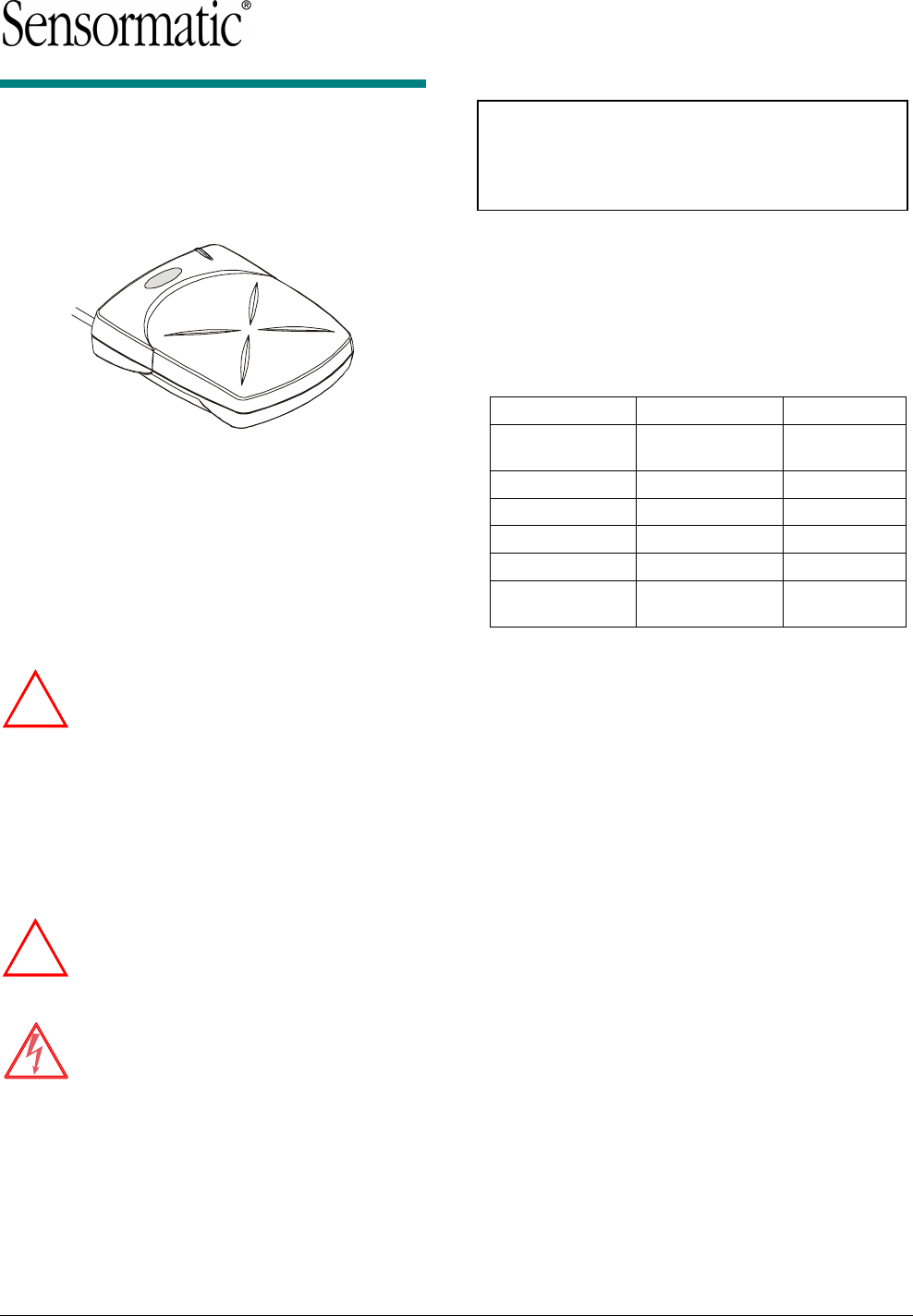
ZBAMB2010T
Tabletop Deactivator
Installation Guide
The AMB-2010 tabletop deactivator consists of the
deactivator unit and a class 2 external power
supply that plugs into an ac outlet. The power LED
glows green when power is applied.
The deactivator deactivates UltraStrip II and III
security labels rubbed and swirled on its surface.
The deactivate field is 10cm (4 in.) square and
7.5cm (3 in.) high. Deactivation is indicated by the
power LED pulsing orange and a long beep.
WARNING: Do not deactivate labels on
audio or videotapes. The deactivate field
is not magnetic media safe.
The deactivator is intended to be installed “as is”
without adjustments. If adjustments are necessary,
a laptop computer containing special configuration
software can be connected to a jack at the rear of
the deactivator.
Please observe the following safeguards before
you begin installation.
WARNING: Hazardous areas.
DO NOT install the deactivator where
highly combustible or explosive products
are stored or used.
WARNING: RISK OF ELECTRIC
SHOCK!
Deactivator has no user-serviceable
parts! DO NOT attempt to open the
deactivator.
Power Cord. The cord cannot interfere
with the operation of cash drawers,
conveyor belts, or with the operation,
maintenance or removal of equipment.
© Sensormatic 2002
If you need assistance…
Call 1-800-241-6678
(Sensormatic / ADT Customer Response Center).
Cleaning the Deactivator
Clean exterior surface using a soft cloth moistened
with warm, soapy water. Dry thoroughly. DO NOT
use solvents or scouring cleanser.
Deactivation Status Indications
Status LED Tone
Power On
Sequence
Flashing Green
(for 10 seconds)
Short Beep
Ready Green
Deactivate Pulsing Orange Long Beep
Transmit Off Flashing Green
Fault Condition Red
Hard Tag
Present
Continuous
Short Beep
Install Kit Required
Install Kit 0352-0101-01
Deactivator Assy. 1 0303-0038-01
Template, Cutout 1 8000-2699-02
Velcro, Hook, w/Adhesive .5ft 3200-0358-01
Velcro, Loop, w/Adhesive .5ft 3200-0358-02
Cable Tie, 5-1/2"L x 16"W, Nylon 3 6009-0001
Mount, Adhesive Backed, 1-1/8 sq. 3 6009-0003
Clamp, Cable, Nylon, .313D, .172MTG 2 6010-0035-10
Screw, Self-Tapping, 3.5x16 PHP 2 5810-3051-120
Label, Keep Magnetic Media Away 1 2402-1301-01
Pad, Alcohol 2 1600-0033
Tools Required
§ Power drill and drill bits
§ Phillips screwdriver
§ Hand vacuum and broom.
Proper Placement
§ DO NOT install the deactivator over a metal
surface. Deactivator fields interact with metal
causing deactivator performance to degrade.
§ The field from the deactivator can interact with
certain POS equipment. Avoid placing the
deactivator too close to POS equipment.
!
!
ZBAMB2010T TABLETOP DEACTIVATOR INSTALLATION GUIDE (8200-0185-01, REV. A)
2 of 3
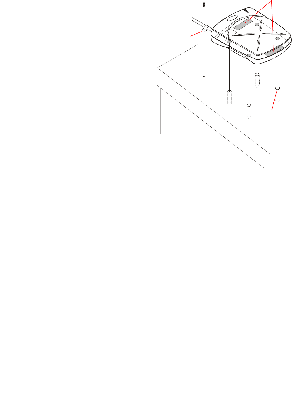
Installation
Positioning the deactivator so the LED window
faces away from the sales associate:
1. Mount the deactivator to the countertop.
Using a ZPCM mounting bracket (optional):
See instructions supplied with bracket.
Using hook and loop material:
a. Mate hook and loop material, then cut
hook and loop material into two strips.
b. Remove the liner from the hook side of
each strip, then fasten a strip to the flat
area on the bottom front and rear edges of
the deactivator.
c. Place the deactivator in the desired
location and press down.
Using M5 machine screws:
a. Place the template supplied in the desired
mounting location and use it to drill four
holes for M5 machine screws.
b. Select the appropriate length for the
screws. Screw length should be 8mm
(.31 in.) plus the counter thickness.
c. From the underside of the countertop,
insert the four machine screws, mate them
with the mounting holes in the bottom of
the deactivator, and tighten from below.
2. Secure the power cable.
Using cable ties (not shown):
a. Remove the liner from the adhesive-
backed mount and run a tie through the
hole in the mount and around the cable.
b. Fasten the cable tie securely around the
cable and remove excess.
Using the cable clamp:
a. Place the clamp around the cable near the
antenna.
b. Secure the clamp in place using a screw.
3. Connect the deactivator to the power supply
and plug the power supply into an ac outlet.
The deactivator will produce a brief tone at
power up.
Cable Clamp,
if used.
Hook and
Loop Material,
if used.
Holes for M5
Machine Screws
(4), if used.

ZBAMB2010T TABLETOP DEACTIVATOR INSTALLATION GUIDE (8200-0185-01, REV. A)
3 of 3
Optional Adjustments
To be determined.
Specifications
Power Supply
Input voltage ..................... 100–240 Vac, 50/60 Hz
AC line current .................. 1 Arms (max.)
Deactivator
Input voltage ..................... 18 Vdc
Auto synchronization......... Optional
Tone volume ..................... Adjustable, Off
Operating temperature......0° to 40°C
Humidity............................ 0 to 90% non-condensing
Weight (deactivator)..........0.95kg (2.1 lbs)
Weight (power supply) ......0.28kg (0.6 lbs)
Declarations
Regulatory Compliance
EMC ....................................... 47 CFR Part 15
RSS 210
EN 300330
EN 301489
EMF........................................ VDE 0848
Safety ..................................... UL60950
EN 60 950
CE Mark
FCC COMPLIANCE: This equipment complies with Part 15
of the FCC rules for intentional radiators and Class A digital
devices when installed and used in accordance with the
instruction manual. Following these rules provides reasonable
protection against harmful interference from equipment
operated in a commercial area. This equipment should not be
installed in a residential area as it can radiate radio frequency
energy that could interfere with radio communications, a
situation the user would have to fix at their own expense.
EQUIPMENT MODIFICATION CAUTION: Equipment
changes or modifications not expressly approved by
Sensormatic Electronics Corporation, the party responsible for
FCC compliance, could void the user's authority to operate the
equipment and could create a hazardous condition.
Other Declarations
WARRANTY DISCLAIMER: Sensormatic Electronics
Corporation makes no representation or warranty with respect
to the contents hereof and specifically disclaims any implied
warranties of merchantability or fitness for any particular
purpose. Further, Sensormatic Electronics Corporation
reserves the right to revise this publication and make changes
from time to time in the content hereof without obligation of
Sensormatic Electronics Corporation to notify any person of
such revision or changes.
LIMITED RIGHTS NOTICE: For units of the Department
of Defense, all documentation and manuals were developed at
private expense and no part of it was developed using
Government Funds. The restrictions governing the use and
disclosure of technical data marked with this legend are set
forth in the definition of “limited rights” in paragraph (a) (15)
of the clause of DFARS 252.227.7013. Unpublished - rights
reserved under the Copyright Laws of the United States.
TRADEMARK NOTICE: Sensormatic, and the Sensormatic
logo are trademarks or registered trademarks of Sensormatic
Electronics Corporation. Other product names mentioned
herein may be trademarks or registered trademarks of
Sensormatic or other companies.
No part of this guide may be reproduced in any form without
written permission from Sensormatic Electronics Corporation.
MDR 11/02