Tyco Safety Sensormatic DEACSLNK Anti-Theft Auxiliary Device User Manual Exhibit 11 Set Up Guide
Tyco Safety Products/Sensormatic Anti-Theft Auxiliary Device Exhibit 11 Set Up Guide
users manual
Preliminary
AMC-4010 SYNCHRONIZATION MODULE INSTALLATION AND SERVICE GUIDE (8200-0183-01, REV. 03)
1 of 5
ZPSYNC4010 Wireless ZPSYNC4010 Wireless
Sychronization Sychronization
ModulesModules
Setup GuideSetup Guide
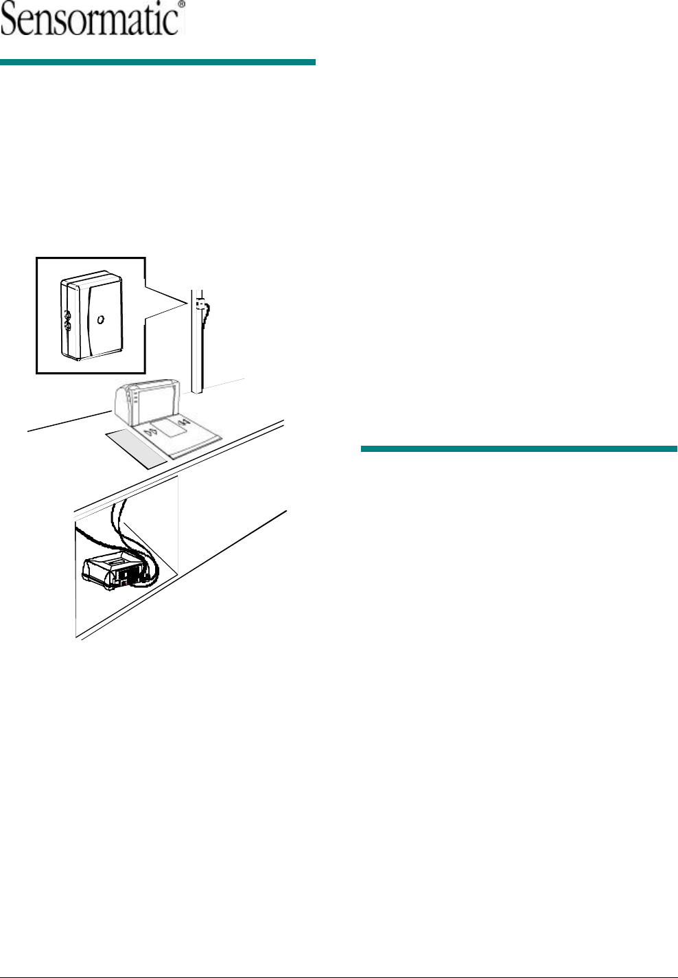
Wireless synchronization modules can significantly
reduce electrical interference between Sensormatic
EAS systems timed to the AC line. A module
system includes a module designated as a
transmitter and one or more modules designated
as receivers.
IMPORTANT! Ensure EAS devices can support
wireless synchronization.
IMPORTANT! The maximum distance between the
transmit module and any receive module is
approximately 60.1m (200 feet), but keep in mind
that the range depends upon the environment in
which the module is used. Many factors can limit
the range, thus it would be impossible to list them.
© Sensormatic 2002
For best performance, please follow these
instructions carefully.
Parts SuppliedParts Supplied
Sync Link Module 1 0304-0029-01
Cable Ties 3 ?
Cable 1 ?
Mechanical SpecificationsMechanical Specifications
Dimensions: 82mm (L) x 60mm (W) x 30mm (D)
Weight: 2.5 oz
Transmit FrequenciesTransmit Frequencies
North America Frequency Hop: 903.2–914.8 MHz
Europe Single Low frequency: 869.8 MHz
Europe Single High frequency: 869.9 MHz
Setting Up the TransmitterSetting Up the Transmitter
1. Find the EAS device that is central and within
60.1m (200 feet) of the others. Designate this
device for use with the transmit module.
IMPORTANT! DO NOT designate a mobile
checkout stand or use with the transmit
module. Only receive modules can be used
with mobile checkout stands.
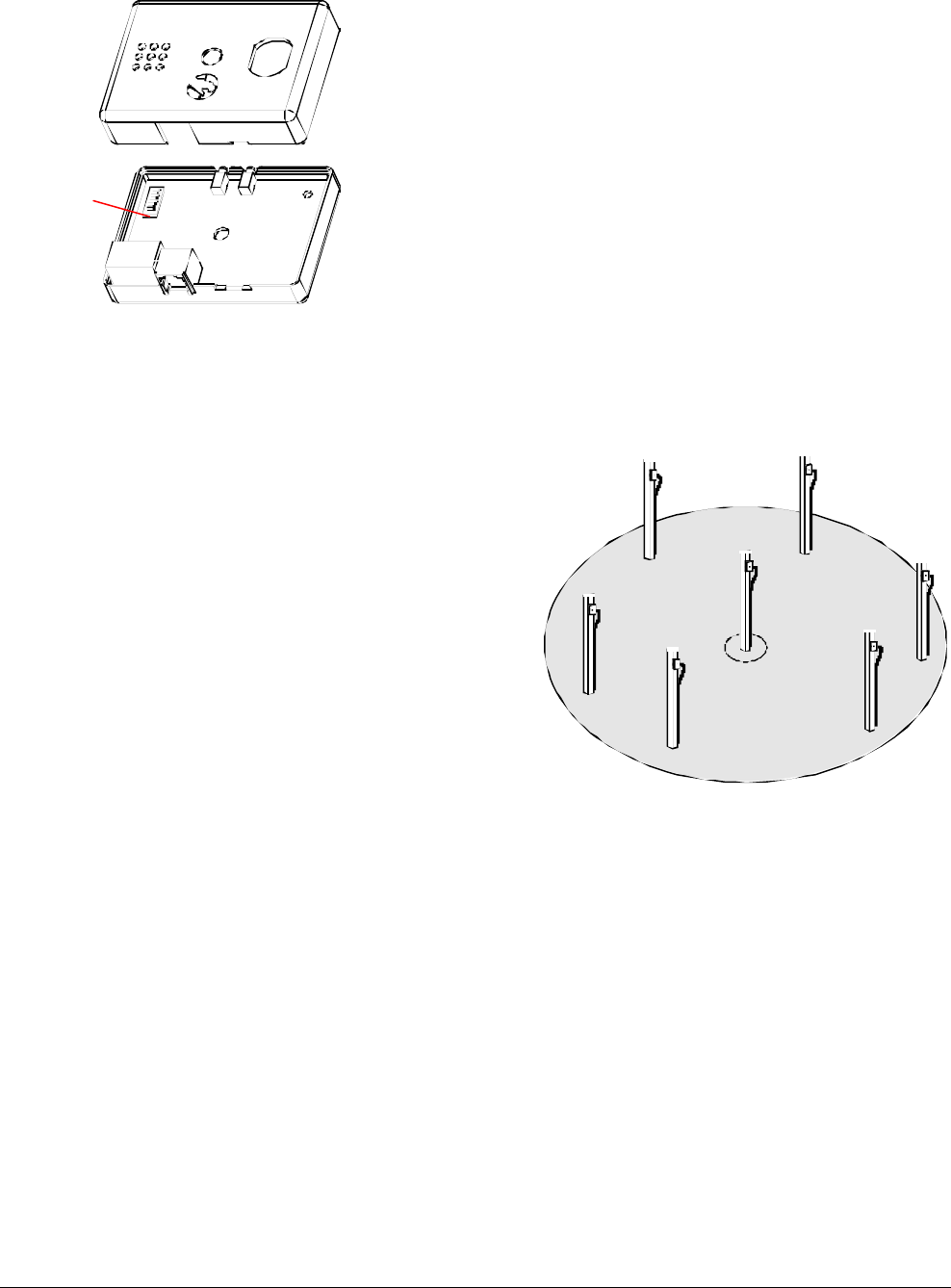
2. Configure one module as the transmitter by
opening it and setting switch 7 to OFF (see
Table on page 3). To access the switch,
remove the holding screw and carefully
separate the top and bottom covers (the side
label serves as a hinge between the two
covers. DO NOT remove this label).
Preliminary
AMC-4010 SYNCHRONIZATION MODULE INSTALLATION AND SERVICE GUIDE (8200-0183-01, REV. 03)
2 of 5
4. Close the module and reattach the holding
screw.
5. Mount the transmit module:
• As high as possible and in a location near
the designated EAS device. The length of
the cable supplied determines the distance
the module can be from the device.
IMPORTANT! Ensure the module will be
within 60.1m (200 feet) of the transmit
module.
• In such a way that the two LEDs on the
module can be readily see from below.
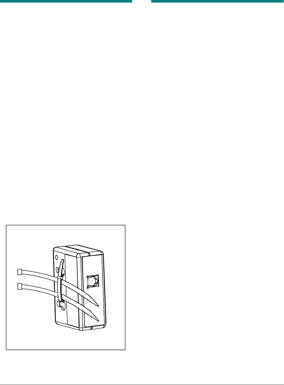
Note: It is recommended to mount the
module to an electrical access pole of a
checkout counter by running a tie wrap
through the two key slots on the back of
the module and then running two additional
tie warps through the tie wrap and around
the pole (see box).
Receivers (Rx) must be within
60.1m (200 feet) of the transmitter (Tx)
6. Using the cable supplied, connect the transmit
module to the expansion port of the EAS
device.
Tx
Rx
Rx
Rx
Rx
Rx
Rx
Switch 7
Preliminary
AMC-4010 SYNCHRONIZATION MODULE INSTALLATION AND SERVICE GUIDE (8200-0183-01, REV. 03)
3 of 5
Setting Up a ReceiverSetting Up a Receiver
1. Mount each receive module:
• As high as possible and in a location near
the designated EAS device. The length of
the cable supplied determines the distance
the module can be from the device.
IMPORTANT! Ensure the module will be
within 60.1m (200 feet) of the transmit
module.
IMPORTANT! If mounting the module to a
mobile checkout stand, mount it on the
stand as high and as far away from
obstructions and metal as possible.
• In such a way that the two LEDs on the
module can be readily see from below.
Note: It is recommended to mount the
module to an electrical access pole of a
checkout counter by running a tie wrap
through the two key slots on the back of
the module and then running two additional
tie warps through the tie wrap and around
the pole (see box).
2. Using the cable supplied, connect the receive
module to the expansion port of the EAS
device.
3. Allow __ time for the modules to synchronize.
Verifying OperationVerifying Operation
Transmit ModuleTransmit Module
Look at the transmit module. The green LED
blinking with the red LED off is normal.
Receiver Module(s)Receiver Module(s)
Look at each receive module. The green LED
glowing steadily with the red LED off is normal.

Preliminary
AMC-4010 SYNCHRONIZATION MODULE INSTALLATION AND SERVICE GUIDE (8200-0183-01, REV. 03)
4 of 5
TroubleshootingTroubleshooting
Transmit ModuleTransmit Module
If the red LED is blinking, this means that the
power line connected to the EAS device it is
connected to has noise on it. Use another EAS
device to drive the transmit module.
ReceivReceive Module(s)e Module(s)
If the red LED is glowing steadily or flickering, this
indicates that the module is either not receiving a
signal from the transmit module or the signal is
weak. Try moving the receiver 15.5 cm (6 inches)
up or down the pole to allow it to receive a stronger
signal.
Mobile checkout stands: If the signal is weak, try
moving the cart closer to the transmit module or
away from obstacles that can block the signal.
Switch settings for transmit or receive setup
DIP Switch Settings
Mode of Operation S1-1 S1-2 S1-3 S1-4 S1-5 S1-6 S1-7 S1-8
RX
60Hz North America
Frequency hop OFF OFF ON ON ON ON ON X
RX
50Hz Europe
Single low frequency ON ON OFF OFF ON ON ON ON
Europe
Single high frequency ON ON OFF OFF ON ON ON OFF
Europe
Single frequency, auto-search OFF ON OFF OFF ON ON ON X
TX
60Hz North America
Frequency hop OFF OFF ON ON ON ON OFF X
TX
50Hz Europe
Single low frequency ON ON OFF OFF ON ON OFF ON
Europe
Single high frequency ON ON OFF OFF ON ON OFF OFF

Preliminary
AMC-4010 SYNCHRONIZATION MODULE INSTALLATION AND SERVICE GUIDE (8200-0183-01, REV. 03)
5 of 5
DeclarationsDeclarations
Regulatory Regulatory ComplianceCompliance
Emissions ........................ 47 CFR, Part 15
RSS 210
EN 300 220
EN 301 489
Safety.............................. UL1950
CSA C22.2 No 950
EN 60 950
FCC COMPLIANCE: This equipment complies with Part 15
of the FCC rules for intentional radiators and Class A digital
devices when installed and used in accordance with the
instruction manual. Following these rules provides reasonable
protection against harmful interference from equipment
operated in a commercial area. This equipment should not be
installed in a residential area as it can radiate radio frequency
energy that could interfere with radio communications, a
situation the user would have to fix at their own expense.
EQUIPMENT MODIFICATION CAUTION: Equipment
changes or modifications not expressly approved by
Sensormatic Electronics Corporation, the party responsible for
FCC compliance, could void the user's authority to operate the
equipment and could create a hazardous condition.
Other DeclarationsOther Declarations
WARRANTY DISCLAIMER: Sensormatic Electronics
Corporation makes no representation or warranty with respect
to the contents hereof and specifically disclaims any implied
warranties of merchantability or fitness for any particular
purpose. Further, Sensormatic Electronics Corporation
reserves the right to revise this publication and make changes
from time to time in the content hereof without obligation of
Sensormatic Electronics Corporation to notify any person of
such revision or changes.
LIMITED RIGHTS NOTICE: For units of the Department
of Defense, all documentation and manuals were developed at
private expense and no part of it was developed using
Government Funds. The restrictions governing the use and
disclosure of technical data marked with this legend are set
forth in the definition of “limited rights” in paragraph (a) (15)
of the clause of DFARS 252.227.7013. Unpublished - rights
reserved under the Copyright Laws of the United States.
TRADEMARK NOTICE: Sensormatic, and the Sensormatic
logo are trademarks or registered trademarks of Sensormatic
Electronics Corporation. Other product names mentioned
herein may be trademarks or registered trademarks of
Sensormatic or other companies.
No part of this guide may be reproduced in any form without
written permission from Sensormatic Electronics Corporation.
MDR 07/02