Tyco Safety Sensormatic DMS915 Digital Microwave System anti-theft equipment User Manual installation and setup ation
Tyco Safety Products/Sensormatic Digital Microwave System anti-theft equipment installation and setup ation
Contents
- 1. installation and setup documentation
- 2. Set up and Installation Guide
- 3. Amended Manual
installation and setup documentation

WORLD LEADER IN ELECTRONIC SECURITY Setup and Service Guide
8000-0395-02, Rev. A (9 pages) MICROWAVE PRODUCTS 1
1 Digital Microwave
System 915
Addendum
EADC12WC DMS Concealed 12'
EADC18WC DMS Concealed 18'
EADC24WC DMS Concealed 24'
EADM06 DMS Micromax 6'
EADM06WCDMS Micromax WC 6'
EADM12 DMS Micromax 12'
EADM12WCDMS Micromax WC 12'
EADM18 DMS Micromax 18'
EADM18WCDMS Micromax WC 18'
EADM24 DMS Micromax 24'
EADP06 DMS Pedestal 6'
EADP18WC DMS Pedestal WC 18'
EADR03WC DMS Sensormat II 3'
EADR06WC DMS Sensormat II 6'
EADR10WC DMS Sensormat II 10'
EADS03 DMS Slimline 3'
EADS06 DMS Slimline 6'
Contents
About this Guide................................................ 1
About the DMS 915........................................... 2
Specifications.................................................... 9
Declarations...................................................... 9
About this Guide
This Setup and Service guide explains typical
installations and tuning for the DMS 915 detector.
It is intended to be used as a supplement to the
DMS 915 Installation and Field Service Manual.
Refer to the DMS 915 manual for a complete
description of theory, installation, and
troubleshooting. Other related documents are:
• DMS 915 Installation and Field Service Manual,
8000-0395-01
Note: Because customer requirements dictate the
placement of detector components, your
Sensormatic representative will supply this
information separately.
If you need assistance...
Call Sensormatic Customer Support at:
1-800-543-9740
Micromax, Sensormatic, and the Sensormatic logo are
registered trademarks of Sensormatic Electronics Corporation.
Other product names (if any) mentioned herein may be
trademarks or registered trademarks of other companies.
No part of this guide may be reproduced in any form without
written permission from Sensormatic Electronics Corporation.
© Copyright 2000. All rights reserved.
(DOJ) 11/00
Preliminary – 11/03/00

2 SETUP AND SERVICE GUIDE DIGITAL MICROWAVE SYSTEM 91
5
8000-0395-02, REV.
A
About the DMS 915
The Digital MicroWave System (DMS) 915 is a
microcontroller-based anti-theft system. The DMS
915 produces an alarm when it detects a
Sensormatic tag, a packaged semiconductor
diode.
To detect the tag, the system performs the
following operations:
• The system generates a “zone of protection,”
typically at a store exit. This zone consists of
two overlapping fields. The first field is a static
or frequency-hopping, frequency modulated
RF signal. The second field is a frequency shift
key (FSK) modulated and predominately
electrostatic field called an E-field.
• When a tag enters the zone, it combines the
RF signal and the E-field into a composite
signal that radiates to the system RF
antennas. The system detects the composite
signal, separates the modulation, and
compares the recovered modulation to the
modulation transmitted. If the two signals
match, the system issues an alarm.
The DMS 915 is programmed using an external
hand-held computer. Programmable features
include RF hopping bank or frequency selection,
RF power level selection, electrostatic field
frequency selection, “tag-too-close” function
enable/disable, alarm tone selection, alarm
duration selection, selectable hits required for
alarm, and alarm count set/reset control.
System Components
DMS 915 components include E-field radiators, RF
antennas, remote alarms, and a programmable
power pack
Three types of E-field radiators are:
• Wire cloth – usually recessed in the floor or
sometimes laid on the floor under a rubber
pad.
• Plate – a metal plate concealed inside a
pedestal at the side of the exit.
• Vortex – a long aluminum bar hung across the
exit.
The RF antennas are used to radiate the
frequency-hopping, frequency-modulated RF
signal. These antennas mount in a variety of ways.
They can be concealed above the ceiling,
mounted in pods, concealed in the floor, or
mounted in pedestal enclosures located at the
store exit.
The remote alarm provides a audio/visual signal
that a tag has entered the “zone of protection.”
The power pack powers and controls the system.
The pack is typically concealed inside an
enclosure.
DIGITAL MICROWAVE SYSTEM 915
8000-0395-02, Rev. A SETUP AND SERVICE GUIDE 3
Typical Installations
DMS 915 components are arranged in various
configurations depending on the application.
Typical installations are:
• Slimline with plates
• Concealed ceramic RF antennas with wire
cloth
• Pedestal with plates
• Pedestal with wire cloth
• Pedestal with vortex
• Micromax plastic RF antenna with vortex
• Micromax plastic RF antenna with wire cloth
• Sensormat II with wire cloth
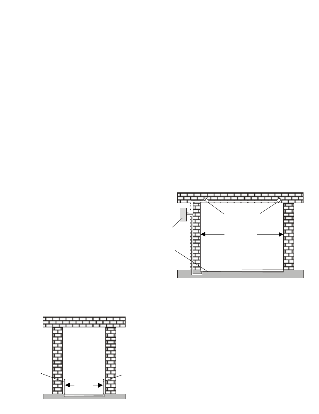
Slimline with Plates
The Slimline with plate system consists of two dish
type RF antennas, each mounted on metal frames
which are enclosed in non-metallic pedestals. A
transmitter/receiver power pack, RF antenna, and
an electrostatic field radiator plate are contained in
one unit while the other pedestal has only an RF
antenna and another electrostatic radiator plate.
The housings are faced toward each other at a
typical distance range from 3 to 6 feet depending
upon the installation. The antennas are connected
to the transmitter/receiver via shielded coaxial
cables.
Components:
• Power Pack
• RF antenna (dish)
• Electrostatic field Slimline plate antenna
• Metal Mounting Frame
• Typical Cosmetic Enclosure – Old
• Typical Cosmetic Enclosure - New
Figure 1. Slimline with plates
Concealed Ceramic RF Antennas with
wire cloth
The Concealed ceramic RF antennas with wire
cloth system consists of two helix type RF
antennas, each resting on the ceiling tiles. The RF
antennas are faced towards each other at a typical
distance range from 3 to 24 feet depending upon
the installation. On the floor between the RF
antennas lays an electrostatic radiator, a wire cloth
whose length is less than the separation between
the RF antennas. The wire cloth is usually
recessed in the floor or sometimes placed on the
floor and covered with a rubber mat. The antennas
are connected to the transmitter/receiver power
pack via shielded coaxial cables. The
transmitter/receiver power pack has an optional
cosmetic enclosure.
Components:
• Power Pack
• RF antenna (helix)
• Electrostatic field wire cloth antenna
• Typical cosmetic mounting enclosure
Figure 2. Concealed antennas with wire cloth
Power pack
RF antenna
Plate antenna
RF antenna
Plate antenna
3-6'
Power
pack
Wire
cloth
RF antenna
3 – 24'
4 SETUP AND SERVICE GUIDE DIGITAL MICROWAVE SYSTEM 91
5
8000-0395-02, REV.
A
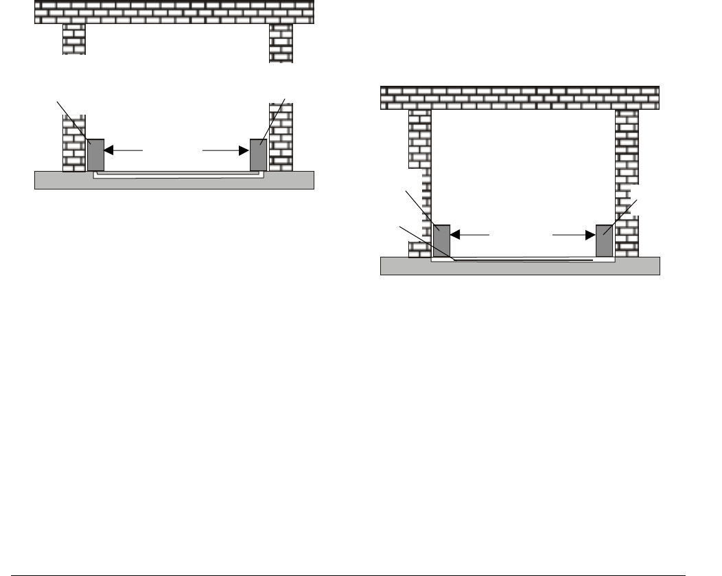
Pedestal with Plates
The Pedestal with plate system consists of two
plastic helix type RF antennas, each mounted and
enclosed in pedestals. A transmitter/ receiver
power pack, RF antenna, and an electrostatic field
radiator plate are contained in one unit while the
other pedestal has only an RF antenna and an
electrostatic field radiator plate. The housings are
faced toward each other at a typical distance
range from 3 to 24 feet depending upon the
installation. The antennas are connected to the
transmitter/receiver via shielded coaxial cables.
Components:
• Power Pack
• RF antenna (helix)
• Electrostatic field plate antenna
• Cosmetic Mounting Enclosure
Figure 3. Pedestal with plates
Pedestal with Wire Cloth
The Pedestal with wire cloth system consists of
two plastic helix type RF antennas, each mounted
and enclosed in pedestals. A transmitter/receiver
power pack and RF antenna are contained in one
unit while the other pedestal has only an RF
antenna. The housings are faced toward each
other at a typical distance range from 3 to 24 feet
depending upon the installation. Between the
housings lays the electrostatic radiator, a wire
cloth antenna at a length less than the pedestal
separation. The wire cloth is usually recessed in
the floor or sometimes laid on the floor and
covered with a rubber mat. The antennas are
connected to the transmitter/receiver power pack
via shielded coaxial cables.
Components:
• Power Pack
• RF antenna (helix)
• Electrostatic field wire cloth antenna
• Rubber Mat
• Cosmetic Mounting Enclosure
Figure 4. Pedestal with wire cloth
Power pack
RF antenna
Plate antenna
RF antenna
Plate antenna
3 – 24'
Power pack
RF antenna
Wire cloth
RF antenna
3 – 24'
DIGITAL MICROWAVE SYSTEM 915
8000-0395-02, Rev. A SETUP AND SERVICE GUIDE 5
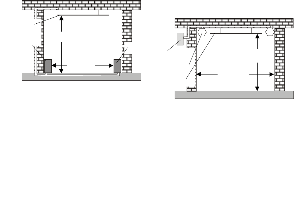
Pedestal with Vortex
The Pedestal with vortex system consists of two
plastic helix type RF antennas, each mounted and
enclosed in pedestals. A transmitter/ receiver
power pack and RF antenna are contained in one
unit while the other pedestal has only an RF
antenna. The housings are faced toward each
other at a typical distance range from 3 to 24 feet
depending upon the installation. In between the
housings is an electrostatic radiator, a vortex bar
antenna which is suspended from the ceiling at an
elevation between 8 and 10 feet. Its length is less
than the pedestal separation. The antennas are
connected to the transmitter/receiver power pack
via shielded coaxial cables.
Components:
• Power Pack
• RF antenna (helix)
• Electrostatic field vortex bar antenna
• Non-metallic Mounting Enclosure
Figure 5. Pedestal with vortex
Micromax Plastic RF Antenna with
Vortex
The Micromax with vortex system consists of two
plastic helix type RF antennas, each mounted and
enclosed in plastic housing pods suspended from
the ceiling or mounted to the floor. The housings
are faced toward each other at a typical distance
range from 3 to 24 feet depending upon the
installation. In between the housings is an
electrostatic radiator, a vortex bar antenna
suspended from the ceiling at an elevation
between 8 and 10 feet. Its length is less than the
Pod separation. The antennas are connected to
the transmitter/receiver power pack via shielded
coaxial cables. The transmitter/receiver power
pack has an optional cosmetic enclosure.
Components:
• Power Pack
• RF antenna (helix)
• RF antenna pod
• Electrostatic field vortex bar antenna
• Typical cosmetic mounting enclosure
Figure 6. Micromax with vortex
V
ortex bar
Power pack
RF
a
n
te
nn
a
RF antenna
3 – 24'
8 – 10'
Power pack
RF antenna
Vortex bar 3 – 24'
8 – 10'
6 SETUP AND SERVICE GUIDE DIGITAL MICROWAVE SYSTEM 91
5
8000-0395-02, REV.
A
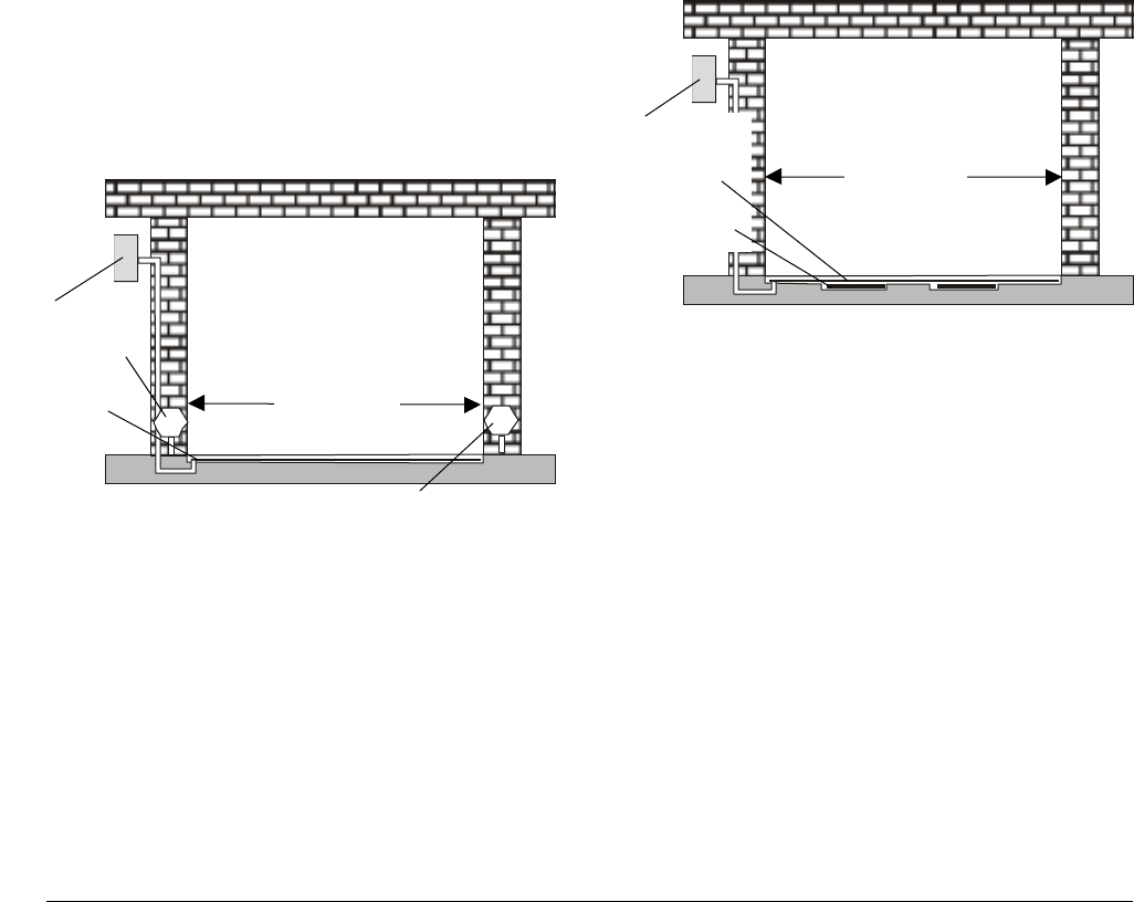
Micromax Plastic RF Antenna with
Wire Cloth
The Micromax with wire cloth system consists of
two plastic helix type RF antennas, each mounted
and enclosed in plastic housing pods suspended
from the ceiling or mounted to the floor. The
housings are faced toward each other at a typical
distance range from 3 to 24 feet depending upon
the installation. In between the housings lays an
electrostatic radiator, a wire cloth antenna whose
length is less than the separation between the
pods. The wire cloth is usually recessed in the
floor or sometimes laid on the surface and covered
with a rubber mat.
The antennas are connected to the
transmitter/receiver power pack via shielded
coaxial cables. The transmitter/receiver power
pack has an optional cosmetic enclosure.
Components:
• Power Pack
• RF antenna (helix)
• RF antenna pod
• Electrostatic field wire cloth antenna
• Typical cosmetic mounting enclosure
Figure 7. Micromax with wire cloth
Sensormat II with wire cloth
The Sensormat II with wire cloth system consists
of two patch RF antennas and an electrostatic field
wire cloth antenna. The patch antennas are placed
on one side of the wire cloth at a typical distance
of 4 feet. The Sensormat II physically covers a
typical exit path from 3 to 10 feet wide, depending
upon the installation. The wire cloth and the patch
antennas are recessed in the floor. The antennas
are connected to the transmitter/ receiver power
pack via shielded coaxial cables. The transmitter/
receiver power pack has an optional cosmetic
enclosure.
Components:
• Power Pack
• RF patch antenna
• Electrostatic field wire cloth antenna
• Typical cosmetic mounting enclosure
Figure 8. Sensormat II with wire cloth
Formica laminated particle board is currently used
to assemble the non-metallic and cosmetic
mounting enclosures referred to above.
Enclosures could be constructed of similar
materials, i.e. plastic, fiberglass, etc. without
affecting the generated fields. The materials used
and the enclosure dimensions may vary for
custom installations.
Power pack
RF antenna
Wire cloth 3 – 24'
Power pack
Wire cloth
RF antenna
3 – 10'
Antenna 3" max from
glass display window

DIGITAL MICROWAVE SYSTEM 915
8000-0395-02, Rev. A SETUP AND SERVICE GUIDE 7
Specifications
Electrical
AC Step-down Transformer
Primary Input: ...................100, 120, or 230Vac,
50/60Hz
Fused Secondary Output: ..24Vac, 50VA, 2.08A
Fuse:................................2.5A LKB STD fast-
blow
DC Power Supply
Resettable Polyswitch:.......3.0A at 20°C (derates
to 2.1A at 50°C)
Positive Regular Outputs: ..+15.8, +12, +8, +5Vdc
Negative Regular Outputs:.-16, -12Vdc
Rated Current (w/o alarm) .<1.5A at 20°C with RF
frequency at 915MHz;
E-field at 500Vp-p,
111.5kHz, 11,000pF
load
Rated Current (with alarm).<2.0A at 20°C with RF
frequency at 915MHz;
RF power at level 10,
E-field at 500Vp-p,
111.5kHz, 11,000pF
load; alarm volume at
maximum
RF Antenna
Dual Helix, Dual patch, Micro II dish
RF Cable
RG142, RG142 B/U 50 ohm
E-Field Generator
Modulated Input Frequency: 442 – 450kHz in
2kHz increments
Modulated Output Frequency: 111.5 – 112.5kHz
in 500Hz increments
Modulation:.......................FSK, 650 – 950Hz
Output Voltage:.................1000Vp-p maximum at
minimum capacitance;
500V maximum at
maximum capacitance
Resonance Range:............Continuous
capacitance, 50pF –
11,000pF
IF FM Detector
Center Frequency: ............111.5kHz
IF Bandwidth (module): .....±4.38kHz maximum
Modulation Frequency Generator: 650 –
950Hz
Transmitter
RF Synthesizer Frequency Range: 888 –
920.1MHz (U.S. range:
902 – 928MHz)
RF Stability (RFS):............RFS <±25ppm
F(TX) = 888MHz,
±22.200kHz
F(TX) = 905MHz,
±22.625kHz
F(TX) = 920.1MHz,
±23.003kHz
RF Bandpass Filter 3dB Bandwidth: 890 –
915MHz
US RF Frequency: ............Voluntary restricted to
902.7 – 904.9MHz
RF Output Power Maximum: +21dBm/port
Power Difference: .............0.5dB maximum
between 902.7MHz –
904.9MHz
Frequency Hopping Mode:.(Complies with FCC
Part 15.247)
Selectable RF Banks:2
Frequency Modulation:......Mod. Freq. = 1.2kHz
Adjacent RF Channel Spacing: 30kHz
RF Channels per RF Bank: >50
RF Hopping Channel:........30kHz minimum
RF Channel Selection:.......Determines by
pseudorandom code
sequence
Output Filter 3dB DW: .......888 – 915MHz
RF Receiver
RF Bandpass Filter 3dB Bandwidth: 890 – 915
MHz
IF Bandwidth:....................BW < or = ±3.5kHz
Input Filter 3dB BW:..........888 - 915MHz
Sensitivity:........................= .1257microVrms
Environmental
Operating Temperature: ....-10 to 50°C (14°–
122°F)

8 SETUP AND SERVICE GUIDE DIGITAL MICROWAVE SYSTEM 91
5
8000-0395-02, REV.
A
Relative Humidity: .............0 to 90% non-
condensing
Mechanical
Power Pack
Length..............................24")
Width................................9.25")
Depth ...............................1.75"
Weight..............................4.6kg (10.2 lbs)
RF Antenna (Dish)
Length..............................1.4"
Diameter...........................7.8"
Weight..............................xkg (x lbs)
RF Antenna (Helix)
Length..............................12 5/8"
Width................................6"
Depth ...............................6"
Weight..............................xkg (x lbs)
RF Antenna (Patch)
Length..............................11 1/8"
Width................................5 7/8"
Depth ...............................0.25"
Weight..............................xkg (x lbs)
Slimline Antenna
Length..............................8"
Width................................6"
Depth ...............................1/16"
Weight..............................xkg (x lbs)
Plate Antenna
Length..............................19.9"
Width................................8.8"
Depth ...............................0.25"
Weight..............................xkg (x lbs)
Wire Cloth Antenna
Length..............................varies
Width................................3.5"
Depth ...............................1/8"
Weight..............................xkg (x lbs)
Vortex Bar
Length..............................varies
Width................................2"
Depth...............................0.5"
Weight..............................xkg (x lbs)
Metal Mounting Frame
Length..............................46"
Width................................10.25"
Depth...............................1.75"
Weight..............................xkg (x lbs)
Cosmetic Enclosure (Old)
Length..............................46.5"
Width................................18.25"
Depth...............................2 7/8"
Weight..............................xkg (x lbs)
Cosmetic Enclosure (New)
Length..............................46.5"
Width................................12"
Depth...............................2 7/8"
Weight..............................xkg (x lbs)
Cosmetic Enclosure (Typical)
Length..............................41.75"
Width................................12.75-17"
Depth...............................12.25"
Weight..............................xkg (x lbs)
Non-metallic Enclosure
Length..............................41.75"
Width................................12.75-17"
Depth...............................12.25"
Weight..............................xkg (x lbs)
Rubber Mat
Length..............................varies
Width................................14"
Depth...............................0.25"
Weight..............................xkg (x lbs)
RF Antenna Pod
Length..............................15.5"
Width................................7.25"

DIGITAL MICROWAVE SYSTEM 915
8000-0395-02, Rev. A SETUP AND SERVICE GUIDE 9
Depth ...............................7.24"
Weight..............................xkg (x lbs) Declarations
Regulatory Compliance
EMC:.............................. 47 CFR, Part 15
Safety: ........................... UL1950 (UL)
Can/CSA C22.2 No.
950
EN60950 (CE)
FCC COMPLIANCE: This equipment complies with Part
15 of the FCC rules for intentional radiators and Class A
digital devices when installed and used in accordance with the
instruction manual. Following these rules provides reasonable
protection against harmful interference from equipment
operated in a commercial area. This equipment should not be
installed in a residential area as it can radiate radio frequency
energy that could interfere with radio communications, a
situation the user would have to fix at their own expense.
EQUIPMENT MODIFICATION CAUTION: Equipment
changes or modifications not expressly approved by
Sensormatic Electronics Corporation, the party responsible for
FCC compliance, could void the user's authority to operate the
equipment and could create a hazardous condition.
Other Declarations
WARRANTY DISCLAIMER: Sensormatic Electronics
Corporation makes no representation or warranty with respect
to the contents hereof and specifically disclaims any implied
warranties of merchantability or fitness for any particular
purpose. Further, Sensormatic Electronics Corporation
reserves the right to revise this publication and make changes
from time to time in the content hereof without obligation of
Sensormatic Electronics Corporation to notify any person of
such revision or changes.
LIMITED RIGHTS NOTICE: For units of the Department
of Defense, all documentation and manuals were developed at
private expense and no part of it was developed using
Government Funds. The restrictions governing the use and
disclosure of technical data marked with this legend are set
forth in the definition of "limited rights" in paragraph (a) (15)
of the clause of DFARS 252.227.7013. Unpublished - rights
reserved under the Copyright Laws of the United States.