Tyco Safety Sensormatic IDX9000 PART 15.247 SPREAD SPECTRUM TRANSMITTER, RFID READER User Manual
Tyco Safety Products/Sensormatic PART 15.247 SPREAD SPECTRUM TRANSMITTER, RFID READER Users Manual
Users Manual
IDX-9000
User Guide
Introduction
This users guide provides overview information for the IDX-9000; which includes models
IDX-9000-US, IDX-9000-EU, IDX-9000-JP, with corresponding part numbers 34000774-
0005, 34000774-1005, 34000774-2005, respectively for the US, EU, and Japan. The IDX-9000
Users Guide includes LED definitions, port descriptions, connection and mounting information,
as well as regulatory and compliance information. References to IDX-9000 apply to all
versions, except where the version is explicitly identified.
This device received all regulatory approvals under the name Sensormatic Electronics. Vue
Technology is the RFID business unit of Sensormatic Electronics.
LED Definitions
See the top view illustration below for the LED positions on the IDX-9000.
LED
State
Description
Error
Off
Flashing
No known error conditions.
Flashes when the power on cycle is initiated. If flashing after
initial power on cycle, the unit has detected errors during self-
test. If errors are detected, contact Technical Support.
RF
On
Off
RF transmitter is turned on and transmitting.
No RF output.
Tag
On
Off
Valid tag(s) are found and being read.
Tags are not currently being read.
Power
On
Off
Flashing
Power is on and unit is ready.
No power to the unit.
Unit is powering on.
All LEDs are off when the power is not connected. All LEDs will be on briefly and cycle
their display when the power is reset. The Green, Yellow1, and Yellow2 LEDs will cycle
when in a downloading state.
Mounting
Position the IDX-9000 on the wall or shelf, ensuring a minimum clearance of five inches
on all sides. Mark the hole locations using the mounting tabs as a guide. The distance
between mounting holes across the width of the connector panels is 200 mm. The
distance between mounting holes across the length of the unit is 226 mm.
Remove the IDX-9000 and drill four mounting holes at the marked locations. Reposition
the IDX-9000 over the mounting holes and secure using fasteners appropriate for its 3.5-
pound weight, the mounting surface, and any other conditions present, such as vibration.
226 mm
200 mm
Power
Tag
RF
Error
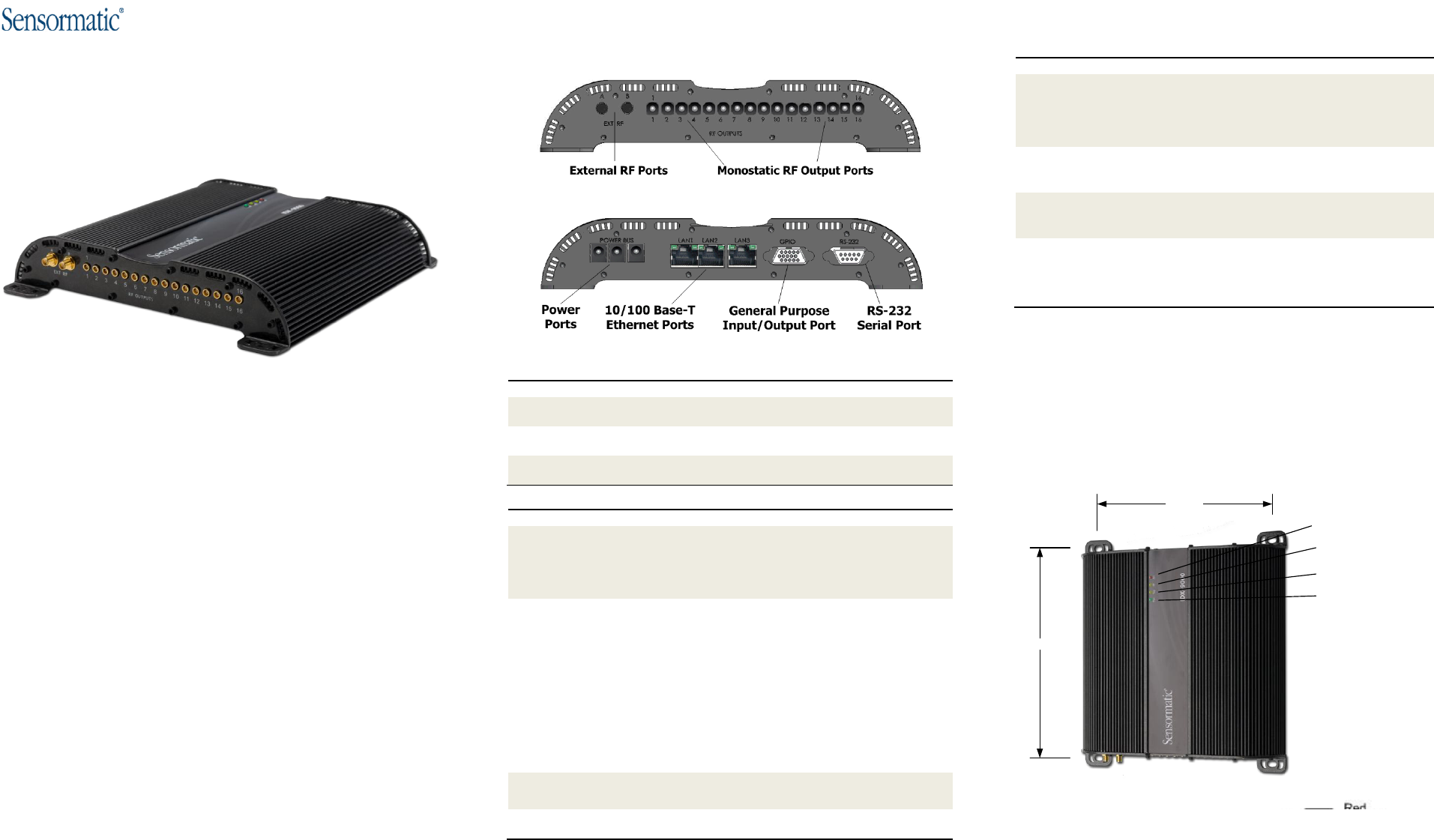
Physical Connections
The physical connections to the IDX-9000 device are shown in the graphics below
RF Side Ports
Digital Side Ports
RF Side Port
Description
EXT RF A
External RF Port A (Reverse SMA)
EXT RF B
External RF Port B (Reverse SMA)
RF Outputs 1-16
Monostatic RF Output Ports (MCX)
Digital Side Port
Description
Power BUS 1-3
Power supply port. Connect the Sensormatic approved power
supply to any of the three ports. The power supply uses an AC
adapter that varies, depending on the country.
Maximum power consumption: 24 VDC, 1.33A.
LAN1
LAN2
LAN3
10/100 Base-T Ethernet Port.
Insert a standard RJ45 Ethernet cable for connection to an Ethernet
network. Insert a cross-connect Ethernet cable for connection to a
local PC.
The left LED indicates link/activities. The LED turns on when the
link is established and flashes when data packets are sent or
received.
The right LED indicates speed. When the left LED is on, the right
LED turns on when the port is linked at 100 Mbps and turns off
when the port is linked at 10 Mbps.
GPIO
General Purpose Input/Output (15 pin) Port. Insert a DE15 cable
assembly for connection to an external device.
RS-232 Serial Port
For serial device connection.

Regulatory Information
All Sensormatic devices are designed to be compliant with rules and regulations in locations in
which they are sold and are labeled, as required. Any changes or modifications to Sensormatic
equipment, not expressly approved, in writing, by Sensormatic could void the authority to
operate the equipment.
Country Approvals
Regulatory markings are applied to the device signifying the radio(s) are approved for use in the
following countries: United States, and Canada,.
Health and Safety Recommendations
Operation of the device without regulatory approval is illegal.
Warning for Use of Wireless Devices
Please observe all warning notices with regard to usage of wireless devices.
Potentially Hazardous Atmospheres
You are reminded of the need to observe restrictions on the use of radio devices in fuel depots.,
chemical plants, etc., and areas where the air contains chemicals or particles (such as grain, dust,
or metal powders) and any other area where you would normally be advised to turn off your
vehicle engine.
Safety in Hospitals
Wireless devices transmit radio frequency energy and may affect medical electrical equipment.
When installed adjacent to other equipment, it is advised to verify that the adjacent equipment is
not adversely effected.
Hearing Aids
The wireless device may interfere with some hearing aids. In the event of interference, you
may want to consult your hearing aid supplier to discuss solutions.
Other Medical Devices
Please consult your physician or the manufacturer of the medical device to determine if the
operation of your wireless product may interfere with medical devices.
Remote and Standalone Antenna Configurations
The antennas used with this transmitter must be installed to provide a minimum separation
distance of 25 cm from all persons and must not be co-located or operated in conjunction with
any other antenna or transmitter. End users and installers must be provided with antenna
installation instructions and transmitter operating conditions for satisfying RF exposure
compliance.
Power Supply
Use only the Sensormatic Electronics power supply provided with this unit or other power
supply approved by and obtained from Sensormatic for use with this product.
Wireless Devices - Countries
If frequency is selectable for your model, select only the country in which you are using the
device. Any other selection will make the operation of this device illegal.
Frequency of Operation - FCC and IC (US/Canada Versions)
The unit operates from 902-928 Mhz at a maximum power level of 1W.
Federal Communications Commission (FCC)
This equipment has been tested and found to comply with the limits for a Class B digital device,
pursuant to part 15 of the FCC Rules. These limits are designed to provide reasonable
protection against harmful interference in a residential installation. This equipment generates,
uses, and can radiate radio frequency energy and, if not installed and used in accordance with
the instructions, may cause harmful interference to radio communications. However, there is
no guarantee that interference will not occur in a particular installation. If this equipment does
cause harmful interference to radio or television reception, which can be determined by turning
the equipment off and on, the user is encouraged to try to correct the interference by one or
more of the following measures:
Reorient or relocate the receiving antenna.
Increase the separation between the equipment and receiver.
Connect the equipment into an outlet on a circuit different from that to which
the receiver is connected.
Consult the dealer or an experienced radio/TV technician for help
Operation is subject to the following two conditions: (1) this device may not cause interference,
and (2) this device must accept any interference, including interference that may cause
undesired operation of the device.
This device has received regulatory approval with and been designed to operate only with
Sensormatic Electronics approved antennas. Use of antennas not on Sensormatic’s approved
list will not be supported by Sensormatic Electronics and may damage the device, as well as
violate local regulations.
Canada Industry (IC)
This Class B digital device complies with Canadian ICES-003.
Cet appareil numérique de la classe B est conforme à la norme NMB-003 du Canada.
Radio Transmitters
This device complies with RSS210 of the Industry & Science Canada. Operation is subject to
the following conditions: This device may not cause harmful interference and this device must
accept any interference received, including interference that may cause undesired operation.
Approved Antennas
This device has been designed to operate only with Sensormatic Electronics approved
antennas described in the table below. Antennas not included in this approved list are strictly
prohibited for use with this device.
Manufacturer
Model Number
Polarization
Composite
Gain
Symbol
AN480-CL66100WR
LHCP
6 dBiL
Symbol
AN480-CR66100WR
RHCP
6 dBiL
Sensormatic
IDA-2100
RHCP
6dBiL
Sensormatic
IDA-2400
RHCP
6dBiL
Restriction of Hazardous Substances Directive (RoHS)
All parts and components are manufactured in accordance to and be compliant with the
“DIRECTIVE 2002/95/EC OF THE EUROPEAN PARLIAMENT AND OF THE
COUNCIL of 27 January 2003 on the restriction of the use of certain hazardous substances in
electrical and electronic equipment.
© 2010 Sensormatic Electronics, LLC. All rights reserved.
Sensormatic reserves the right to make changes to any product to improve reliability, function
or design. Sensormatic does not assume any product liability arising out of, or in connection
with, the application or use of any product, circuit, or application described herein. No license
is granted, either expressly or by implication, estoppels, or otherwise under any patent right or
patent covering or relating to any combination, system, apparatus, machine, material, method,
or process in which Sensormatic products might be used. An implied license exists only for
the equipment, circuits, and subsystems contained in Sensormatic products.
Sensormatic and the Sensormatic logo are registered trademarks of Sensormatic Electronics,
LLC . The VUE logo and Vue Technology are trademarks of Sensormatic Electronics, LLC.
All other product names or company names mentioned in this document may be trademarks
or registered trademarks of their respective companies and are hereby acknowledged.
Service
If a problem using the equipment occurs, contact the facility Technical or Systems Support. If
there is a problem with the equipment, they must contact Sensormatic Technical Support at
http://www.sensormatic.com/support/techsupport/default.aspx.
Sensormatic Electronics
6600 Congress Ave. Boca Raton, FL 33431-0837
http://www.sensormatic.com
Part Number: 10000811-0005