Tyco Safety Sensormatic UMEXCAL Anti Theft Device User Manual Exhibit 11 User s s
Tyco Safety Products/Sensormatic Anti Theft Device Exhibit 11 User s s
users manual
Preliminary
AMS-1070 CONTROLLER INSTALLATION GUIDE (8200-0127-06, REV. 0)
1 of 13
AMS-1070 Controller
Installation Guide
ZEDEX-1070
Contents
About this Guide ................................................ 1
About the Product .............................................. 2
Installation Requirements .................................. 2
Installing the Controller ...................................... 4
Connecting the Antennas and Remote Alarm
Module ............................................................... 5
Connecting a tall and a short antenna ........ 5
Connecting two short antennas and a remote
alarm module .............................................. 5
Connecting a split-receiver (dual-aisle)
configuration................................................ 6
Connecting the Noise Canceling Antennas....... 6
Connecting to Relays in the Controller .............. 6
Connecting Power to the Controller................... 7
Connecting a Service Laptop to the Controller.. 7
Connecting a Modem to the Controller.............. 8
Connecting a Controller to an RS-485 Network 9
Connecting a Modem to an RS-485 Network.. 10
Specifications................................................... 10
Declarations..................................................... 13
Regulatory Compliance............................. 13
Other Declarations .................................... 13
© Sensormatic 2002
About this Guide
This installation guide explains how to install the
controller for an AMS-1070 system. This document
only describes how to install the controller and
connect the antenna cables. Information on how to
mount the antennas is in the antenna documents.
Other related documents are:
• Install Guide, AMS-1070 Antenna, P/N 8200-
0127-01
• Quick Install Guide, AMS-1070 Remote Alarm
Module, P/N 8200-0127-02
• Installation Guide, Digital 216 Noise Coils 8000-
2693-05
• Quick Install Guide, AMS-1070 Antenna Flush-
Mount Brackets, P/N 8200-0127-07
• Quick Install Guide, AMS-1070 Antenna
Cantilever-Mount Brackets, P/N 8200-0127-08
• Quick Install Guide, AMS-1070 Antenna Pole-
Mount Brackets, P/N 8200-0127-09
• Installation Guide, AMS-1070 Controller EMI
Shield 8200-0127-12
• Installation Guide, AMS-1070 Controller Under
Counter Installation Guide 8200-0127-13
• Installation Guide, AMS-1070/ScanMax Pro
Deactivator Mounting Plate 8200-0127-14
Note: Because customer requirements dictate the
placement of system components, your
Sensormatic representative will supply this
information separately.
Preliminary
AMS-1070 CONTROLLER INSTALLATION GUIDE (8200-0127-06, REV. 0)
2 of 13
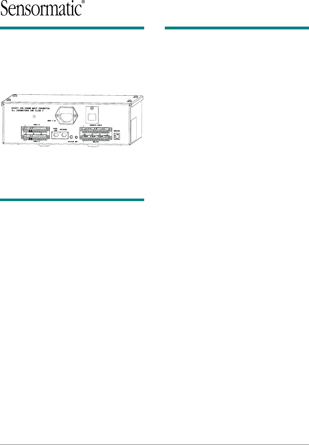
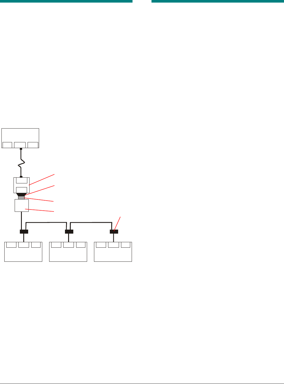
About the Product
An AMS-1070 controller is part of an Ultra•Max®
security label detector. The controller powers and
controls up to four transceiver antennas, two
optional remote alarm modules, and two noise
canceling antenna kits. Figure 1 shows the system
components.
Figure 1. System components
Installation Requirements
Verifying Equipment and Unpacking
❑ Verify that all equipment has arrived. Make sure
the system configuration is the right one for the
installation site.
❑ Unpack major components in a back room. At
the install site, lay out parts in the order you will
need them. Do not clutter the aisle or cause a
trip hazard.
Installer/Contractor
❑ Shall have electrical work comply with the latest
national electrical code, national fire code, and
all applicable local codes and ordinances.
❑ Shall coordinate all work with other trades to
avoid interference.
❑ Shall verify existing site conditions and
coordinate with the owner’s representative and
appropriate utilities as required.
❑ Shall obtain copies of all related plans,
specifications, shop drawings and addenda to
schedule and coordinate related work.
❑ Shall thoroughly review the project to ensure
that all work meets or exceeds the above
requirements. Any alleged discrepancies shall
be brought to the attention of Sensormatic
Electronics.
!WARNING!
Do not install this product in hazardous
areas where highly combustible or
explosive products are stored or used.
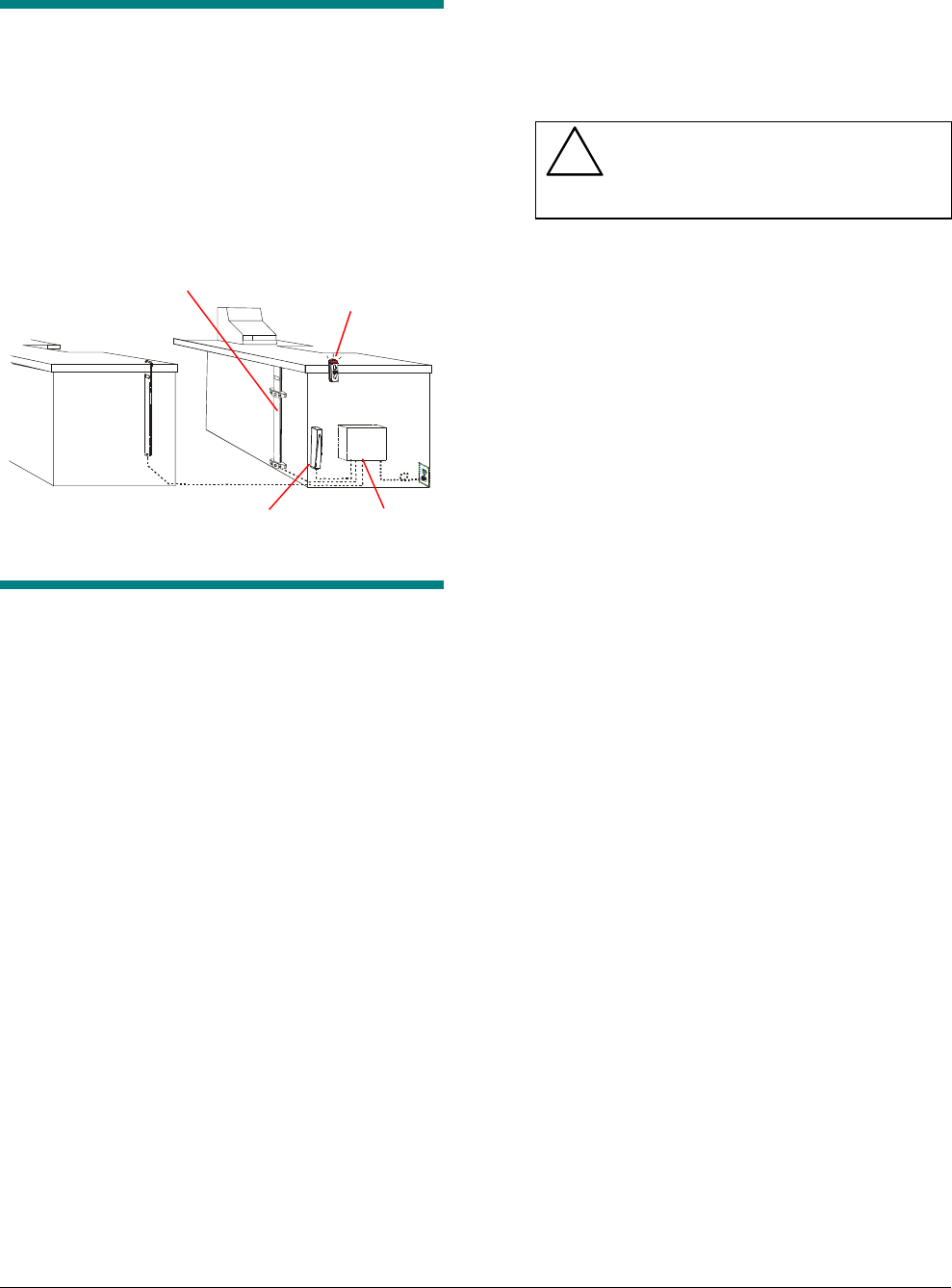
Site Requirements
Refer to Figure 2 for description of site
requirements and placement considerations.
❑ Connect the controller to a 100-240Vac source.
No fuse exchange is required for the controller.
❑ Use the appropriate power cord based on the
country of use.
❑ Replace the controller’s slow-blow fuses only
with a fuse of the same type and rating.
Tools and Equipment Required
For all controller installations:
• Phillips and slotted screwdrivers
• Wire strippers
• Cordless drill and phillips-head screwdriver bits
Ranger
Remote Alarm
Module
Controller
Antenna
Preliminary
AMS-1070 CONTROLLER INSTALLATION GUIDE (8200-0127-06, REV. 0)
3 of 13
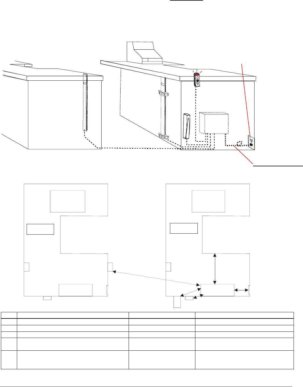
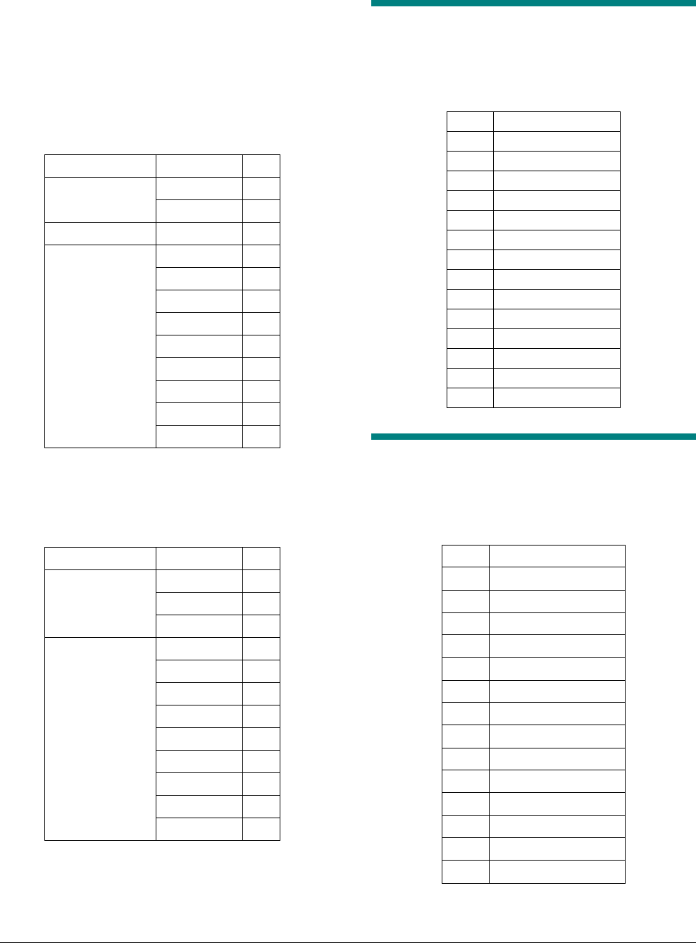
Figure 2. Component placement constraints
Ref Description Distance Reason
[a] Controller to antenna separation 9m (30ft) max Tx/Rx cable length
[b] Controller to ranger separation 12m (40ft) max Ranger cable length
[c] Controller to remote alarm unit separation 9m (30ft) max Remote alarm unit cable length
[d] Controller to power outlet separation 2.3m (7.5’) max (USA)
2.5m (8’) max (non-USA)
Length of power cord
[e] Space around all sides of controller 20cm (8in) min Ventilation. May be mounted on shelf
or wall. May be hidden (e.g. checkout
counter, backroom, basement).
[a]
[b]
[c]
[d]
[e]
Controller
Ranger
Antenna
Power cord options
P/N 0351-0547-0x
-01 USA
-02 Schuko
-03 UK
-04 Japan
-05 USA line filter
-07 Australia
Power Outlet
Voltage Range: 100-240Vac (50-60Hz)
Type: Three-wire, unswitched. Do not use
orange outlets; they are dedicated to
computer equipment).
Availability 24 hours
Grounding: < 0.5Vac between neutral and ground
Loading: Cannot share line with neon signs,
motors, computers, cash registers,
terminals or data communications
equipment.
Power outlet

Preliminary
AMS-1070 CONTROLLER INSTALLATION GUIDE (8200-0127-06, REV. 0)
4 of 13
Installing the Controller
The controller can be mounted on a wall or rest on
a shelf (no mounting procedure required).
• To mount the controller on a wall, proceed
to the section below.
• Otherwise, go to “Connecting the
Antennas and Remote Alarm Module” on
page 5.
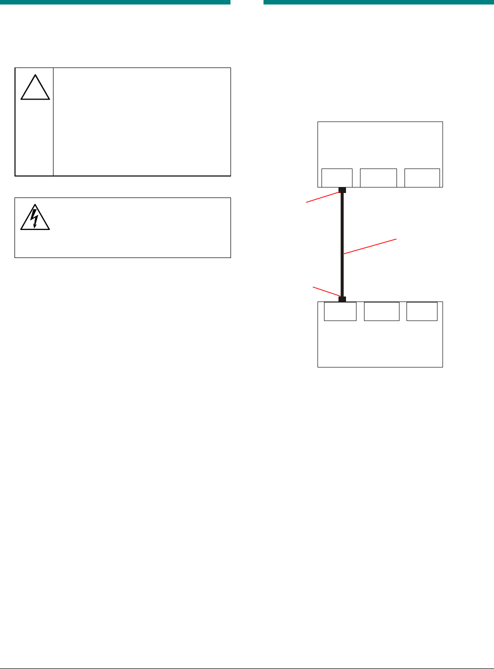
The pack may be mounted in any orientation
except one. Do NOT mount the pack with the
power cord and connectors on top. See Figure 3.
Figure 3. Wall mounting orientations
1. Unscrew the mounting plate from the
bottom of the controller.
2. Select the mounting method.
The mounting method must be able to support
24kg (53 lbs.) if both the controller and the
deactivator are mounted together and 12kg (27
lbs.) if the controller is mounted by itself.
Therefore, the controller should only be
mounted to metal or wood, not to hollow walls.
For wood or metal walls, you can use 10 x 1-
1/2” self-drilling phillips-head screws (P/N 5899-
0031-01).
3. Using a level, position the mounting plate on
the wall and mark the four mounting hole
locations.
4. Attach the mounting plate to the wall with
screws.
Figure 4. Attaching the mounting plate
5. Hang the controller onto the mounting plate
and slide it over to the left until it is secure,
as shown in Figure 5.
Figure 5. Attaching the controller to the
mounting plate
6. If the power pack for a ScanMax Pro
deactivator is nearby, you can use the
ScanMax Pro mounting plate (Figure 6) to
mount the deactivator to the top of the
controller to conserve space.
Refer to the AMS-1070/ScanMax Pro
Deactivator Mounting Plate Installation Guide
(8200-0127-14) for the installation procedure.
Figure 6. ScanMax Pro mounting plate
OK
NO!
O
K
OK
Preliminary
AMS-1070 CONTROLLER INSTALLATION GUIDE (8200-0127-06, REV. 0)
5 of 13
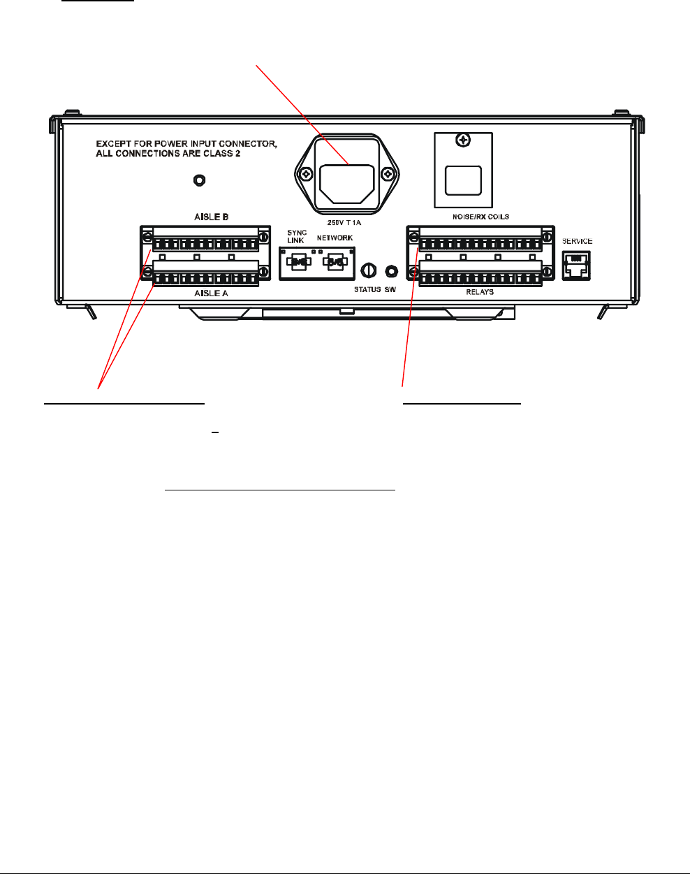
Connecting the Antennas
and Remote Alarm Module
The cables from the antennas and remote alarm
module are inserted into the Aisle A and Aisle B
connectors. Table 1 below lists the signals the
cables carry.
Table 1. Controller Aisle connector pinout
Wire
Color
Signal Description
Red Tx -
Black Tx +
Shield Shield*
Brown Piezo
Orange RS-232 Rx (from pack)
Yellow RS-232 Tx (from pack
Green Lamp 1
Blue Lamp 2
Violet +12V
Gray Digital Ground*
* Never connect shield to Digital Ground
The correct wiring method depends on the antenna
configuration. The following sections describe how
to wire each of the basic antenna configurations
listed in Table 2. A tall antenna is an alarming
antenna; a short antenna is a non-alarming
antenna.
Table 2. Basic antenna configurations
Configuration
Alarming
Antenna
Non-
Alarming
Antenna
Remote
Alarm
Module
Tall/short 1 1 0
Short/short 0 2 1
Regular split 1 2 0
The EMI shields must be put on the antenna and
alarm cables before you connect the wires to the
connectors. Refer to the AMS-1070 EMI Shield
Installation Guide (8200-0127-12) before
proceeding.
Connecting a tall and a short
antenna
If you are connecting an alarming antenna and a
non-alarming antenna to the controller, use Table 3
to connect the antennas.
Table 3. Antenna connector pinout
Cable Wire Color Pin
Red 1
Non-alarming Black 2
Non-alarming and Alarming Shield 3
Black 4
Red 5
Brown 6
Orange 7
Yellow 8
Green 9
Blue 10
Violet 11
Alarming
Gray 12
Connecting two short antennas
and a remote alarm module
If you are connecting two non-alarming antennas
and a remote alarm module to the wiring harness,
use Table 4 to connect the antennas and remote
alarm module.
Table 4. Antenna connector pinout
Cable Wire Color Pin
Red 1
Non-alarming 1 Black 2
Non-alarming 1 and 2 and
remote alarm module
Shield 3
Black 4
Non-alarming 2 Red 5
Brown 6
Orange 7
Yellow 8
Green 9
Blue 10
Violet 11
Remote alarm module
Gray 12
Preliminary
AMS-1070 CONTROLLER INSTALLATION GUIDE (8200-0127-06, REV. 0)
6 of 13
Connecting a split-receiver
(dual-aisle) configuration
If you are connecting two non-alarming antennas
and one alarming antenna to the wiring harness,
use Table 5 and Table 6 to connect the antennas.
Table 5. Aisle A connector
Cable Wire Color Pin
Red 1
Non-alarming 1 Black 2
Both antennas Shield 3
Black 4
Red 5
Brown 6
Orange 7
Yellow 8
Green 9
Blue 10
Violet 11
Alarming
Gray 12
For zone identification to work properly, the
alarming antenna must be installed so the piezo on
it faces non-alarming antenna 1.
Table 6. Aisle B connector
Cable Wire Color Pin
Red 1
Black 2
Non-alarming 2
Shield 3
Black 4
Red 5
Brown 6
Orange 7
Yellow 8
Green 9
Blue 10
Violet 11
Unused
Gray 12
Connecting the Noise
Canceling Antennas
The table below lists the pinouts for the Noise/Rx
Coils connector.
Pin Signal
1 Shield
2 Coil A Return
3 Coil A
4 Coil B Return
5 Coil B
6 Shield
7 Inhibit Aisle A
8 Inhibit Aisle B
9 Digital Ground
10 I/O Port 1
11 I/O Port 2
12 I/O Port 3
13 Digital Ground
14 Shield
Connecting to Relays in the
Controller
The table below lists the pinouts for the Relay
connector.
Pin Signal
1 Relay A Arm
2 Relay A NC
3 Relay A NO
4 Shield
5 Relay B Arm
6 Relay B NC
7 Relay B NO
8 Shield Ground
9 System Error Arm
10 System Error NC
11 System Error NO
12 Shield
13 Shield
14 Shield
Preliminary
AMS-1070 CONTROLLER INSTALLATION GUIDE (8200-0127-06, REV. 0)
7 of 13
Connecting Power to the
Controller
!
For installation using a line cord, the
socket-outlet must be installed near
the equipment and at a location which
is easily accessible.
Für Installationen mit einem
Stromkabel muß die Steckdose an
einem Standort installiert werden,
welcher einfachen Zugang erlaubt.
WARNING—RISK OF ELECTRIC
SHOCK!
The AC power line could be carrying
120Vac or 240Vac.
The AC power source can be 100-240Vac and is
connected by an ac power cord. Attach the
appropriate power cord based on the country of
use.
USA-IEC 320, 18/3, 125V, 10A, 7.5ft. 0351-0547-01
Schuko-IEC 320, 1mm sq., 250V, 10A, 2.5m 0351-0547-02
UK-IEC 320, 1mm sq., 250V, 10A, 2.5m 0351-0547-03
Japan-IEC 320, 2mm sq., 250V, 15A, 2.5m 0351-0547-04
US-Filter, Line, 125V, 6A, Plug-in 0351-0547-05
Australia to IEC 320, 2.5m, 250V, 10A 0351-0547-07
Connecting a Service
Laptop to the Controller
To use the configurator on your service laptop to
configure the controller, connect your laptop to the
Service connector on the controller.
Figure 7. Connecting a laptop to the controller
RS232 Modem
Service Laptop
Ethernet
Sync
Service Network
AMS-1070
Controller
RJ22
male
RJ11
male
RJ11 male to RJ22
male cable
Preliminary
AMS-1070 CONTROLLER INSTALLATION GUIDE (8200-0127-06, REV. 0)
8 of 13
Connecting a Modem to the
Controller
If you are not connecting a modem to the
controller, skip this section.
When a modem is connected to the controller, a
remote computer can dial-up and connect to the
controller for remote service. The following
hardware is required:
• External modem – you must flash the modem
and set the dip switches before using. Refer to
the AMS-1070 Setup and Service Guide for
more information.
• DB25 male to RJ12/RJ11 female connector
• RJ11 male to RJ22 male cable
Figure 8. Connecting a modem to the controller
RS232 Modem
Service Laptop
Ethernet
Sync
Service Network
AMS-1070
Controller
Modem
TO LINE
DB25
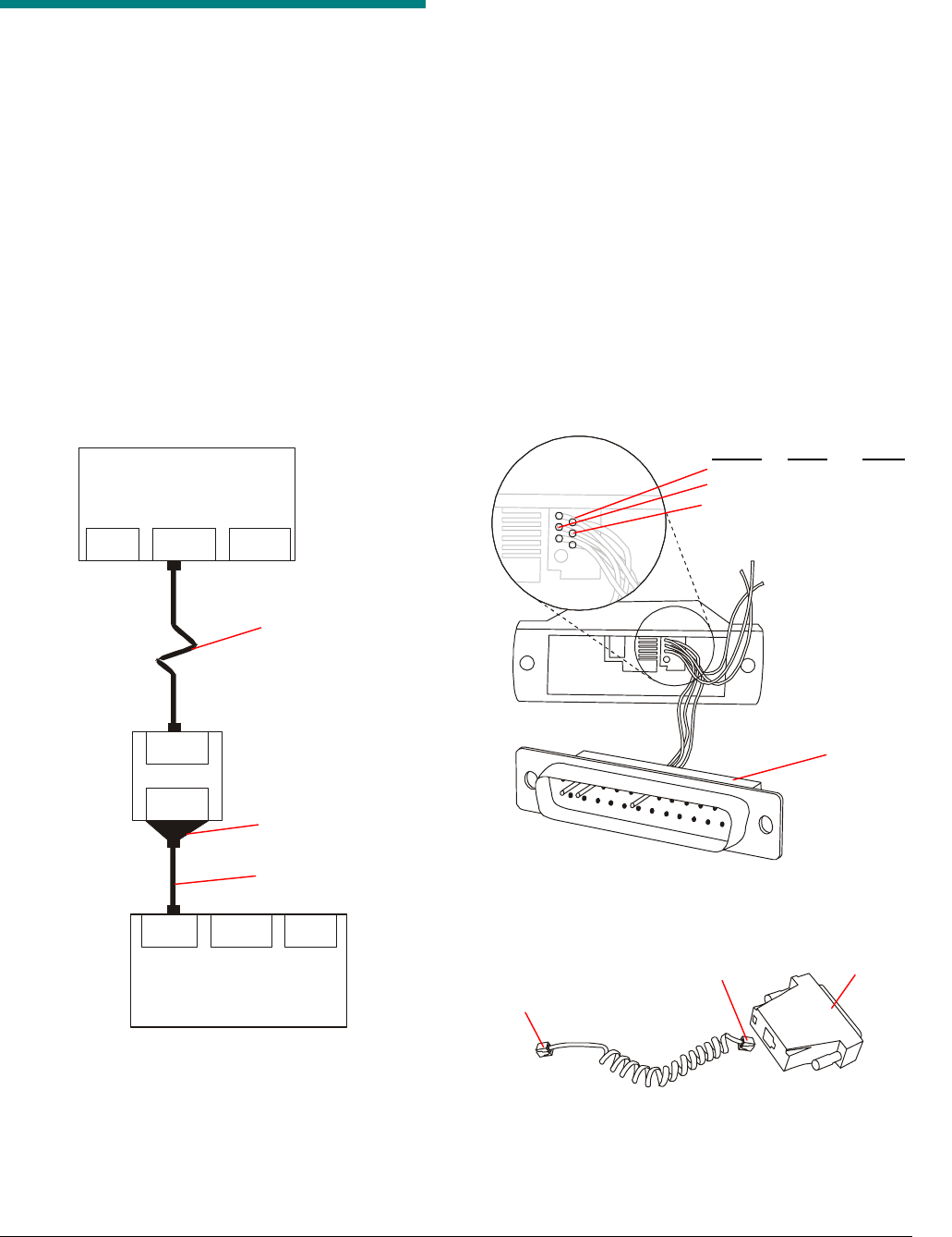
To connect the modem to the controller, do the
following:
1. Prepare the DB25 to RJ12/RJ11 connector.
Follow the diagram in Figure 9.
2. Connect the DB25 connector to the modem.
3. Connect the RJ11 connector to the DB25 to
RJ12/RJ11 connector (Figure 10).
4. Connect the RJ10 connector to the
controller.
5. Connect the telephone line to the TO LINE
port of the modem.
Figure 9. Preparing DB25 to RJ12/RJ11 adapter
1
2
2
34
56
3
7
Figure 10. Modem cabling
Signal RJ12 DB25
Rx Pin 2 Pin 3
Tx Pin 3 Pin 2
Gnd Pin 4 Pin 7
RJ12/RJ11
Inside View
DB25
DB25 (to
Modem)
RJ11
RJ22 (to controller)
DB25 male to
RJ12/11 male
adapter
Telephone line
RJ11 male to RJ22
male cable
Preliminary
AMS-1070 CONTROLLER INSTALLATION GUIDE (8200-0127-06, REV. 0)
9 of 13
!
!
Connecting a Controller to
an RS-485 Network
If you are not connecting the controller to an RS-
485 network, skip this section.
You can network controllers two different ways.
The first way is to use the SyncLink port and the
Network port to daisy-chain the controllers. This
method is shown Figure 11. This method is only
possible, however, if the SyncLink port is not used
for the SyncLink feature.
If the SyncLink port is already in use (or will be in
use), you can network the controllers by
connecting an RJ-12 “T” adapter to the Network
port, as shown in Figure 12.
You can connect a maximum of 32 controllers in an
RS-485 network. More than 32 controllers requires
multiple networks.
The following equipment is required:
• RS232/485 converter – one for every 32
controllers
• RJ-12 connectors – must be 6-wire
• RJ-12 T adapter - available from Black Box
(part number CBCC47289)
• Cabling – you may use either flat telephone
cable or CAT5 cable. Only 3 wires are used.
CAUTION: Do not put the RJ-12
connectors on upside down. Reversing
the order of the conductors will connect
+5V to ground, which will damage the
controller.
CAUTION: Do not connect a Sync-Link
port directly to another Sync-Link port.
Doing so can cause damage to the
controller if one of the controllers is
turned off.
Figure 11. Using the SyncLink and Network
ports to network several controllers
Sync
Service Network
A
MS-1070
Controller
232/485
Converter
Sync
Service Network
AMS-1070
Controller
Sync
Service Network
AMS-1070
Controller
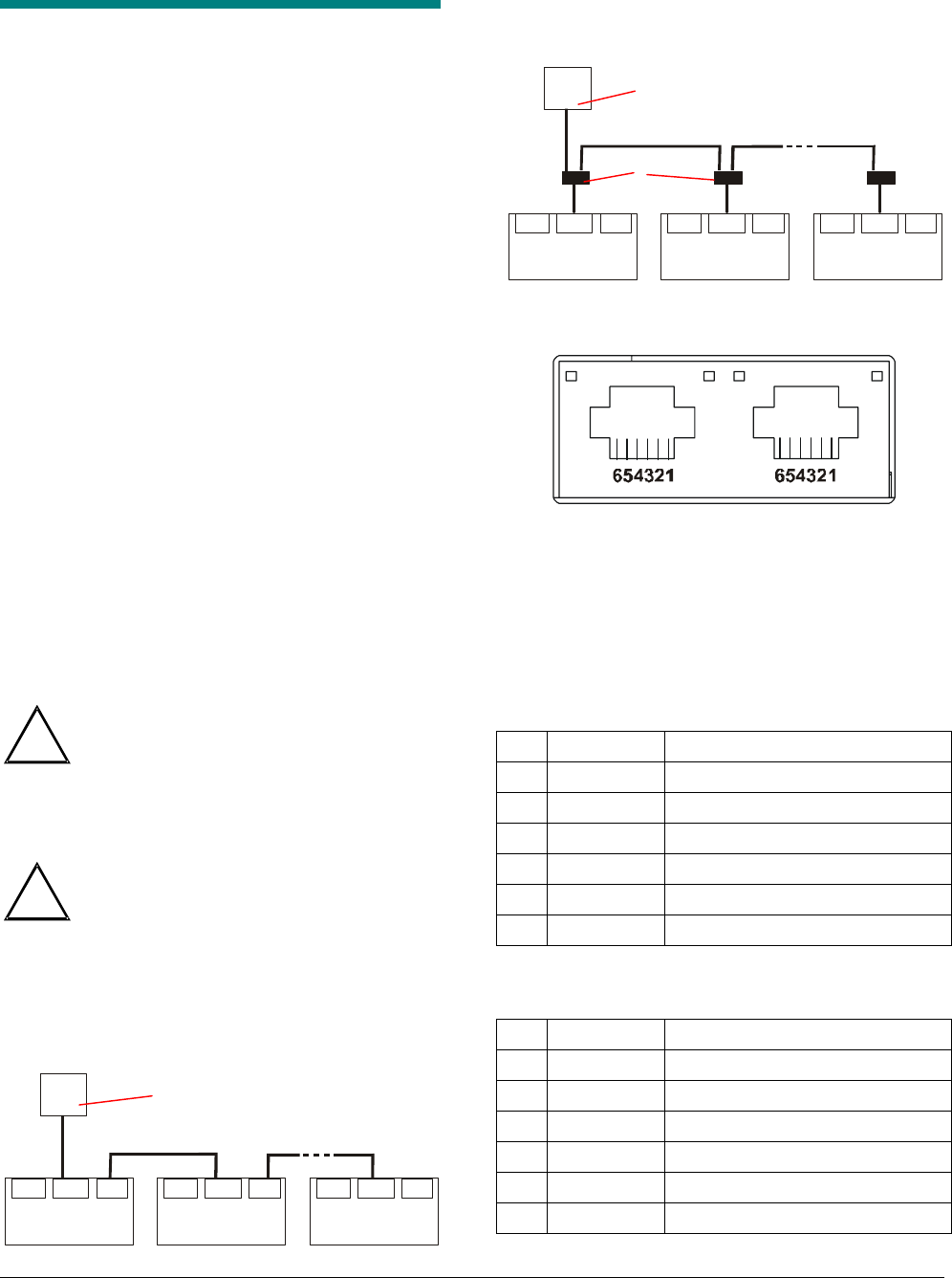
Figure 12. Using an RJ-12 "T" adapter to
network several controllers
Sync
Service Network
A
MS-1070
Controller
232/485
Converter
Sync
Service Network
AMS-1070
Controller
Sync
Service Network
AMS-1070
Controller
Figure 13. SyncLink and Network connectors
Table 7 and Table 8 show the pinouts for the
SyncLink and Network ports. To connect the
controllers in an RS485 network, you must connect
pin 1 of either the SyncLink port (method 1) or the
Network port (method 2) on one controller to pin 1
of the Network port on the next controller. Similarly,
pin 4 must connect to pin 4 and pin 5 to pin 5.
Table 7. Sync Link connector pinout
Pin Signal Description
1 Gnd Digital Ground
2 Synclinkout
3 Synclinkin
4 RS485A Also known as 485-
5 RS485B Also known as 485+
6 +5v Not used
Table 8. Network connector pinout
Pin Signal Description
1 Gnd Digital Ground
2 NC No connect
3 NC No connect
4 RS485A Tied to pin 4 on SyncLink port
5 RS485B Tied to pin 5 on SyncLink port
6 NC No connect
T adapte
r
SYNCLINK NETWORK
RS232/485 converter
RS232/485 converter
1 32
32
1
2
2
Preliminary
AMS-1070 CONTROLLER INSTALLATION GUIDE (8200-0127-06, REV. 0)
10 of 13
Connecting a Modem to an
RS-485 Network
Figure 14 shows a service laptop connected to an
RS-485 network of controllers. When a modem is
connected to the network, a service laptop can
dial-up and connect to the controllers for remote
service. The following hardware is required:
• External modem – you must flash the modem
and set the dip switches before using
• DB25 male to DB9 male adapter
• Null modem adapter
• RS-232/RS-485 converter
Figure 14. Connecting a modem to a RS-485
network
Sync
Service Network
A
MS-1070
Controller
232/485
Converter
Sync
Service Network
A
MS-1070
Controller
Sync
Service Network
A
MS-1070
Controller
RS232 Modem
Service Laptop
Ethernet
Modem
TO LINE
DB25
1. Plug the RS-232/RS-485 converter into the
DB25/DB9 adapter.
2. Plug the DB25/DB9 adapter into the DB25
connector on the modem.
3. Connect the telephone line to the TO LINE
port of the modem.
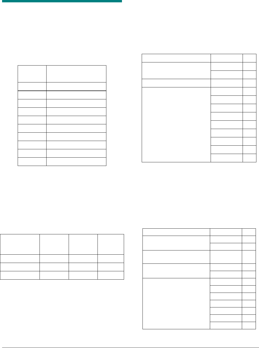
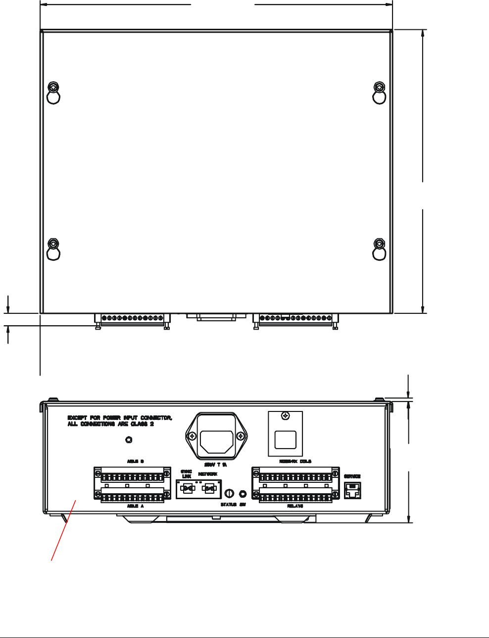
Specifications
For the electrical specifications, see Figure 15. For
the mechanical (i.e. size and weight) and
environmental specifications, see Figure 16.
DB25 male to DB9
male adapter
Null modem adapter
T adapte
r
Modem
RS232/RS485
converter
Preliminary
AMS-1070 CONTROLLER INSTALLATION GUIDE (8200-0127-06, REV. 0)
11 of 13
Figure 15. Electrical specifications
Input Powe
r
Voltage Range: 100-240Vac (50-60Hz)
Primary Power Fuse: 1A, 250V slo-blo
Input Power: < 30 W per controller (<15 W per aisle)
Current Draw: 0.75A peak
Transmitter/Receiver Ports
Ports: 2 (2 antennas per port)
Operating freq.: 58 kHz (+ 200 Hz)
Coil resistance: 13 Ohms (at 58 kHz)
Transmit current: 1 amp +/- 0.1 amps
Tx burst duration: 1.6ms
Burst rep rate: System Type 50Hz 60Hz
Two aisle 37.5 Hz 45 Hz
One aisle 75 Hz 90 Hz
Split receiver 37.5 Hz 45 Hz
Split receiver when 150 Hz 180 Hz
tag detected
Output Power: NEC Class 2
IEC950 Limited Power Source
Noise Coil Receive
r
Ports: 1 (2 antennas)
Center freq: 58 kHz
Preliminary
AMS-1070 CONTROLLER INSTALLATION GUIDE (8200-0127-06, REV. 0)
12 of 13
Figure 16. Mechanical and environmental specifications
26.15cm
(10 ¼ in)
21cm
8 ¼ in.
.94cm
(3/8 in)
2.5mm
(0.1 in)
89.7cm
(35 5/16 in)
Operating temperature: 0-40° C (32-104° F)
Non-operating temperature: -40 – 70° C (-40 - 158° F)
Relative humidity: 0-90% non-condensing
Weight (with power cord): 2.9kg (6.4 lbs.)

Preliminary
AMS-1070 CONTROLLER INSTALLATION GUIDE (8200-0127-06, REV. 0)
13 of 13
Declarations
Regulatory Compliance
Emissions .......................... 47 CFR, Part 15
EN 300 330
EN 301 489
Safety................................. UL 60950
CSA C22.2 No 60950
EN 60 950
FCC COMPLIANCE: This equipment complies with Part 15
of the FCC rules for intentional radiators and Class A digital
devices when installed and used in accordance with the
instruction manual. Following these rules provides reasonable
protection against harmful interference from equipment
operated in a commercial area. This equipment should not be
installed in a residential area as it can radiate radio frequency
energy that could interfere with radio communications, a
situation the user would have to fix at their own expense.
EQUIPMENT MODIFICATION CAUTION: Equipment
changes or modifications not expressly approved by
Sensormatic Electronics Corporation, the party responsible for
FCC compliance, could void the user's authority to operate the
equipment and could create a hazardous condition.
Other Declarations
WARRANTY DISCLAIMER: Sensormatic Electronics
Corporation makes no representation or warranty with respect
to the contents hereof and specifically disclaims any implied
warranties of merchantability or fitness for any particular
purpose. Further, Sensormatic Electronics Corporation
reserves the right to revise this publication and make changes
from time to time in the content hereof without obligation of
Sensormatic Electronics Corporation to notify any person of
such revision or changes.
LIMITED RIGHTS NOTICE: For units of the Department
of Defense, all documentation and manuals were developed at
private expense and no part of it was developed using
Government Funds. The restrictions governing the use and
disclosure of technical data marked with this legend are set
forth in the definition of “limited rights” in paragraph (a) (15)
of the clause of DFARS 252.227.7013. Unpublished - rights
reserved under the Copyright Laws of the United States.
TRADEMARK NOTICE: Sensormatic and the Sensormatic
logo are trademarks or registered trademarks of Sensormatic
Electronics Corporation Other product names mentioned
herein may be trademarks or registered trademarks of
Sensormatic or other companies.
No part of this guide may be reproduced in any form without
written permission from Sensormatic Electronics Corporation.
RWH -7/02
AMS-1070 EMI SHIELD INSTALLATION GUIDE (8200-0127-12, REV. A)
1 of 1
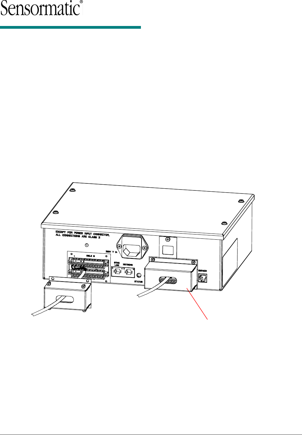
AMS-1070 Controller
EMI Shield
Installation Guide
Two EMI shields are required. To install each
shield:
1. Run the unterminated cable through the slot in
the shield from the direction shown, and then
connect the cable ends to the cable connector
according to wiring diagrams in AMS-1070
Controller Install Guide 8200-0127-06.
2. Attach the shield to the controller using the four
screws supplied.
© Sensormatic 2002
EMI Shield