Tyco Adc 660P Users Manual ADC660N_P Manual_Rev A_
ADC 660P to the manual 8b5f0c11-f9a9-4c35-ae32-7b74086c4342
2015-02-03
: Tyco Tyco-Adc-660P-Users-Manual-460815 tyco-adc-660p-users-manual-460815 tyco pdf
Open the PDF directly: View PDF ![]() .
.
Page Count: 19

Hi-Res. B/W camera
instruction manual
ADC 660N
ADC 660P
Version: Rev. A
Part Number 8200-0839-01
Notice
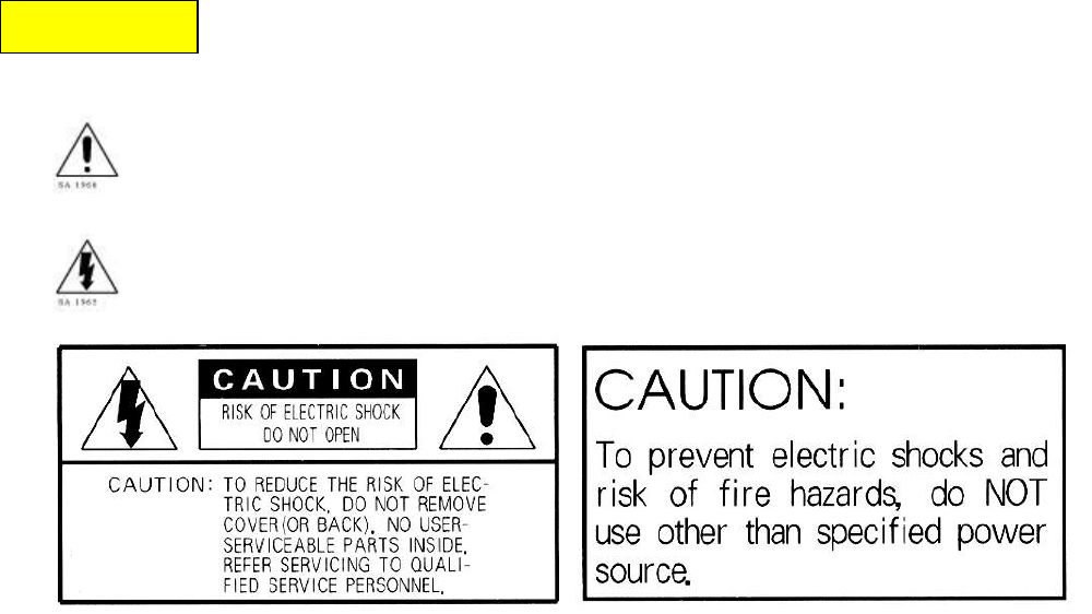
To prevent fire or shock hazard, do not expose the unit to rain or
moisture.
The symbol is intended to alert the user to the presence of important operating
and maintenance (servicing) instructions in the literature accompanying the unit.
The symbol is intended to alert the user to the presence of uninsulated
"dangerous voltage" within the product's enclosure that may be of
sufficient magnitude to constitute a risk of electric shock to persons.
Warning
This equipment has been tested and found to comply with the limits for a Class A digital
device, pursuant to part 15 of the FCC Rules. These limits are designed to provide
reasonable protection against harmful interference when the equipment is operated in a
commercial environment. This equipment generates, uses, and can radiate radio
frequency energy and, if not installed and used in accordance with the instruction manual,
may cause harmful interference to radio communications. Operation of this equipment in
a residential area is likely to cause harmful interference, in which case the user will be
required to correct the interference at his own expense.
Equipment Modification Caution
Equipment changes or modifications not expressly approved by Sensormatic Electronics
Corporation, the party responsible for FCC compliance, could void the user’s authority to
operate the equipment and could create a hazardous condition.
This class A digital apparatus complies with Canadian ICES-003.
Cet appareil numérique de la classe A est conforme à la norme NMB-003 du Canada.
WARNING

Caution
This installation should be made by a qualified service person and should conform to all
local and national electrical and mechanical codes.

PRECAUTIONS
1. Do not attempt to disassemble the camera.
In order to prevent electric shock, do not remove screws or cover. There are
no user-serviceable parts inside.
2. Do not expose the camera to rain or moisture, or try to operate it in wet
areas.
Take immediate action if the camera becomes wet. Turn the power off and refer
servicing to qualified service personnel. Moisture can damage the camera and
also create a danger of electric shock.
3. Do not use strong or abrasive detergents when cleaning the camera body.
Use a dry cloth to clean the camera when dirty. In a case where the dirt is
hard to remove, use a mild detergent and wipe gently.
4. Never point the camera toward the sun.
Whether the camera is used outdoors or not, never point it toward the sun.
Use caution when operating the camera in the vicinity of spot lights or other
bright lights and light reflecting objects.
5. Do not operate the camera beyond its temperature, humidity or power source
ratings.
Do not use the camera in an extreme environment where high temperature or
high humidity exists. Use the camera under conditions where temperatures are
between 14° F~122° F (-10° C~+50° C) and humidity is below 85%.
6. Use a 24V AC / 12V DC class 2 LPS supply only.

Hi-Res. B/W camera instruction manual
ADC 660N and ADC 660P
_________________________________
5
Copyright
©2007 Sensormatic Electronics Corporation.
Product specifications subject to change without notice. Certain product names
mentioned herein may be trade names and/or registered trademarks of other
companies.
Customer Service
Thank you for using American Dynamics products. We support our products through
an extensive worldwide network of dealers. The dealer through whom you originally
purchased this product is your point of contact if you need service or support. Our
dealers are empowered to provide the very best in customer service and support.
Dealers should contact American Dynamics at (800) 507-6268 or (561) 912-6259 or
on the Web at www.americandynamics.net.

Hi-Res. B/W camera instruction manual
ADC 660N and ADC 660P
_________________________________
6
I. CONNECTORS AND CONTROLS .................................................................................. 7
1. VIDEO OUTPUT CONNECTOR (BNC)................................................................................ 7
2. POWER INPUT CONNECTOR (SCREW TERMINAL) ............................................................... 7
3. AUTO IRIS LENS CONNECTOR FOR VIDEO DRIVE LENS .................................................... 8
4. AUTO IRIS LENS CONNECTOR FOR DC DRIVE LENS .......................................................... 8
5. BLC (BACKLIGHT COMPENSATION) ON/OFF SWITCH ...................................................... 9
6. ALC/ELC SELECT SWITCH (EE/ELC IS ON; ALC/AI IS OFF) ....................................... 10
7. AGC ON/OFF SWITCH ............................................................................................... 11
8. INT/LL SWITCH (LL IS ON; INT IS OFF) ...................................................................... 11
9. FL ON SWITCH (FLICKERLESS ON/OFF)...................................................................... 11
10. V-PHASE ADJUSTMENT POTENTIOMETER....................................................................... 11
11. ALC LEVEL ADJUSTMENT POTENTIOMETER FOR DC DRIVE LENS.................................... 13
12. POWER INDICATOR LED ............................................................................................... 14
13. BACKFOCUS ADJUSTMENT SCREW ................................................................................ 14
14. C MOUNT ADAPTOR RING ............................................................................................ 16
15. CCD DUST PROTECTIVE CAP ....................................................................................... 16
16. CAMERA MOUNT HOLE ................................................................................................. 16
17. CAMERA MOUNT BASE ................................................................................................. 16
II. EXAMPLES OF CONNECTIONS .................................................................................. 17
1. SIMPLEST: ONE MONITOR SYSTEM WITH ONE CAMERA ..................................................... 17
2. ONE MONITOR SYSTEM WITH TWO OR MORE CAMERAS..................................................... 17
III. DIMENSIONS................................................................................................................. 18
IV. SPECIFICATIONS ......................................................................................................... 19
Hi-Res. B/W camera instruction manual
ADC 660N and ADC 660P
_________________________________
7
I. CONNECTORS AND CONTROLS
1. Video Output Connector (BNC)
1.0V p-p/75Ω composite video signal is provided at this connector.
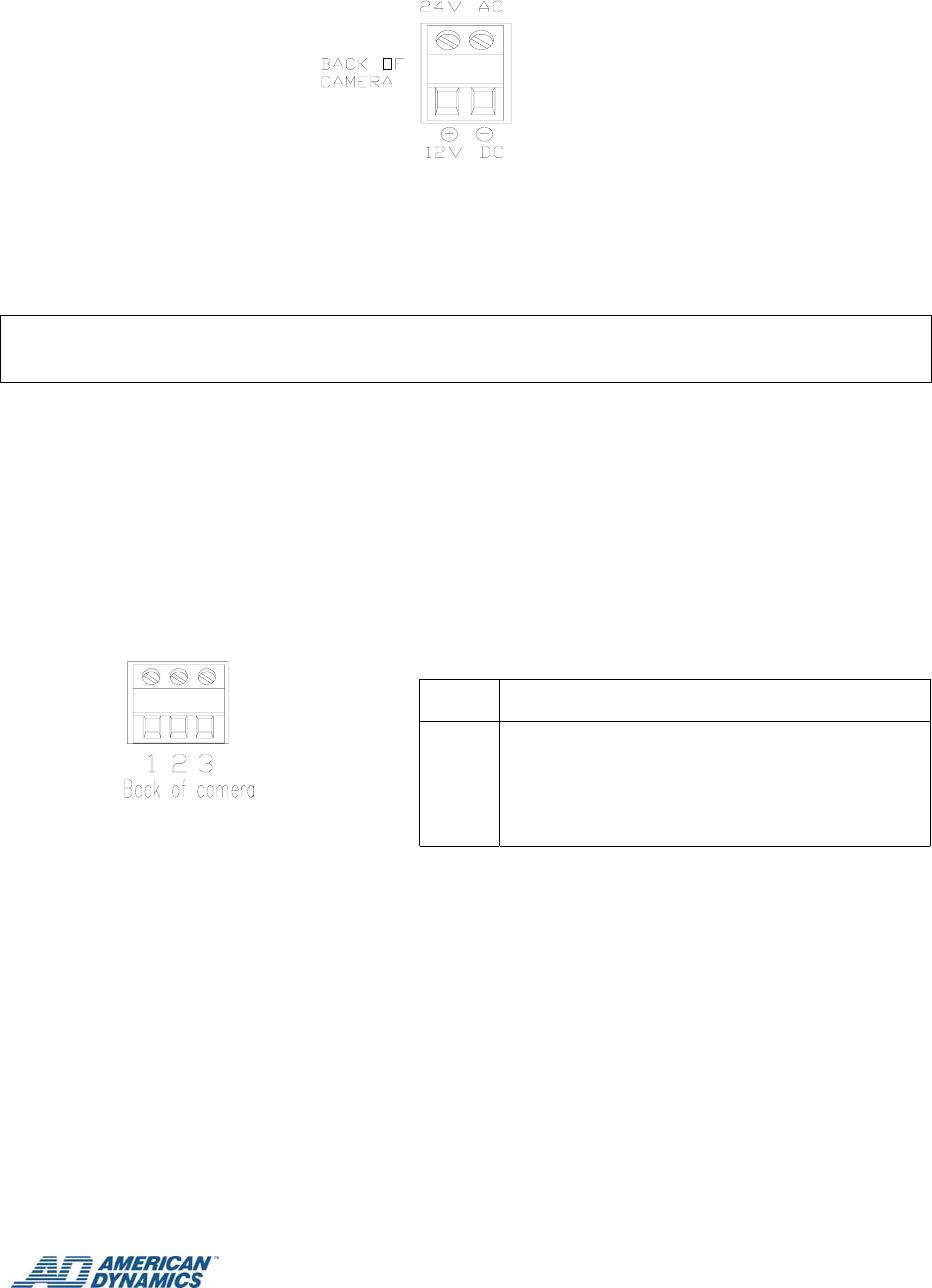
2. Power Input Connector (screw terminal)
Hi-Res. B/W camera instruction manual
ADC 660N and ADC 660P
_________________________________
8
This terminal accepts 12 VDC or 24 VAC.
Power Requirement: Maximum 200 mA (12 VDC), Maximum 100 mA (24 VAC).
Recommended Power Supply: Minimum 500 mA (12 VDC); Minimum 300 mA (24 VAC).
Caution:
Use a 24V AC / 12V DC class 2 LPS supply only.
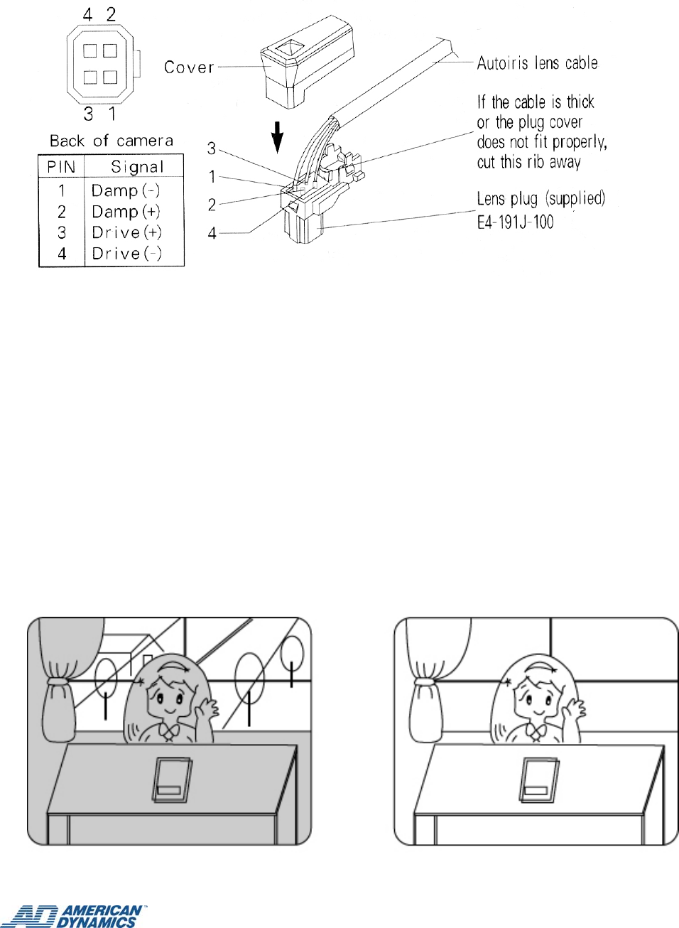
3. Auto Iris Lens Connector for VIDEO Drive Lens
This connector supplies 9 VDC power and video signal, without sync, for video-drive
type Auto Iris lens.
When using a VIDEO drive lens, the ALC/ELC DIP #1 must be set to the ALC (OFF)
position.
4. Auto Iris Lens Connector for DC Drive Lens
This connector supplies the control signals to the DC drive Auto Iris lens.
PIN Signal
1
2
3
GROUND
POWER SUPPLY (9 VDC, 40mA)
VIDEO OUTPUT (0.7Vp-p without sync)
Hi-Res. B/W camera instruction manual
ADC 660N and ADC 660P
_________________________________
9
When using a DC drive lens, the ALC/ELC DIP #1 must be set to the ALC (OFF)
position.
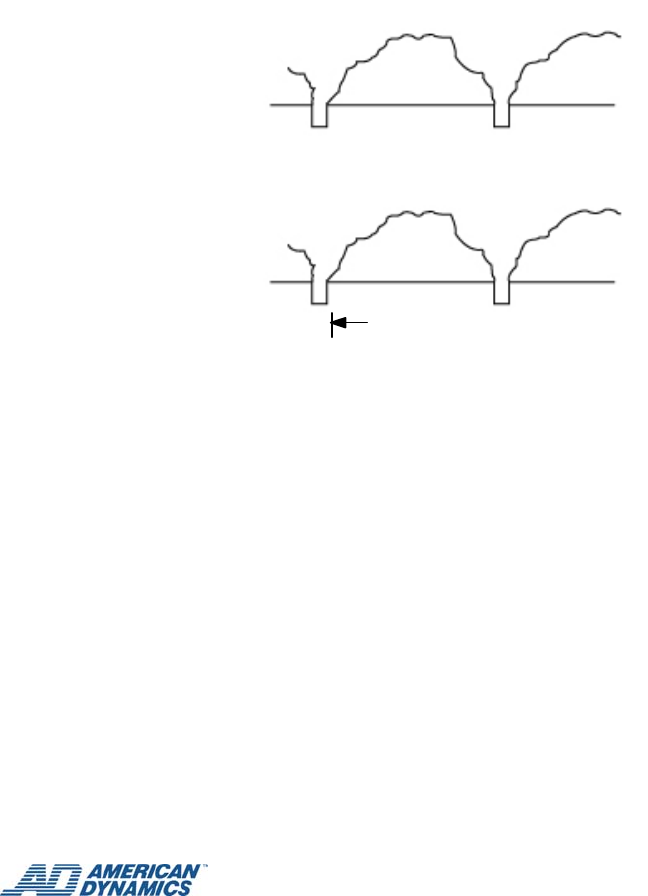
5. BLC (Backlight Compensation) ON/OFF Switch
If the subject you wish to view is too dim because of a bright background, set the
BLC DIP switch #2 to ON to compensate for the bright background.
With BLC on, the background brightness may saturate in some cases. This
function may not operate properly if the object is too small compared to the area
of the background. This function can be used with either the linear shutter (EE or
ELC mode) or an Auto Iris lens (AI lens or ALC mode).
WITH BLC OFF WITH BLC ON

Hi-Res. B/W camera instruction manual
ADC 660N and ADC 660P
_________________________________
10
6. ALC/ELC Select Switch (EE/ELC is ON; ALC/AI is OFF)
This switch is used to select EE (electronic exposure)/ELC (electronic light control)
mode or AI (Auto Iris lens)/ALC (automatic light control) mode. DIP switch 1 is set
to ON for EE/ELC and OFF for AI/ALC.
In the EE/ELC mode, a continuously variable electronic shutter is employed to
automatically control the exposure time of the CCD image sensor according to the
incoming light level. With this mode selected, a fixed or manual iris lens can be
used instead of an Auto Iris lens. In the AI/ALC mode, the CCD shutter speed is
fixed to 1/60 (1/50) sec, and the incoming light level is controlled by the Auto Iris
lens. To use a video-drive type or the DC-drive type of Auto Iris lens, set this
switch to the ALC position.
Cautions
Under bright lighting conditions such as outdoors, use an Auto Iris lens
because the EE/ELC control range is not wide enough under these
conditions.
Under certain unique lighting conditions, the following phenomena may
appear:
Strong smear and/or blooming on highlighted objects such as spotlights
or windows.
Noticeable flicker in the picture and/or color rendition variations. To
avoid this, use an Auto Iris lens.
When operating in EE/ELC mode with manual iris lens, the depth of field of
the image may be less than that obtained by using an AI/ALC lens. Depth
of field varies inversely with the iris opening. Thus, using this camera in
EE/ELC mode with the manual iris lens fully opened may result in less depth
of field and the distant objects in a picture may be seen out of focus.
Fixed iris or manual iris lenses may be used with the linear shutter (EE/ELC
mode) where the scene brightness varies over a limited range.
Do not use the EE/ELC mode when an Auto Iris lens is installed.

Hi-Res. B/W camera instruction manual
ADC 660N and ADC 660P
_________________________________
11
7. AGC ON/OFF Switch
This switch is provided for the AGC circuit. The AGC circuit incorporated into the
camera boosts the sensitivity automatically when the scene illumination is
insufficient.
8. INT/LL Switch (LL is ON; INT is OFF)
This camera can operate independently, using its internal crystal-controlled sync
generator, or it may be synchronized using line-locking.
To select one or the other of these sync modes, set the DIP switch on the rear
panel to either INT or LL. Switch 4 is set to ON for LL and OFF for INT.
If line-lock is selected, all the cameras in the system must be adjusted to begin the
video field scan at the same time. This is described in procedure ⑩.
9. FL ON Switch (Flickerless ON/OFF)
This function is only used in JAPAN. In order to use FL mode, set EE/AI
switch to AI first and then FL ON/OFF switch to ON.
When the DIP switch on the rear panel is set to ON, the shutter speed is
fixed at a rate of 1/100(120)(sec).
10. V-Phase Adjustment Potentiometer
This potentiometer is set full counter clockwise at the factory. If two or
more cameras are connected to a switcher and the picture on the monitor rolls
while switching from camera A to B, adjusting the vertical phase (V-phase) of
the cameras will probably eliminate the rolling. If this adjustment is
necessary, it should only be performed by a qualified technician. Before
making any adjustment, confirm that cameras A and B are connected to the
power supply with the same polarity.
To make an adjustment, follow the steps below.
Hi-Res. B/W camera instruction manual
ADC 660N and ADC 660P
_________________________________
12
1. While observing the video output signals from both cameras on an
oscilloscope, turn camera A's V-phase control (on back of camera)
until vertical sync from both cameras is in phase.
2. If camera A's adjustment range is insufficient, adjust camera B's V-
phase control in the opposite direction to camera A until they are in
phase.
3. If these adjustments do not bring vertical sync from both cameras in
phase, recheck the polarity of the power supply connections.
Camera A's VIDEO OUT
Camera B's VIDEO OUT
Should be in phase
If an oscilloscope is not available, a less accurate adjustment can be made by
observing the monitor and adjusting the V-phase control potentiometer until no
roll occurs on the monitor when switching back and forth between cameras A and B.
Hi-Res. B/W camera instruction manual
ADC 660N and ADC 660P
_________________________________
13
11. ALC Level Adjustment Potentiometer for DC Drive Lens
This potentiometer is used only if the camera is fitted with a DC drive Auto Iris lens.
It is used to control the amount of light striking the CCD image sensor.
Turn off AGC. With a brightly lit scene adjust LENS-IRIS control for a clean 1 VPP
video level with no blooming. Turn AGC back on after adjustment is complete.
LEVEL
LENS-IRIS level control
LH

Hi-Res. B/W camera instruction manual
ADC 660N and ADC 660P
_________________________________
14
Monitor Screen LEVEL Control Direction
To increase the brightness Clockwise
To decrease the brightness Counterclockwise
12. Power Indicator LED
This LED turns ON only when power is supplied properly and the DC-DC converter
(or the regulator) inside the camera works properly.
13. Backfocus Adjustment Screw
This screw is used to position the CCD image sensor at the precise point of focus of the
lens.
Backfocusing Fixed-Focal or Vari-Focal Length Lenses
Install a lens and connect the camera to a monitor and power supply as
described in this manual.
Open the iris completely or just before there is blooming in the picture. If an
Auto Iris lens is used, reduce the room lighting to use a neutral density filter to
allow the lens to open completely. This gives the most accurate results.
Adjust the screw slowly until the sharpest picture is obtained. This completes the
adjustment. The back-focus adjustment screw is held in place by friction, so
there is no locking screw to tighten.
Backfocusing Zoom Lenses
Install a lens and connect the camera to a monitor and power supply.
Position the camera 10~30 feet (3~9 meters) from a flat vertical surface
suitable for focusing. A newspaper works well as a focusing target.
Open the iris completely or just before there is blooming in the picture. If an
Auto Iris lens is used, reduce the room lighting or use a neutral density filter to
allow the lens to open completely. This gives the most accurate results.
1. Zoom the lens in to the maximum telephoto setting. Adjust the optical
focus of the lens for the sharpest picture.
2. Zoom out to the maximum wide angle setting. If the picture is no longer in
focus, readjust the back-focus screw to obtain the best focus possible.
3. Repeat steps 1 and 2 until the image remains sharp through the entire
zoom range without having to make any focus adjustments.
This completes the adjustment. The back-focus adjustment screw is held in
place by friction, so there is no locking screw.

Hi-Res. B/W camera instruction manual
ADC 660N and ADC 660P
_________________________________
15

Hi-Res. B/W camera instruction manual
ADC 660N and ADC 660P
_________________________________
16
14. C Mount Adaptor Ring
The C-mount adaptor ring is used only if a C-mount lens is used on the camera. If a CS-
mount lens is used, the adaptor is not necessary. To install the adaptor, first screw it
into the lens mount opening on the camera. Then screw the C-mount lens into the
adaptor.
15. CCD Dust Protective Cap
Remove this cap before installing the lens.
Do not handle or leave the camera with cap open.
16. Camera Mount Hole
17. Camera Mount Base
Hi-Res. B/W camera instruction manual
ADC 660N and ADC 660P
_________________________________
17
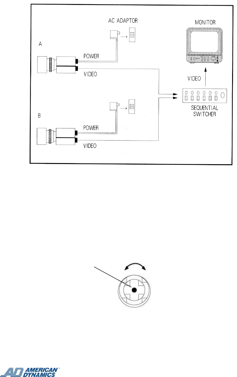
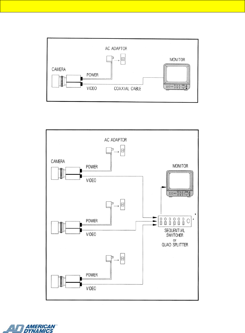
II. EXAMPLES OF CONNECTIONS
1. Simplest: One monitor system with one camera
2. One monitor system with two or more cameras
Hi-Res. B/W camera instruction manual
ADC 660N and ADC 660P
_________________________________
18
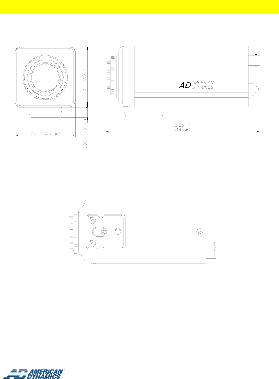
III. DIMENSIONS

Hi-Res. B/W camera instruction manual
ADC 660N and ADC 660P
_________________________________
19
IV. SPECIFICATIONS
MODEL ADC660N ADC660P
TV SYSTEM EIA CCIR
EFFECTIVE PIXELS 768(H) X 494(V) 752(H) X 582(V)
IMAGE DEVICE 1/3” INTERLINE TRANSFER CCD
SCANNING SYSTEM 2:1 INTERLACE
SYNCHRONIZING SYSTEM INTERNAL/LINE LOCK SELECTABLE
HORIZONTAL RESOLUTION 580 TV LINE
VIDEO OUTPUT LEVEL 1 V pp/75 ohm
S/N RATIO MORE THAN 50 dB (AGC OFF)
MIN.ILLUMINATION (F1.2) 0.03 lux
ELECTRONIC IRIS 1/60 ~ 1/100,000 SEC 1/50 ~ 1/100,000 SEC
LINE LOCK RANGE 60 Hz ± 1 Hz 50 Hz ± 1 Hz
BACKLIGHT COMPENSATION ON/OFF SELECTABLE (CENTER ZONE WEIGHTED)
BACKFOCUS ADJUSTMENT FINE ADJUSTMENT WITH SELF LOCKING SYSTEM
CAMERA MOUNT 1/4-20 UNC (TOP or BOTTOM SELECTABLE)
LENS MOUNT C- or CS-MOUNT (C-MOUNT ADAPTOR RING INCLUDED)
AUTO IRIS SUPPORT VIDEO-DRIVE TYPE WITH 3P TERMINAL
DC-DRIVE TYPE WITH 4P SQUARE CONNECTOR
POWER REQUIREMENT 12V DC ± 20% 200mA MAX/24V AC ± 20% 100mA MAX
OPERATION CONDITION 14° F TO 122° F (-10℃~50℃) WITHIN 85% RELATIVE HUMIDITY
NET WEIGHT
(WITHOUT LENS) APPROX. 0.9 lb (400 g)
DIMENSIONS (W x H x L) 2.2 in. x 2.2 in. x 5.55 in. (55 x 55 x 141 mm)
