U IT CCR-900 900 MHz RF Reader User Manual CCR 900 user s manual
U-IT CO., LTD. 900 MHz RF Reader CCR 900 user s manual
U IT >
Users Manual
User’s Manual
CCR-900
U-IT Co., Ltd.
TABLE OF CONTENTS
1. GENERAL.....................................................................................................................................................1
2. PRODUCT SPECIFICATION.....................................................................................................................2
2.1. RF READER SPECIFICATION ...............................................................................................................................2
2.2. RF TAG SPECIFICATION ......................................................................................................................................2
2.3. COMMUNICATION SPECIFICATION ......................................................................................................................3
3. FEATURES ...................................................................................................................................................4
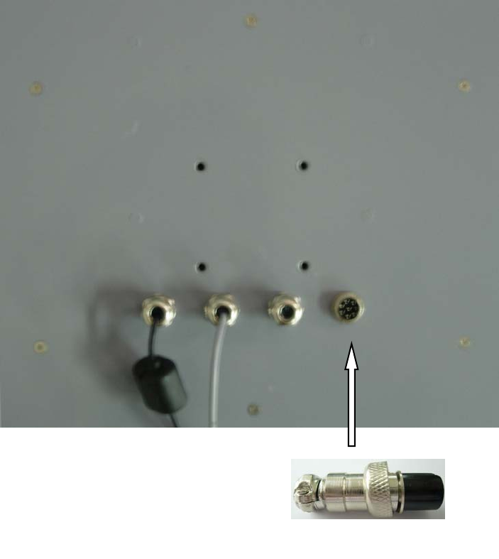
4. INTERFACE AND CONNECTION ...........................................................................................................5
4.1. TB201(DC POWER CABLE) ...............................................................................................................................6
4.2. TB202(HOST MODE, IN/OUT CABLE) .............................................................................................................. 6
4.3. CN103(TAG REGISTER / PROGRAM UPGRADE))................................................................................................6
4.4. INPUT PORT........................................................................................................................................................6
4.5. OUTPUT(A POINT OF CONTACT RELAY) PORT:....................................................................................................6
5. DIP SWITCH SETUP...................................................................................................................................7
5.1. COMMUNICATION SETUP DIP SWITCH(SW101).................................................................................................8
5.2. COMMUNICATION LINE SETUP DIP SWITCH(SW103) .........................................................................................8
5.3. OPERATION SETUP DIP SWITCH(SW102)........................................................................................................... 9
5.4. RELAY SETUP DIP SWITCH(SW201).................................................................................................................. 9
6. COMMUNICATION CONNECTION METHOD...................................................................................10
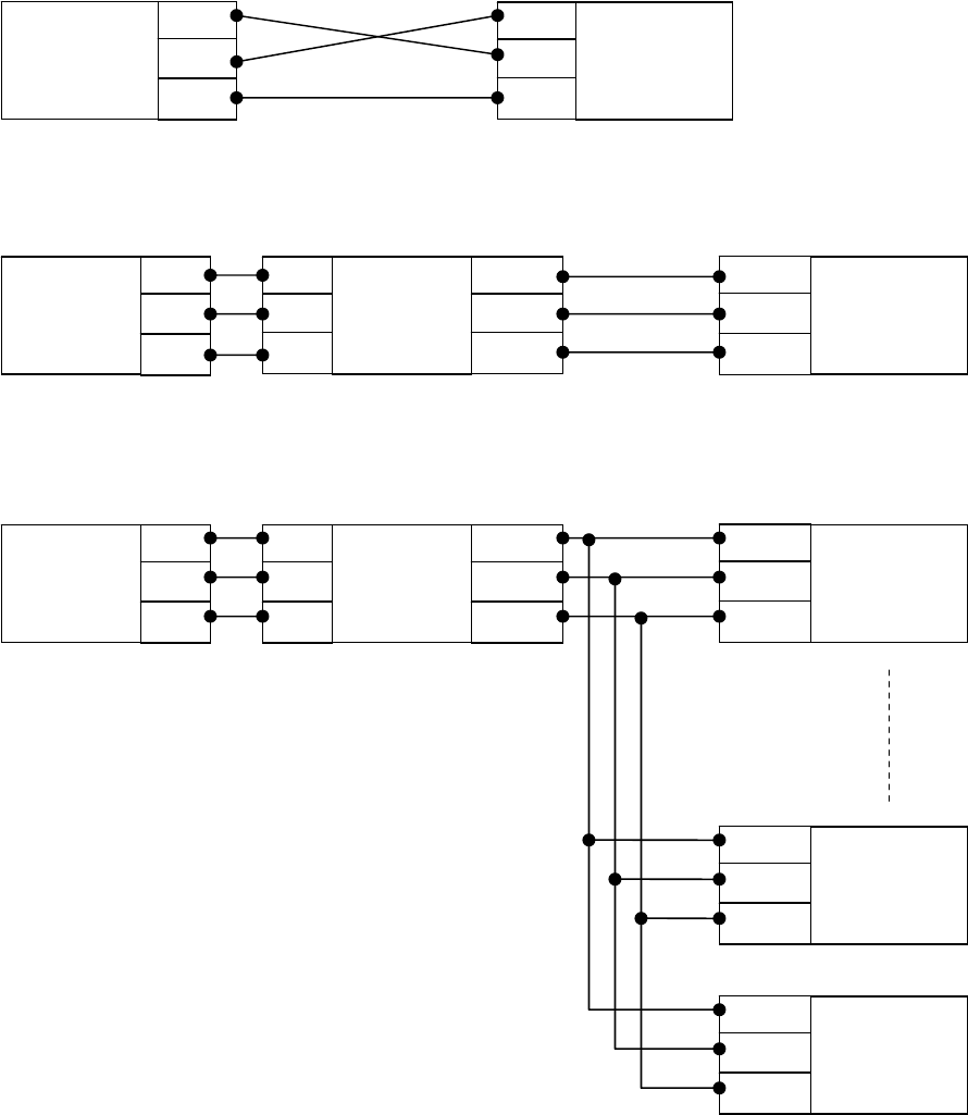
6.1. HOST COMPUTER OR TF-3700C CONTROLLER AND RS-232C CONNECTION....................................................10
6.2. HOST COMPUTER OR TF-3700C CONTROLLER AND RS-485 CONNECTION (1:1)..............................................10
6.3. HOST COMPUTER OR RS-485 CONNECTION (1:N)............................................................................................10
7. PRODUCT APPLICATION ......................................................................................................................11
7.1. STAND ALONE MODE ....................................................................................................................................... 11
7.1.1. RFID TAG Registration...............................................................................................................11
7.1.2. Communication Setup DIP Switch (SW101) Setup ....................................................................11
7.1.3. Operation Setup DIP Switch (SW102) Setup..............................................................................12
7.1.4. Relay Setup DIP Switch (SW201) Setup.....................................................................................12
7.2. COUPLED MODE...............................................................................................................................................12
7.2.1. Communication Setup DIP Switch (SW101) Setup ....................................................................12
7.2.2. Operation Setup DIP Switch (SW102) Setup..............................................................................12
7.2.3. Communication Line Setup DIP Switch (SW103) Setup............................................................12
7.2.4. Relay Setup DIP Switch (SW201) Setup.....................................................................................12
7.3. TEST MODE......................................................................................................................................................12
7.3.1. Communication Setup DIP Switch (SW101) Setup ....................................................................12
7.3.2. Operation Setup DIP Switch (SW102) Setup..............................................................................13
7.3.3. Communication Line DIP Switch (SW103) Setup......................................................................13
7.3.4. Relay Setup DIP Switch (SW201) Setup.....................................................................................13
7.3.5. Test List .......................................................................................................................................13
8. COMMUNICATION PROTOCOL ..........................................................................................................14
8.1. TRANSMISSION CONTROL CODE ......................................................................................................................14
8.2. RFID TAG READING TRANSMISSION FRAME ..................................................................................................14
8.3. COMMAND REQUEST FRAME (HOST ÆREADER) .............................................................................................15
8.4. RESPONSE FRAME (READER Æ HOST)............................................................................................................. 16
8.5. TRANSMISSION ORDER ....................................................................................................................................16
8.5.1. Normal Operation: TAG is read during the TAG Reading Standby Mode, Transmitted Valid TAG ID to
the HOST .....................................................................................................................................................16
8.5.2. Normal Operation: TAG is read during the TAG Reading Standby Mode, Transmitted Invalid TAG ID
to the HOST..................................................................................................................................................17
8.5.3. Positive Response after one Command Request Frame has been transmitted.............................17
8.5.4. Negative Response after one Command Request Frame has been transmitted ...........................18
8.5.5. When many numbers of Command Request Frame have been transmitted ................................19
8.6. PRODUCT IMAGE..............................................................................................................................................20

8.6.1. MAIN PCB..................................................................................................................................20
8.6.2. Frontal View................................................................................................................................21
8.6.3. Rear View....................................................................................................................................22
9. PRODUCT INSTALLATION....................................................................................................................23
9.1. RFID TAG POSITIONING AREA FOR THE VEHICLE ...........................................................................................23
9.2. PRODUCT INSTALLATION LOCATION.................................................................................................................24
9.2.1. Installation location at the two lanes road with a center divider being present ...........................24
9.2.2. Installation location at the two lanes road without a center divider being present ......................25
9.2.3. Installation location at the T type intersection where a center divier is located at the entrance ..26
9.2.4. Installation location at the T type intersection without a center diviers being present ................27
9.2.5. General Installation tip for all the other cases .............................................................................28
1. General
This RF Reader uses 900MHz range of radio frequency to read the RFID TAG attached to the car. TAG’s ID data is
then transmitted to the Host Computer or Access controller through this RFID reader in Real time to allow the control
over the regularly parking authorized cars.
The reader is capable of reading the passive type of RFID TAG from 0.2m to 6m if RFID TAG is positioned
directly at the front of it. However, it does not read or detect the RFID TAG that is position behind it.
Also, RF Reader provides a relay output that can be connected to the bar gate control open the bar gate.
In order to operate as Standalone device, the reader also contains memory buffer which can store valid ID.
Registration of Valid ID can be handled directly from the reader.
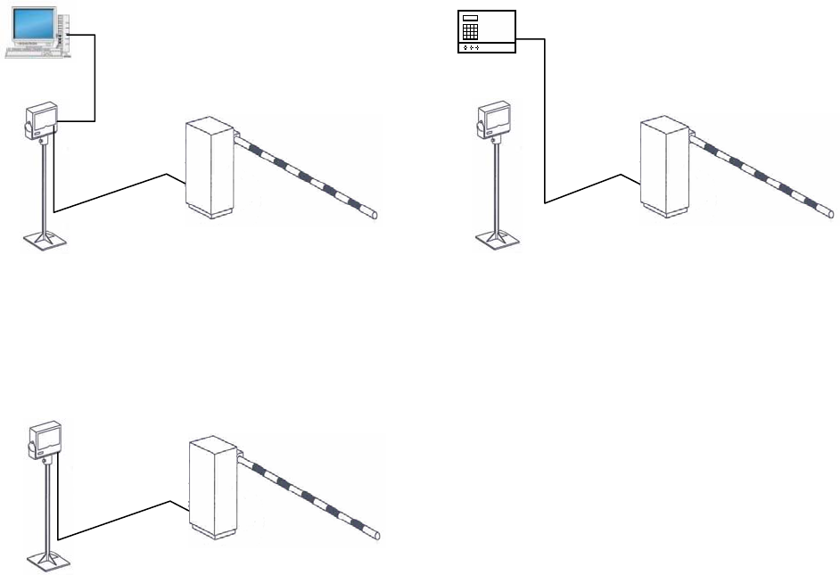
<Picture 1-1.Host Computer linked Operation> <Picture 1-2. Controller linked Operation>
<Picture 1-3. Stand alone operation>
RF Reader
BAR GATE
RS-232C or RS485
RF Reader
BAR GATE
RS-232C or RS485
Open Signal
RF Reader
BAR GATE
Open Signal
2. Product Specification
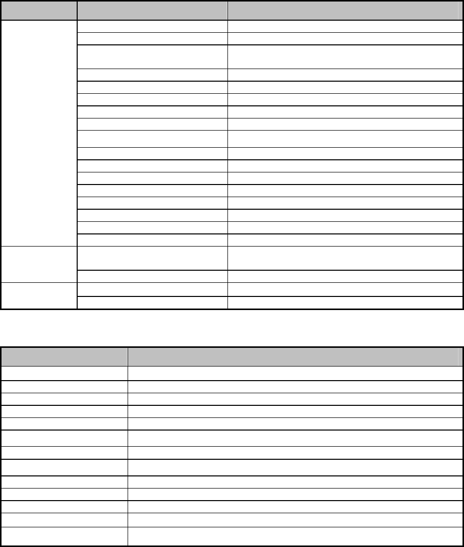
2.1. RF Reader Specification
Section Case Detail
Power / Current DC 12V / 3.5A
Current Drain 800mA, MAX 1.5A
Frequency 903.6 ~ 913.4Mhz Frequency Hopping Spread
Spectrum (FHSS)
Transmission Output 1 Watt (+30dBm) / based on antenna input point
Channel intervals 200KHz
Channel Bandwidth 200KHz
Communication Speed 40Kbps
Modulation DSB-ASK
Transmission Spectrum Mask ISO-18000-6 compliance
Spurious Transmission RFID Technology Standards compliance
Receive Gain -25dBm ~ -70dBm
Accuracy of frequency 10ppm
Reading Distance 0.5m ~ 6m
Protocol ISO18000-6B, ISO18000-6C
Multi-tag Read 5 Tags per Second (Protocol dependent)
Polarization Circular Polarization, Optional-Vertical or Horizontal
Reader
Host Communication RS-232C, RS-485
Input 1 loop line input Port, Bar Gate S/W Input, Firmware
upgrade Pin
Interface
Output(Dry contact Relay) 2 Bargate open output
Operating Temperature -30 ~ +85 ℃
Environmental
Condition Operating Humidity 0-95%, Non-Condensing
2.2. RF Tag Specification
Section Detail
Standard Application ISO 18000-6B
Operating Frequency 860~960MHz
Reading Distance 0.2m ~ 6 m
Data 64bit Unique ID
Programmable data 8192 bit
Bit rate 40kbps
Anti-collision Random number delay
Power Source Beam Powered
Error Detection Preamble & 16bit CRC
Modulation Type Load Modulation
Material ABS
Operating Temperature -40℃ ~ +75℃
Size 85.60 x 53.98 x 3.00±0.08mm
2.3. Communication Specification
Type Detail
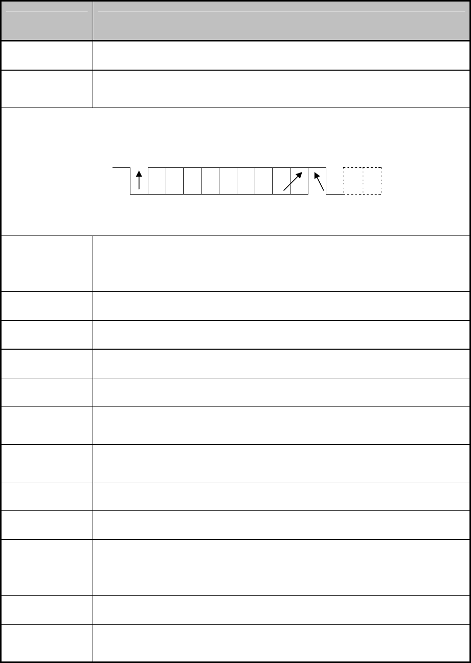
Interface RS-232C or RS-485 (refer to DIP switch setting)
Communication
Method Half – Duplex communication method
Asynchronous communication method /Transmission bit order
L:LSB (Least Significant bit ) M:MSB(Most Significant bit )
MARK(1)
L M
SPACE(0) Start bit Parity bit Stop bit
Protocol
ID Transmission immediately after decoding the Tag data (Check Circuit condition
before RS485 setting)
Request / Response format
Bits per Second 9600 bps (Fixed)
Data Bit 8 Bit (Fixed)
Parity Bit None (Fixed)
Stop Bit 1 Bit (Fixed)
Error Detection
Method Longitudinal Redundancy Check (LRC)
Transmission
CODE ASCII CODE (Standards)
Circuit Control Standard DATA transmission based upon order of the event transaction
RS control ON only at the transmission
Circuit
Communication
Status Display
Mark
Address Address 1 ~ 31can be setup using DIP Switch (Refer to DIP Switch Setup)
Terminal
Resistance
Terminal Resistance can be applied or removed if RS-485 is used. (using Jumper Switch
or Switch)

3. Features
Section Detail
Operation Mode
1).Stand Alone Mode: Contains memory space (Independent database) to register Tag ID. When
registered Tag ID is scanned, Relay is triggered.
2).Coupled Mode: When RF ID Tag has been read, Tag ID is transmitted to the host and the
reader receives and processes the command which has been sent by the host. (Reader’s Database
is not used)
3).Test Mode: It runs series of tests on reader’s ability including the decoding read range. Relay
output points and other things. ( When RF ID Tag is decoded, a relay output is triggered and the
data is sent in as standalone mode)
Buzzer
Sound can be disabled to prevent loud noise caused by buzzer occurring in the middle of the
night.(Buzzer is disabled)
1). When RFID Tag’s decoding mode or management mode has been changed, the reader will
makes a short beep.
2). During the test mode, if RFID Tag is present within the read range, the reader will
continuously beep.
LED(2 Colors)
Normal mode LED which is red continuously flickers in 1 second interval during the transaction
to show that the reader is in operation.
1). Green LED light flickers when RFID Tag is read.
2). Green LED light flickers when command is transmitted.
3). Green LED light continuously flickers in 1 second interval while executing the test mode.
Reading Method 1). normal reading mode
2). Vehicle Detection hold input reading mode
Reading mode
1). Same RFID Tag is continuously verified
For the same RFID Tag that exists within the decoding read range, Tag ID is verified within
the predefined time frame and then transmitted to the Host.
2). Same RFID Tag is scanned only once.
For the Same RFID Tag that exists within the decoding read range, Tag ID is read only once
and then it is sent to the host..
(Therefore, If same RFID Tag is to be read and verified, RFID Tag needs to go outside the
decoding read range then enter back into the decoding read range.)
Reading Time
Interval
Decoding time interval is only valid when reading mode is configured as continuous reading
mode and decoding time interval for the same ID Tag scanned at the reader is set for 5 seconds
fixed.
Reading Distance
Setup Capable maximum read range is always set on maximum range.
Relay output
configuration
1). Relay is triggered by the command sent by the host(Command) or relay is triggered by
decision made by reader’s own Database.
2).Relay is always triggered whenever RFID Tag is read.
4. Interface and Connection
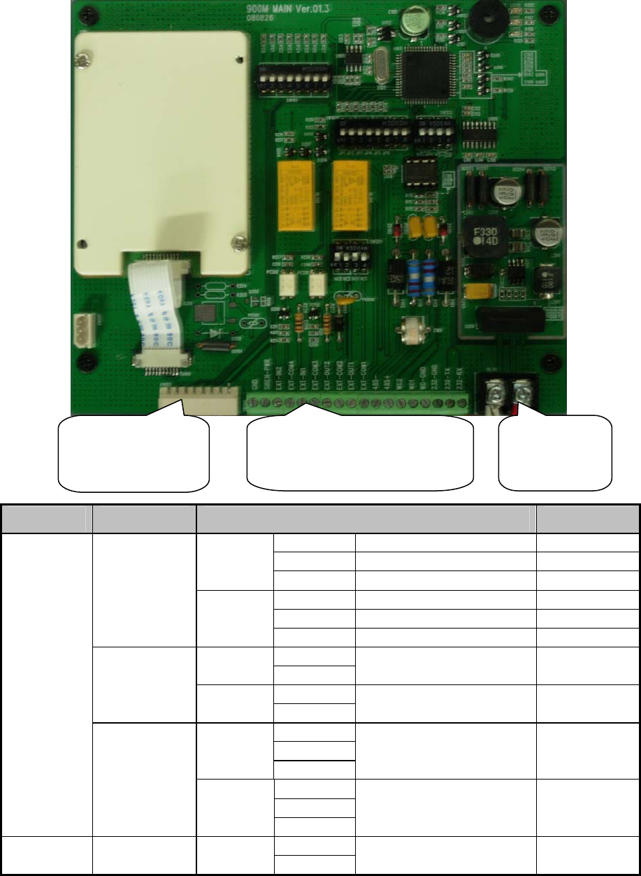
Section Type Detail Remark
TX
RX
RS-232C
GND
TRX+
TRX-
Host
Communication
RS-485
GND
Terminal 1
Input1 Terminal 2
Bargate Loop detection wire
Input(A Point of contact)
Terminal 1
Input
Input2 Terminal 2
Tag ID Registration input
Button Switch Input
NO
NC
Relay 1
COM
Bargate Output for opening
NO
NC
Interface
Output
(Relay
connection
point) Relay 2
COM
Bargate Output for closing or
others
DC+
Etc… DC Power DC Power GND DC power line 12V 5A
TB101
Power Connector
CN103
TAG Registration port
TB202
communication,IN/OUT cable connector
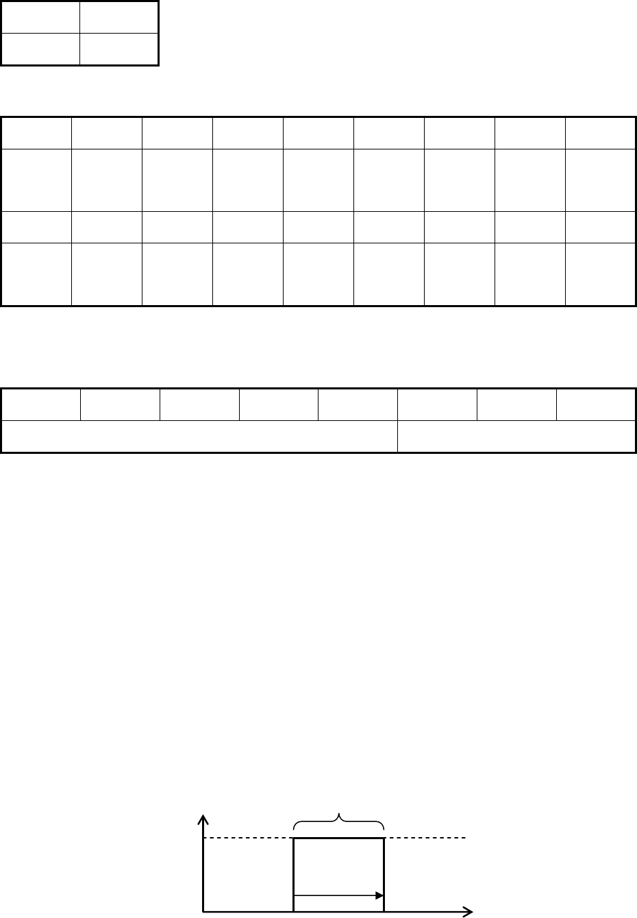
4.1. TB201(DC Power Cable)
1 2
+12V GND
4.2. TB202(Host Mode, IN/OUT Cable)
1 2 3 4 5 6 7 8 9
GND SIREN
PWR
EXT
IN2
EXT
COM4
EXT
IN1
EXT
COM3
EXT
OUT2
EXT
COM2
EXT
OUT1
10 11 12 13 14 15 16 17 18
EXT
COM1
485(-) 485(+) WD2 WD1 WD
GND
232
GND
232
TX
232
RX
4.3. CN103(TAG Register / Program Upgrade))
1 2 3 4 5 6 7 8
Program Upgrade TAG ID Register
4.4. Input Port
Input1: Dry Contact Input is received directly from the vehicle detection loop sensor. When the vehicle is detected,
dry contact input becomes ON mode from OFF mode.
Input2: When the operation mode is set in Stand alone mode, RF Reader’s Database is used to store the TAG ID
Number. TAG ID number can be stored by reading the TAG while the switch is pressed ON.
4.5. Output(A point of contact Relay) Port:
Relay output uses a point of contact trigger signal to open and close bargate..
Relay Trigger Signal:
On
Off T
(
msec
)
Rela
y
Tri
gg
er Si
g
nal
1000msec
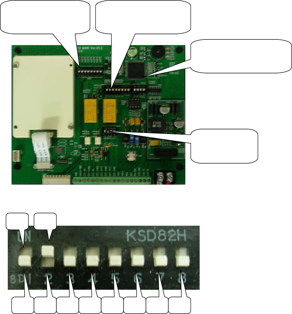
5. DIP Switch Setup
※Follow the above settings for Pin 8, Pin 4 of the DIP Switch.
OFF ON
SW1 SW2 SW3 SW4 SW5 SW6 SW7 SW8
SW101
Communication Setup DIP Switch
SW102
Operation Setup DIP Switch
SW201
Relay Setup DIP Switch
SW103
Communication Line Setup DIP Switch
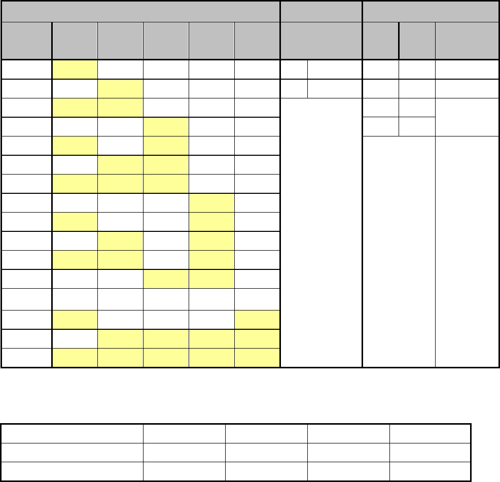
5.1. Communication Setup DIP Switch(SW101)
Address Setup( Default 1) TAG Type Setup Mode Setup
Address
(Value)
Sw 1
(1)
Sw 2
(2)
Sw 3
(4)
Sw 4
(8)
Sw 5
(16) Sw 6 Sw 7 Sw 8 Mode
1 On Off Off Off Off Off ISO 6B Off On Stand Alone
2 Off On Off Off Off On ISO 6C On Off Coupled
3 On On Off Off Off Off Off
4 Off Off On Off Off On On Test Mode
5 On Off On Off Off
6 Off On On Off Off
7 On On On Off Off
8 Off Off Off On Off
9 On Off Off On Off
10 Off On Off On Off
11 On On Off On Off
12 Off Off On On Off
: : : : : :
29 On Off Off Off On
30 Off On On On On
31 On On On On On
5.2. Communication line setup DIP Switch(SW103)
SW1 SW2 SW3 SW4
RS-232 communication OFF OFF ON ON
RS-485 communication ON ON OFF OFF
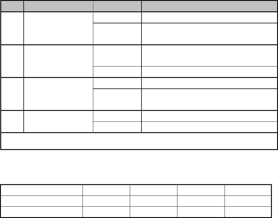
5.3. Operation Setup DIP Switch(SW102)
SW Setup Category Switch mode Setup Detail
Off RFID Tag reading at Normal mode
SW1 TAG recognition method On RFID Tag reading when vehicle present loop sensor input is
provided
Off One time reading mode (If Same RFID Tag is presented, it
will recognize it in every 5 seconds.)
SW2 Setup for the verification
On Continuous reading mode
Off Operation based on its own memory
SW3 Relay Setup On Relay operation based on the commands received by the host
unit.
Off RS-232
SW4 Communication Setup On RS-485
z In coupled mode, DATA is transmitted regardless of RFID Tag registration
5.4. Relay Setup DIP Switch(SW201)
NO1 NC1 NO2 NC2
NO TYPE ON OFF ON OFF
NC TYPE OFF ON OFF ON
6. Communication Connection Method
6.1. Host Computer or TF-3700C Controller and RS-232C connection
< Host Computer or TF-3700C > < RF READER >
6.2. Host Computer or TF-3700C Controller and RS-485 connection (1:1)
< Host Computer or TF-3700C > < RF READER >
6.3. Host Computer or RS-485 Connection (1:N)
RF READER
RS-232C
RX
TX
GND
HOST
RS-232C
RX
TX
GND
485
Converter
RX
TX
GND
HOST
RS-232C
RX
TX
GND
RF READER
RS-485
TRX +
TRX -
GND
TRX +
TRX -
GND
RF READER
RS-485
TRX +
TRX -
GND
RF READER
RS-485
TRX +
TRX -
GND
485
Converter
RX
TX
GND
HOST
RS-232C
RX
TX
GND
RF READER
RS-485
TRX +
TRX -
GND
TRX +
TRX -
GND
7. Product Application
7.1. Stand Alone Mode
Contains memory space (Independent database) to register Tag ID. When registered Tag ID is scanned, Relay is
triggered.
7.1.1. RFID TAG Registration
When TAG Registration CAP is connected at CON4 located at the back of the reader, RFID TAG scanned at the
reader is being registered.
7.1.2. Communication Setup DIP Switch (SW101) Setup
SW1~SW5 is set as OFF (Default)
SW6 is set as OFF when ISO 6B Tag is being used, ON when ISO 6C Tag is being used.
SW7 is set as OFF, SW8 is set as ON
CON4
CON3CON2CON1
TAG Registration CAP
7.1.3. Operation Setup DIP Switch (SW102) Setup
SW1 is set as ON when Vehicle Detection Loop signal is present. Otherwise, Set as OFF
SW2 is set as ON when verified every 5 seconds. Set as OFF is verified continuously.
SW3 is set as OFF (Independent Database)
SW4 is set as OFF (Default)
7.1.4. Relay Setup DIP Switch (SW201) Setup
Setup which falls under a given condition (refer to section 5.4 on page 8)
7.2. Coupled Mode
Tag ID is sent to the superior position (Host) when RFID Tag is read and Command received from the Host is then
executed. (Reader’s own Datable is not used)
Compatible communication method is selected for the communication between the reader and the host.
7.2.1. Communication Setup DIP Switch (SW101) Setup
Set SW1~SW5 compatible for specified ID
SW6 is set as OFF when ISO 6B Tag is being used, ON when ISO 6C Tag is being used.
SW7 is set as ON, SW8 is set as OFF
7.2.2. Operation Setup DIP Switch (SW102) Setup
SW1 is set as ON when Vehicle Detection Loop signal is present. Otherwise, Set as OFF
SW2 is set as ON when verified every 5 seconds. Set as OFF is verified continuously.
SW3 is set as ON (Independent Database not used)
SW4 is set as OFF when RS-232 communication method is being used, OFF when RS-485 communication method
is being used.
7.2.3. Communication Line Setup DIP Switch (SW103) Setup
Communication Setup which falls under a given condition (refer to section 5.2 on page 8)
7.2.4. Relay Setup DIP Switch (SW201) Setup
Setup which falls under a given condition (refer to section 5.4 on page 8)
7.3. Test Mode
, reader can be inspected and tested on output relays, and other modes at the installation site by using reader’s
decoding read range test.
7.3.1. Communication Setup DIP Switch (SW101) Setup
SW1~SW5 is set as OFF (Default)
SW6 is set as OFF when ISO 6B Tag is being used, ON when ISO 6C Tag is being used.
SW7 and SW8 are set as OFF.
SW7 and SW8 are set as OFF
7.3.2. Operation Setup DIP Switch (SW102) Setup
SW1 is set as ON when Vehicle Detection Loop signal is present. Otherwise, Set as OFF
SW2 is set as ON when verified every 5 seconds. Set as OFF is verified continuously.
SW3 is set as OFF when the reader operates under its own memory, ON when the reader operates under the Host
command.
SW4 is set as OFF when RS-232 communication method is being used, OFF when RS-485
7.3.3. Communication Line DIP Switch (SW103) Setup
Communication Setup which falls under a given condition (refer to section 5.2 ON PAGE 8)
7.3.4. Relay Setup DIP Switch (SW201) Setup
Setup which falls under a given condition (refer to section 5.4 ON PAGE 8)
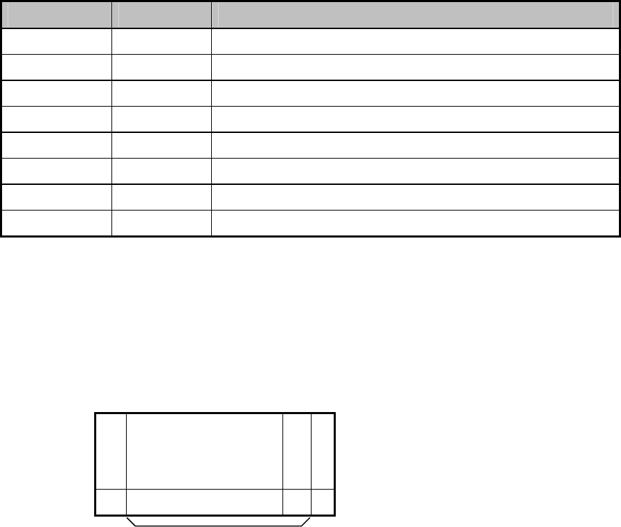
7.3.5. Test List
Test Category Detail
RFID Tag Reading Test
Red and Green LED lights flicker at the same time when RFID Tag is
presented within the read range.
Lights also flicker when same type of RFID Tag is presented within the
read rage.
Relay 1 Test
(Bargate trigger output) Relay is triggered when RFID Tag has been read.(1 Second)
Relay 2 Test
(Bargate trigger output) Relay is triggered when RFID Tag has been read. (1 Second).
Communication PORT Test When RFID TAG is recognized, Data is sent to the host using specified
communication format and protocol.
Sensor Test Red and Green LED lights flicker when sensor input has been detected.
8. Communication Protocol
PC는 회선(Circuit)이 접속된 RF Reader를 순차적(In ascending order) 또는 독립적으로
단말번호(어드레스)가 부여된(granted) 명령(command) 프레임(Frame)을 하고 단말번호(어드레스)에 의해
지정된 RF READER만 응답한다
If there is an error occurred in Command frame, RF Reader sends the negative response to the 응답 frame,
command frame is then retransmitted.
But, Link is Lost at Time Out (1 Second).
8.1. Transmission Control Code
Symbol Code Detail
SOH 01H Start Of Heading
STX 02H Start Of Text
ETX 03H End of Text
EOT 04H End Of Transmission
ENQ 05H Enquiry
ACK 16H Acknowledge
NAK 15H Negative Acknowledge
DLE 10H Circuit 절환
8.2. RFID TAG Reading Transmission Frame
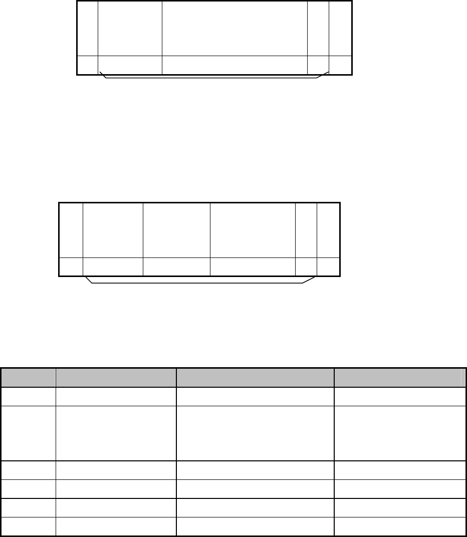
When the RFID Tag is decoded, it is tranmitted to the host using following transmission format.
(But, Host does not respond to the reader based upon RFID transmission)
If the communication setting dip switch 1 through 5 is all set to off position, number setting can not be done therefore
address is not assigned under the transmission frame.
S
T
X
TAG ID(Decimal Scale)
E
T
X
B
C
C
1 8 1 1
BCC Calculation limit
When the address for the communication setup is configured using the dip switch, the address is added into the
transmission frame.
S
T
X
(Address) TAG ID(Decimal Scale)
E
T
X
B
C
C
1 2 8 1 1
BCC Calculation limit
BCC Calculation limit: From STX to ETX -> XOR
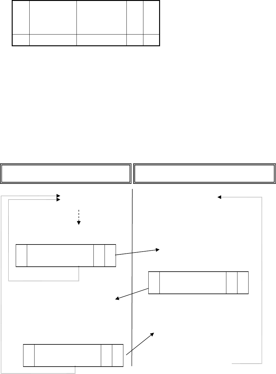
8.3. Command Request Frame (Host ÆReader)
S
T
X
(Address) (Command) Data
E
T
X
B
C
C
1 2 2 1 ~ 128 1 1
BCC Calculation limit
1).Reader Address: Reader address which has been set by the DIP switch(01 ~ 31 )
2).Command and Data :
Command Detail Data Remark
“01” ID Register(1 case) ID 16Byte(Decimal number display)
“02” ID Register(16 cases) ID 16Byte * 16 = 256Byte
(Decimal number display)
Empty space is filled up with
“0” to make 256 byte when
number count is below 16.
“03” ID Delete(1 case) ID 16Byte(Decimal number display)
“04” ID Delete All None
“10” Relay 1 Relay output None
“11” Relay 2 Relay output None
z command “02”will be updated in near future.
3). BCC Calculation limit: From STX to ETX -> XOR
8.4. Response Frame (Reader Æ Host)
Reader Address: Reader address which has been set by the DIP switch(01 ~ 31 )
Result : Handling the result for Command Request
“16”:
Acknowledge
“15”: Negative Acknowledge
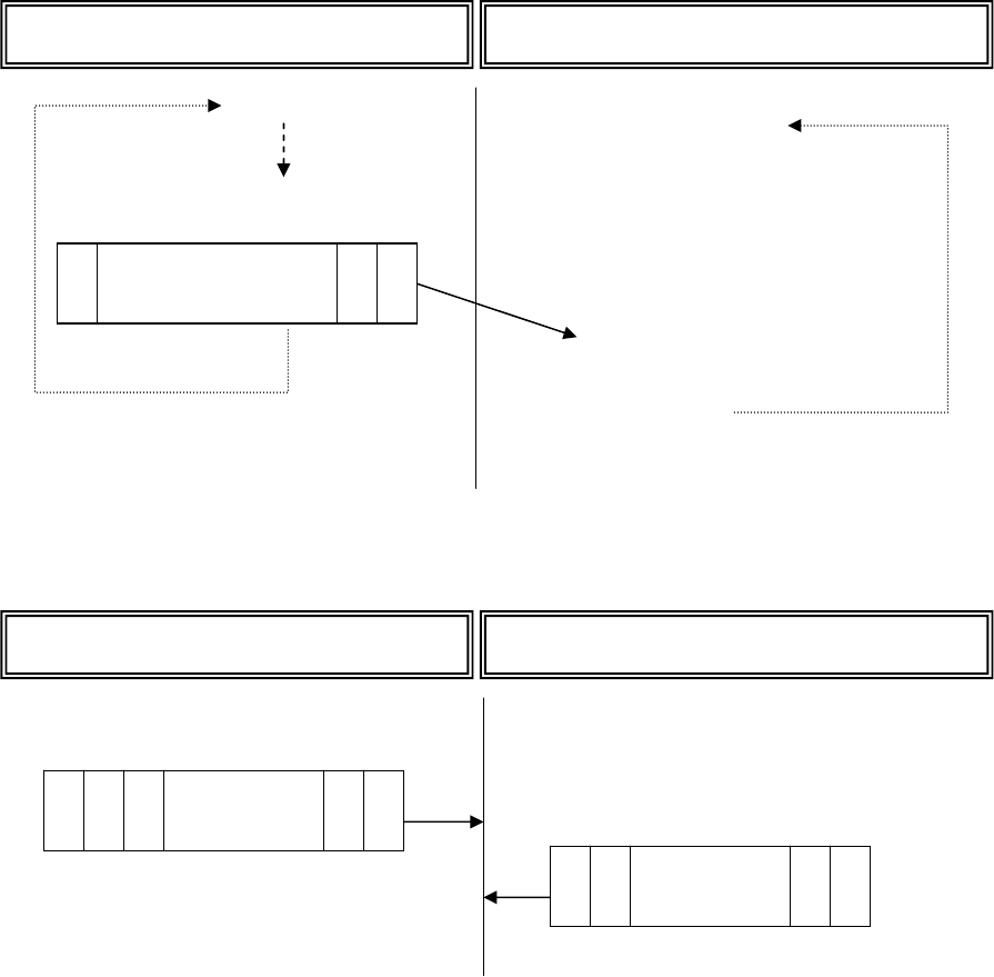
8.5. Transmission Order
8.5.1. Normal Operation: TAG is read during the TAG Reading Standby Mode,
Transmitted Valid TAG ID to the HOST
S
T
X
(Address) Result
E
T
X
B
C
C
1 2 2 1 1
RF READER HOST
S
T
X
TAG decoded data
E
T
X
B
C
C
S
T
X
Relay1 Relay output
command
E
T
X
B
C
C
Read mode in Standby
Decoded data is transmitted.
Valid decision
Rela
y
1 Rela
y
out
p
ut command
transmission
Relay1 Relay output
S
T
X
Response for
command
transaction
E
T
X
B
C
C
Standby on Transmission if positive
response is provided
Command is resent if ne
g
ative
res
p
onse is
p
rovided
Stand
y
on TAG decoded
data tranmission
8.5.2. Normal Operation: TAG is read during the TAG Reading Standby Mode,
Transmitted Invalid TAG ID to the HOST
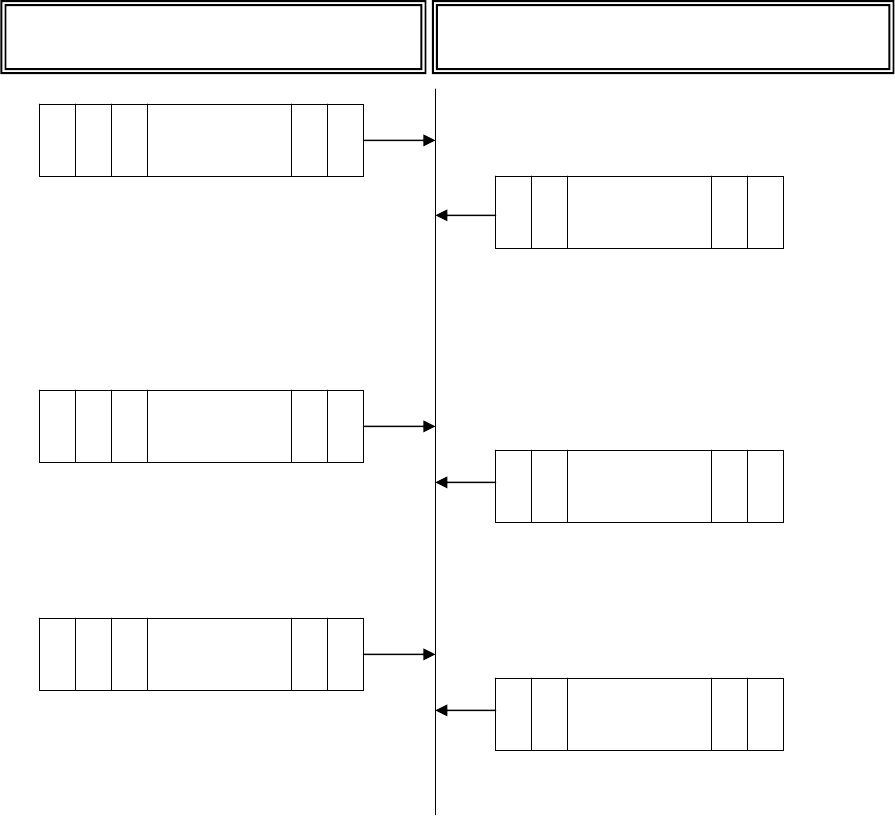
8.5.3. Positive Response after one Command Request Frame has been transmitted
RF READER HOST
S
T
X
TAG decoded data
E
T
X
B
C
C
Read mode in Standby
Transmission of Decoded Data
Invalid decision
Stand
y
on TAG decoded
data tranmission
HOST RF READER
S
T
X
Result ”16”
E
T
X
B
C
C
S
T
X
DATA
E
T
X
B
C
C
A
D
R
C
M
D
A
D
R
End after the result has been transmitted
End after the result (
p
ositive res
p
onse) has
been transmitted
8.5.4. Negative Response after one Command Request Frame has been transmitted
HOST RF READER
S
T
X
Result ”15”
E
T
X
B
C
C
S
T
X
DATA
E
T
X
B
C
C
A
D
R
C
M
D
A
D
R
S
T
X
DATA
E
T
X
B
C
C
A
D
R
C
M
D
Same Frame is retransmitted.
S
T
X
Result ”15”
E
T
X
B
C
C
A
D
R
Negative Response
S
T
X
DATA
E
T
X
B
C
C
A
D
R
C
M
D
Same Frame is retransmitted.
S
T
X
Result ”16”
E
T
X
B
C
C
A
D
R
Negative response
Positive Response.
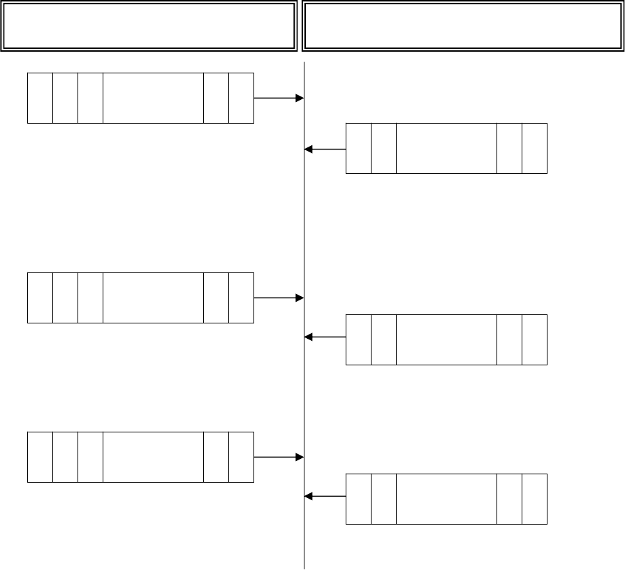
8.5.5. When many numbers of Command Request Frame have been transmitted
HOST RF READER
S
T
X
Result ”16”
E
T
X
B
C
C
S
T
X
DATA 1
E
T
X
B
C
C
A
D
R
C
M
D
A
D
R
S
T
X
DATA 2
E
T
X
B
C
C
A
D
R
C
M
D
S
T
X
Result ”16”
E
T
X
B
C
C
A
D
R
S
T
X
DATA 3
E
T
X
B
C
C
A
D
R
C
M
D
S
T
X
Result ”16”
E
T
X
B
C
C
A
D
R
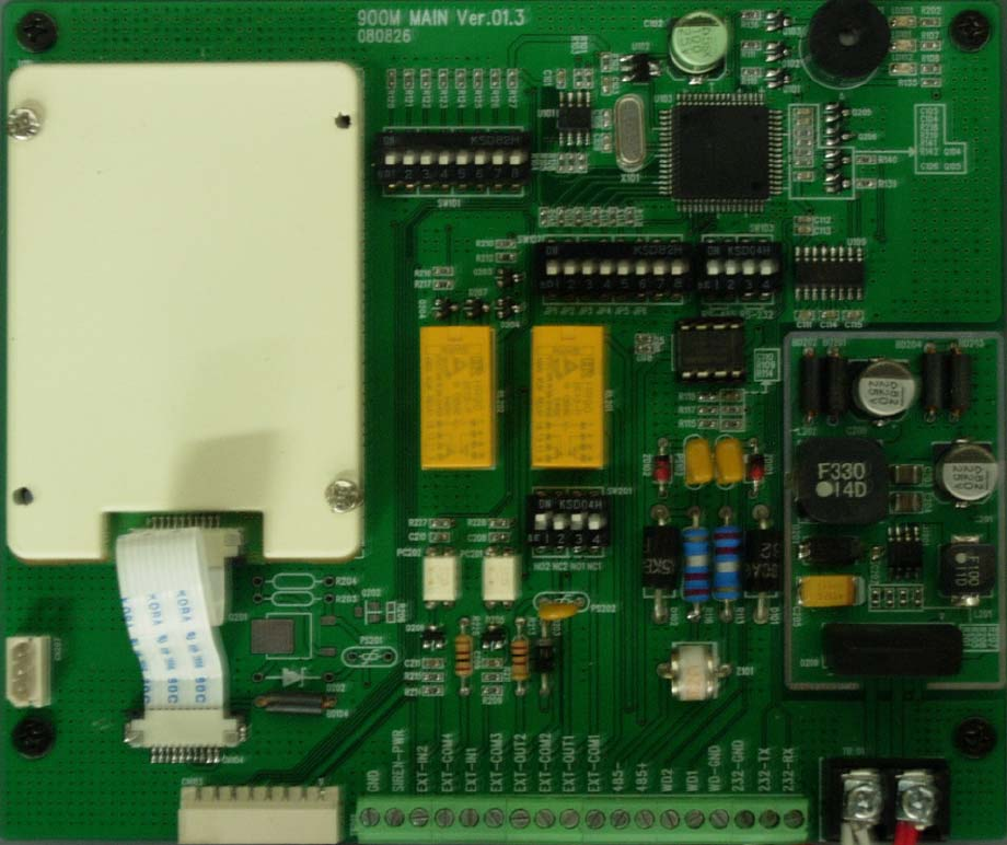
8.6. Product Image
8.6.1. MAIN PCB
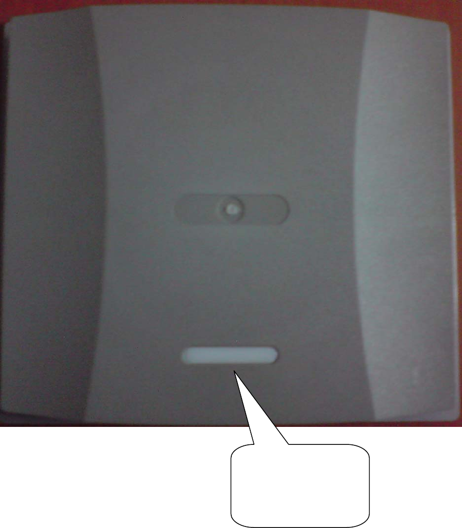
8.6.2. Frontal View
LED Display Screen
Normal : RED
TAG Scan: BLUE
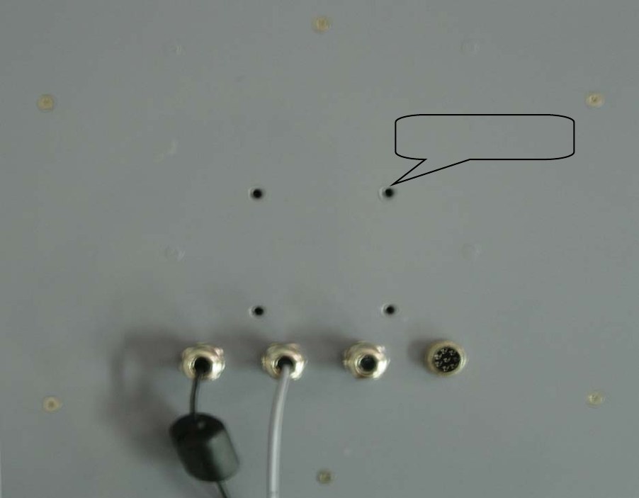
8.6.3. Rear View
Mounting Bracket Holes
CON4CON3CON2CON1
9. Product Installation
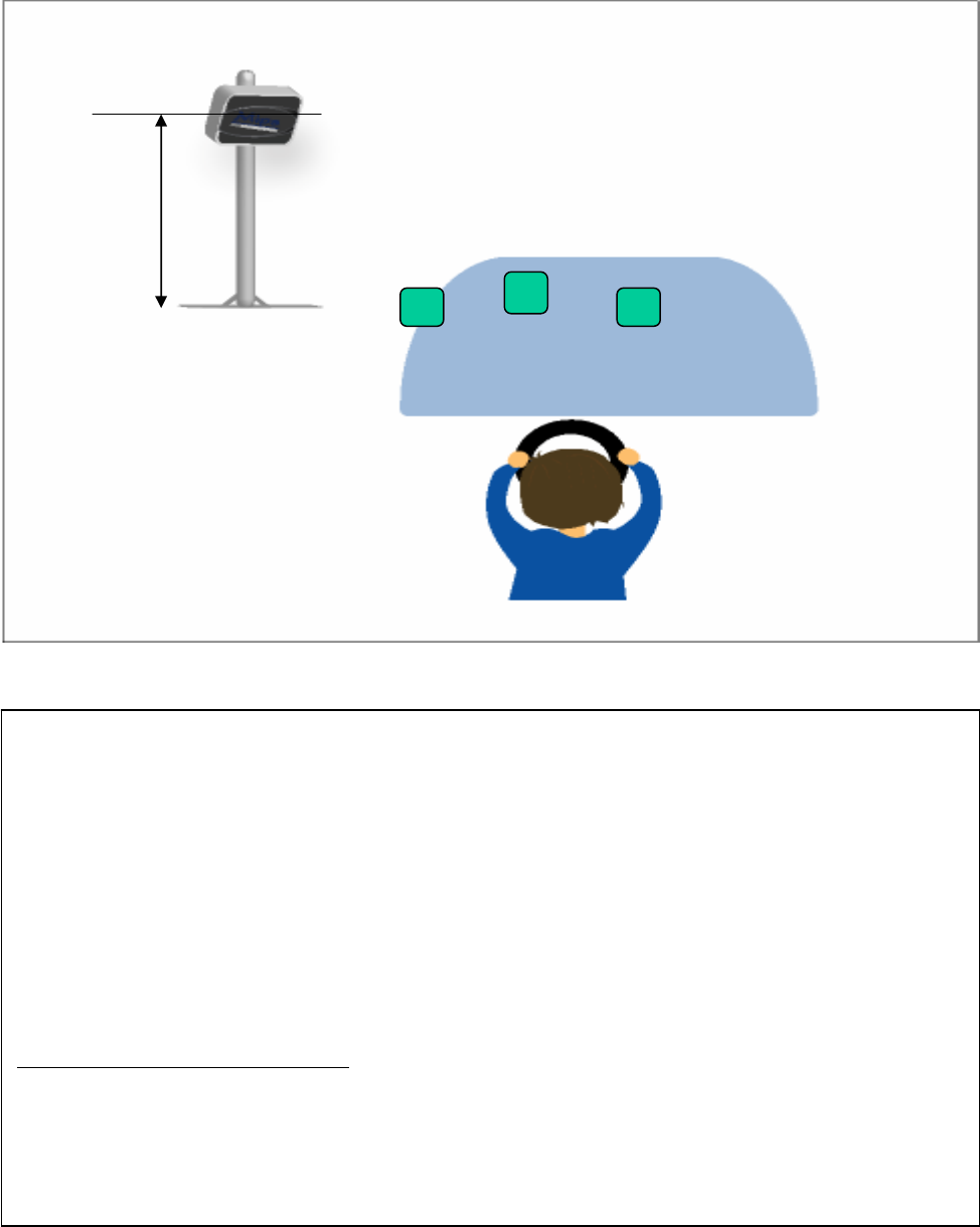
9.1. RFID TAG Positioning Area for the Vehicle
Vehicle RFID TAG Positioning Areas
170cm off from the ground
3
2 1
Based on RFID TAGs manufactured since Feb. 2006 (Vehicle model type is not related)
1. RF - Reader positioned in left side of the vehicle: Place RFID TAG at position 1.
2. RF - Reader positioned in right side of the vehicle: Place RFID TAG at position 2.
3. Reader positions are mixed as some left and some right based upon the entrance and the exit: Place RFID TAG at
position 3
(If the reading site is wide open area, position the card in vertical format at the opposite side (position 1 or 2) of
where the reader is positioned, or the mid position 3
Caution when positioning the RFID TAG
-RFID TAG must be 5cm away at both horizontally and vertically away from the vehicle metal frame..
-If top windshield area is tinted, do not position the RFID TAG to be in contact with more than 50% of the tint area.
-Place RFID TAG at the opposite side of where the reader is positioned.
9.2. Product Installation Location
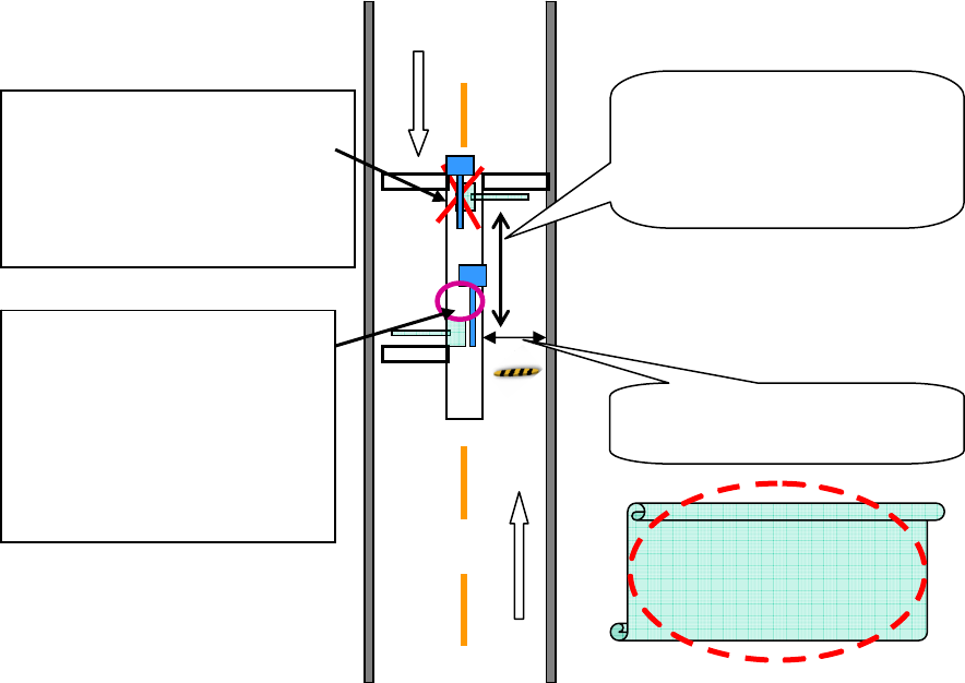
9.2.1. Installation location at the two lanes road with a center divider being present
Improper Installation
: Vehicle and bargate is too close to each
other
Proper Installation
: Reads RFID Tag within the speed
of 30Km/H
Height : 170cm from the ground
Distance between reader and the
bargate: 2.5m or more
Maximum road width: 3.5m
Entrance
Exit
Card location: Passenger’s side
windshield area towards the top
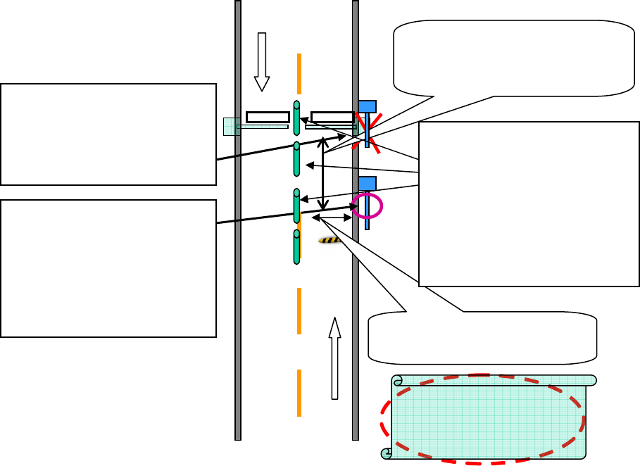
9.2.2. Installation location at the two lanes road without a center divider being present
Improper Installation
: Vehicle and bargate is too close to
each other
Proper Installation
: Reads RFID Tag within the speed
of 30Km/H
Height : 170cm from the ground
Distance between reader and the
bargate: 2.5m or more
Maximum road width: 3.5m
Entrance
Exit
Card location: Driver’s side
windshield area towards the top
Center Divider Installation:
In order to keep the certain distance
between the reader and the
vehicle, center divider is
needed to be installed
(up to front side of the reader)
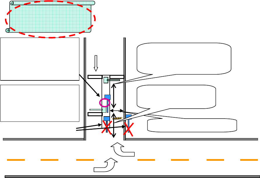
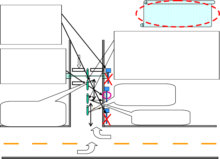
9.2.3. Installation location at the T type intersection where a center divier is located at
the entrance
Improper Installation:
depending on the location A or
B, only one will be verified
A
Proper Installation:
A and B locations are both OK
Height : 170cm from the ground
Distance between reader and the
bargate: 2.5m or more
Maximum road width: 3.5m
Exit
Card location: Passenger’s side
windshield area towards the top
Reader installation location
:At least 4m away
Entrance
9.2.4. Installation location at the T type intersection without a center diviers being
present
Reader installation location
:At least 4m away
Improper Installation
: depending on the location A
or B, only one will be verified
A
Proper Installation:
location A , B does not matter
Height : 170cm from the ground
Distance between the reader &
the gate: at least 2.5m Maximum road width: 3.5m
Exit
Card location: Driver’s side
windshield area towards the top
Center Divider Installation:
In order to keep the certain distance between the
reader and the vehicle, center divider is
needed to be installed
(up to front side of the reader)
Entrance
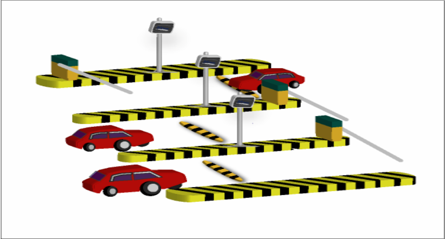
9.2.5. General Installation tip for all the other cases
For all other cases, please verify the installation area prior to setup.
Bargate and Reader (transmission distance) :2.5~3M
Ramp : 1M away from the Reader