U Line Refrigerator 2115R Users Manual Front_Cover_30131
2275DWRWOL to the manual 91aa2817-4b4e-4df2-8ef6-9a5136ae0ccb
2015-02-04
: U-Line U-Line-U-Line-Refrigerator-2115R-Users-Manual-391286 u-line-u-line-refrigerator-2115r-users-manual-391286 u-line pdf
Open the PDF directly: View PDF ![]() .
.
Page Count: 180 [warning: Documents this large are best viewed by clicking the View PDF Link!]
- Section 3 Service and Repair.pdf
- Operation
- Figure 1 . CLR2160
- Troubleshooting (continued)
- 1. Ice Making and Refrigeration (Figure 2).
- 2. Ice Making and No Refrigeration (Figure 3).
- 3. Refrigeration and No Ice Making (Figure 4).
- 4. Ice Harvest/Water fill (No Refrigeration Possible) (Figure 5).
- 5. Off (Figure 6).
- 6. Water Fill - No Refrigeration (Figure 7).
- 7. Cleaning (No Refrigeration Possible) (Figure 8).
- Figure 2 . CLRCO2175 Mode 1: Ice Making and Refrigeration
- Figure 3 . CLRCO2175 Mode 2: Ice Making and No Refrigeration (or Ref Defrost)
- Figure 4 . CLRCO2175 Mode 3: Refrigeration and No Ice Making
- Figure 5 . CLRCO2175 Mode 4: Ice harvest (No Refrigeration Possible)
- Figure 6 . CLRCO2175 Mode 5: Off
- Figure 7 . CLRCO2175 Mode 6: Water Fill - No Refrigeration Possible (Normal Start-Up)
- Figure 8 . CLRCO2175 Mode 7: Cleaning (No Refrigeration Possible)
- Figure 9 . 2175R/2115R/2175WC/2175BEV/2275DWRR/2175DWRR
- Figure 10 . 2275DWRWS/2275ZWC
- Figure 11 . Frost Free Refrigeration System.
- Figure 12 . CO2175R & 2175RF Only: Typical Frost Free Airflow Configuration
- Ice maker
- Figure 13 . CO2175F Harvest-1 Cycle (First 30 Seconds
- Figure 14 . CO2175F Harvest-2 Cycle (After 30 Seconds)
- Figure 15 . CO2175F Harvest-3 Cycle (Post Harvest)
- Figure 16 . CO2175F Water Fill Cycle
- Figure 17 . CO2175F Freeze Cycle
- Figure 18 . CO2175/2275DWR Harvest-1 Cycle (First 30 Seconds)
- Figure 19 . CO2175/2275DWR Harvest-2 Cycle (After 30 Seconds)
- Figure 20 . CO2175/2275DWR Harvest-3 Cycle (Post Harvest)
- Figure 21 . CO2175/2275DWR Water Fill Cycle
- Figure 22 . CO2175/2275DWR Freeze Fill Cycle
- Figure 23 . 1175R/1115R/1175WC//1115WC1175BEV/ADA24R Normal Vapor/Compression Cycle
- Échelon Electronic Control
- 1. Hold the desired key ensuring the light above the key is lit.
- 2. Press the other key three times, ensuring it lights up each time.
- 3. Release the held key only after releasing the pressed key for the third time.
- Adjusting the Set-point - 2275DWRWS Only
- 2. While the top or bottom bar of the F in °F is flashing, press the WARMER or COOLER icon as required to adjust the set-point temperature. The change will be set five seconds after adjusting the temperature and the new set-point temperature will be...
- Figure 24 . Adjusting Set-Point Temperature-2275ZWC/ 2275ZWCOL
- 1. Press and release the desired zone WARMER icon to put the controller in the SET TEMPERATURE mode. The current range symbol will show on the display (top, Figure 24).
- 2. Press the WARMER or COOLER icon to scroll to the desired range (RW, WW, SW, BV).
- 3. When the desired range is displayed, press the LIGHT icon to display the current set-point temperature (bottom, Figure 24).
- 4. When the decimal is flashing, press the WARMER or COOLER icon as required to adjust the set-point temperature.
- 5. When the desired set-point is displayed, press the LIGHT icon. The new set-point will show in the display.
- 6. Repeat for other zone display if required.
- Viewing Actual Temperature - 2275DWRWS Only
- 1. Press and hold the WARMER icon for the desired zone for approximately five seconds until unit beeps, and release when the decimal in the display begins to flash (Figure 25).
- 2. The display will show the actual zone temperature.
- 3. After five seconds, the display will return to the set-point temperature.
- Figure 25 . Displaying Zone Temperature
- Forced Defrost
- 1. Plug in unit.
- 2. The display may show a SP or --, either is OK.
- 3. Install a jumper on J3. The jumper can be obtained from U-Line P/ N 68080.
- 4. Hold down WARMER, COLDER and LIGHT buttons until display shows model number and main board beeps.
- 5. Use WARMER/COLDER to select new model number.
- 6. Press and release LIGHT key.
- 7. Wait for display to stop flashing.
- 8. Remove jumper from board.
- 9. Unplug unit and wait five seconds.
- 10. Plug unit back in.
- 5. Compressor runtime based on last cycle
- 10. Adjust thermistor 1 offset—10 to +10F
- 18. Adjust thermistor 4 offset
- 23. Defrost interval adjust. 3 to 24 hours
- Model
- Part Number
- PIN 7 C_FAN
- PIN 6 LIGHTS
- PIN 5
- PIN 4 H_H2O
- PIN 3 C_PUMP
- PIN 2 R_VALVE
- PIN 1 BP_VALVE
- Relay 1
- Relay 2
- Relay 3
- Relay 4
- Relay 5
- Relay 6
- Relay 7
- Model
- Thermistor 1
- Thermistor 2
- Thermistor 3
- Thermistor 4
- Door Switch 1
- Door Switch 2
- Échelon Service Quick Reference Card
- Échelon Electronic Control Quick Reference Guide
- Origins Electronic Control
- 1. Hold the desired key.
- 2. Press the other key three times.
- 3. Release the held key only after releasing the touched key for the third time.
- Viewing Actual Temperature
- 3. Error log
- Origins Electronic Control Quick Reference Guide
- Refrigeration System Diagnosis Guide
- CO2175F/2175RF/CO2175DWR
- Figure 29 . CO2175F/2175RF/CO2175DWR
- Figure 30 . Ice Maker Limit Switch-Normally Closed
- 1175R/1115R 1175WC/1115WC 1175BEV/ADA24R
- The U-Line ADA24R models employ both a 12VDC evaporator fan assembly and condenser fan assembly. The motors are powered by a 12VDC power supply located in the base of the unit. These fans are designed to operate in conjunction with the compressor and...
- Origins Electronic Control Quick Reference Guide
- Adjustments and Repair
- 1. Use a level to check the unit from front to back (Figure 33) and from side to side (Figure 34).
- 2. If the unit is not level, adjust the feet on the corners as necessary (Figure 35). Rotating the feet clockwise raises the unit.
- Figure 32
- Figure 33
- Figure 34
- Figure 35
- Figure 36
- Figure 37
- Figure 38
- Figure 39
- Figure 40
- 4. Mount the door to recheck alignment and repeat steps 2 and 3 if further adjustment is necessary.
- 5. When top edge of door is parallel to top edge of cabinet, remove the door and ensure the two screws are secure.
- 6. Remove the door closers from the bottom hinge, clean thoroughly and lubricate the mating surfaces with petroleum jelly.
- 7. Reinstall the closers, lining up the bosses with holes in hinge and hinge plate (Figure 41).
- Figure 41
- 8. Mount the door, install top hinge pivot pin.
- 1. Carefully examine the door’s gasket to assure that it is firmly in contact with the cabinet.
- 2. If the door is properly aligned, no further adjustment is necessary. If it is not, use the following procedure.
- 1. Loosen (do not remove) top and bottom hinge screws (Figure 42 and Figure 43).
- Figure 42
- Figure 43
- Figure 44
- Figure 45
- Side-to-Side Adjustment
- Top-to-Bottom (and Left-to-Right) Adjustment
- Figure 52
- Figure 53
- 4. Repeat the procedure with the other slide if necessary.
- 1. Remove one slide’s mounting screws.
- 2. Reposition the slide so it is the same distance from the bottom of the liner as the other slide. Measure to confirm.
- 3. Mark new drilling holes using different sets of mounting holes on the slide (Figure 54).
- Figure 54
- Figure 55
- Ice Cube Thickness Adjustment
- 1. To enter the thickness adjustment mode:
- 2. The factory setting is “0,” and the total range of adjustment is -5 to +5 (ideal range is -1 to +1). Use the UP ARROW button to raise the setting and thicken the ice bridge, or the DOWN ARROW button to lower the setting to thin the ice bridge.
- 3. Touch and release the LIGHT button key to exit the ice thickness adjustment mode.
- 4. Remove all ice from the storage bin.
- Figure 56
- Figure 57
- 1. Disconnect unit from power source.
- 2. Remove two screws (Figure 58) from fan cover.
- 3. Remove two screws holding fan bracket to liner.
- 4. Unplug fan connection.
- 5. Remove two nuts holding the fan to the fan bracket.
- 6. Replace with new fan.
- 7. Plug in the fan connection.
- 8. Reinstall fan bracket to liner, making sure the fan wires are tucked behind the fan bracket.
- 9. Reinstall unit and test.
- 1. Disconnect unit from power source.
- 2. Remove two screws (Figure 58) from fan cover.
- 3. Remove three screws from evaporator cover.
- 4. To remove, pull evaporator cover forward and turn.
- Figure 58 . CO2175F/2175RF
- Replacing Evaporator Fan Motor - CO2175DWR
- 1. Disconnect unit from power source.
- 2. Remove two screws (Figure 58) holding evaporator fan cover to evaporator cover.
- 3. Unplug fan connection.
- 4. Remove two nuts and two washers holding the fan to the fan bracket.
- 5. Replace with new fan.
- 6. Plug in the fan connection, making sure the fan wires are tucked behind the fan bracket.
- 7. Reinstall evaporator cover.
- 8. Reinstall unit and test.
- 9. Reinstall fan bracket to liner, making sure the fan wires are tucked behind the fan bracket.
- 10. Reinstall unit and test.
- 1. Disconnect unit from power source.
- 2. Remove two screws (Figure 58) holding evaporator cover to drain pan.
- 3. Remove two screws holding evaporator to drain pan.
- 4. Remove two screws holding fan bracket to drain pan.
- 5. Unplug fan connection.
- 6. Reinstall parts in reverse order.
- 7. Reinstall unit and test.
- Figure 59 . CO2175DWR
- Replacing Ice Maker
- 1. Unplug unit.
- 2. Disconnect ice maker wire harness at plug (Figure 60).
- 3. Disconnect thermistor plug.
- 4. Remove water inlet tube.
- 5. Remove front cover.
- 6. Advance ejector blade to the 3 o’clock position by turning the 5/ 16" hex head on the small brass gear counterclockwise.
- 7. Remove three screws from wall of freezer housing.
- 8. Remove ice maker assembly.
- 9. Install new ice maker assembly.
- 10. Reconnect plug.
- 11. Reconnect thermistor plug.
- 12. Insert water inlet tube.
- 13. Apply Permagum® to all exit holes.
- 14. Install back panel.
- 15. Plug in unit and test.
- Figure 60
- Replacing Mold and Heater - CO2175F/CO2175DWR
- 1. Remove ice maker assembly. Refer to Replacing Ice Maker Assembly.
- 2. Remove one stripper screw (Figure 61) and stripper.
- 3. Remove three face plate screws and face plate.
- 4. Remove one screw and detach limit switch from mold.
- 5. Detach heater leads.
- 6. Remove two screws and mold from support housing.
- 7. To assemble, replace parts in reverse order.
- 8. Install the ice maker assembly.
- Figure 61
- Plumbing - CLR2160 and CLRCO2175
- Figure 62
- Figure 63
- Figure 64
- Figure 65
- Figure 66
- Figure 67
- Figure 68
- 5. Place a suitable container beneath the pump’s discharge tube. (The bucket must be able to hold a minimum of one gallon.)
- 6. Plug the ice maker power cord into a properly grounded, polarized electrical outlet.
- 7. Verify pump operation by pouring one gallon of water into the ice storage bin of the ice maker. The pump should energize and pump the water into the container.
- 8. At this time, verify that all tube and clamp connections are tight and leak free.
- 9. Unplug unit power cord from electrical outlet.
- 10. Reinstall back panel.
- 1. Attach the 5/8" ID drain connection on the back of the unit to a 5/8" OD rigid tube, using a worm clamp.
- 2. Attach the other end of the rigid tube to your 5/8" ID drain line with a worm clamp.
- 3. Insulate the drain line, if necessary, to prevent condensation.
- 1. Locate the desired cold water supply location. Attach a 1/4" copper line to this location and route the tubing to the appliance. Leave approximately 8' of water line to be coiled behind the appliance as shown (Figure 69). This water line should be...
- Figure 69
- Figure 70
- 3. Your U-Line icemaker requires a drain connection. This unit can be purchased with or without a factory-installed drain pump. If a pump is not installed in the appliance you must use the gravity drain style installation OR install a pump per the in...
- 4. Slide two hose clamps onto the drain connection on the rear of the appliance. Insert the barbed fitting half-way into this connection. On the other end of the barbed fitting attach the 5/8" braided tubing. Slide a clamp onto each side of the barbe...
- Figure 71
- Figure 72
- 5. Determine the location of your drain and begin to route the drain tubing in that direction. If using the gravity drain option you must provide 1/4" drop every foot of line. For drain pump application you must not go higher than 10 feet of lift. Th...
- 6. Connect the water supply fitting by screwing the brass garden hose fitting to the water valve in the rear of the unit. Tighten this fitting with a pliers. Do not use Teflon tape or joint compound on the fitting. The rubber washer provides an adequ...
- 7. Plug in the unit and put the unit into OFF mode by holding the power key for 10 seconds. Not doing this will cause the unit to fill with water for three minutes.
- 8. Turn on the water supply and ensure the connections are free of leaks.
- 9. Begin to push the appliance into the desired cabinet opening. The copper tubing should remain in two coils behind the unit. While pushing the unit into the opening continuously reroute the drain tube to avoid kinks. The most common installation pu...
- Plumbing - CLR2160 and CLRCO2175
- 10. Once pushed completely into the opening finish routing the drain tubing to the desired location. Common installations use a floor drain, standpipe, garbage disposal, or Y-branch tailpiece-type drain connection (Figure 73 - 76). After the installa...
- 11. For the gravity/floor drain or the standpipe drains it is important to secure the drain tubing to those items to prevent it from coming loose. For the disposal or Y-branch tailpiece connections press the drain tube over the barbed end on the conn...
- 12. After all connections have been completed turn the unit to the ON position. Pour one gallon of water into the ice bin and check all drain connections for leaks. During this time also ensure that the water flows from the bin. If the water does not...
- Figure 73
- Figure 74
- Figure 75
- Figure 76
- Water Supply Connection
- If using the flexible water supply kit, follow the instructions included with the kit.
- 2. Locate the U-Line supplied garden hose fitting. Ensure the end of the copper tubing has been cut straight and free of burrs. Slide the compression nut and ferrule onto the copper tubing as shown (Figure 78). Push the assembly completely into the t...
- Section 4 Parts 1_10.pdf
- Parts Listing
- 1. Refer to Service Parts and locate the illustration(s) for the model you are servicing.
- 2. Locate the desired part to be serviced and note the item number assigned to it.
- 3. Locate the item number within the parts list. Note the full description and the corresponding part number. If this is for a warranty unit, indicate and record the model and serial numbers.
- 4. When ordering parts, it will be necessary to supply Model Number, Serial Number, Part Number, Part Description and in some cases Color or Voltage.
- 5. U-Line requires the return of the parts listed below if replaced under warranty.
- Our warranty records may not match the customer's information. In this case, a proof of purchase will be required. If you do not have the proof of purchase at the time the order is placed, the part will be sent net 15 days, charged to a Visa or Maste...
- Item Part No. Part No. Part No. Description Black White Stainless Steel
- Item Part No. Part No. Description Black Stainless Steel
- Item Part No. Part No. Description Black Stainless Steel
- 2275DWRWS/2275DWRWOL (2 of 2)
- 2275DWRWS/2275DWRWOL (2 of 2)
- CO2175F (1 of 4)
- CO2175F (1 of 4)
- CO2175F (2 0f 4)
- CO2175F (2 of 4)
- CO2175F (3 of 4)
- CO2175f (3 of 4)
- CO2175F (4 of 4)
- CO2175F (4 of 4)
- 2175RF (1 of 3)
- 2175RF (1 of 3)
- 2175RF (2 of 3)
- 2175RF (2 of 3)
- 2175RF (3 of 3)
- 2175RF (3 of 3)
- CO2275DWR (1 of 4)
- CO2275DWR (1 of 4)
- CO2275DWR (2 of 4)
- CO2275DWR (2 of 4)
- CO2275DWR (3 of 4)
- CO2275dWR (3 of 4)
- CO2275DWR (4 of 4)
- CO2275dWR (4 of 4)
- 2275ZWC/2275ZwCOL (1 of 3)
- 2275ZWC/2275ZWCOL (1 of 3)
- 2275ZWC/2275ZwCOL (2 of 3)
- 2275ZWC/2275ZWCOL (2 of 3)
- 2275ZWC/2275ZWCOL (3 of 3)
- 2275ZWC/2275ZWCOL (3 of 3)
- 1175R (1 of 2)
- 1175R (1 of 2)
- 1175R (2 of 2)
- 1175R (2 of 2)
- 1115R (1 of 2)
- 1115R (1 of 2)
- 1115R (2 of 2)
- 1115R (2 of 2)
- 1175WC (1 of 2)
- 1175WC (1 of 2)
- 1175WC (2 of 2)
- 1175WC (2 of 2)
- 1115WC (1 of 2)
- 1115WC (1 of 2)
- 1115WC (2 of 2)
- 1115WC (2 of 2
- 1175BEV (1 OF 2)
- 1175BEV (1 of 2)
- 1175bev (2 OF 2)
- 1175BEV (2 of 2)
- This page intentionally left blank.
- Item Part No. Part No. Part No. Description Black White Stainless Steel
- Item Part No. Part No. Part No. Description Black White Stainless Steel
- Item Part No. Part No. Part No. Description Black White Stainless Steel
- Item Part No. Part No. Part No. Description Black White Stainless Steel
- Item Part No. Part No. Part No. Description Black White Stainless Steel
- Item Part No. Part No. Description Overlay Stainless Steel
- Item Part No. Part No. Description Overlay Stainless Steel
- Item Part No. Part No. Part No. Description Black White Stainless Steel
- Item Part No. Part No. Description Black Stainless Steel
- Item Part No. Part No. Description Black Stainless Steel
- Item Part No. Part No. Description Black Stainless Steel
- Item Part No. Part No. Description Black Stainless Steel
- 2275DWRWS/2275DWRWOL (1 of 2)
- 2275DWRWS/2275DWRWOL (2 of 2)
- CO2175F (1 of 4)
- CO2175F (1 of 4)
- CO2175F (2 0f 4)
- CO2175F (2 of 4)
- CO2175F (3 of 4)
- CO2175F (3 of 4)
- CO2175F (4 of 4)
- CO2175F (4 of 4)
- 2175RF (1 of 3)
- 2175RF (1 of 3)
- 2175RF (2 of 3)
- 2175RF (2 of 3)
- 2175RF (3 of 3)
- 2175RF (3 of 3)
- 2175RF (3 of 3)
- CO2175DWR/CO2275DWR (1 of 4)
- CO2175DWR/CO2275DWR (1 of 4)
- CO2175DWR/CO2275DWR (2 of 4)
- CO2175DWR/CO2275DWR (2 of 4)
- CO2175DWR/CO2275DWR (3 of 4)
- CLR2160 (1 of 2)
- CLR2160 (1 of 2)
- 2115WC/2115WCOL/2115WCOL2 (1 of 2)
- 2115WC/2115WCOL/2115WCOL2 (2 of 2)
- 2175BEV/2175BEVOL/2175BEVOL2 (1 of 2)
- 2175BEV/2175BEVOL/2175BEVOL2 (2 of 2)
- 2175DWRR/2275DWRR (1 of 2)
- CO2175DWR/CO2275DWR (3 of 4)
- CO2275DWR (4 of 4)
- CO2275DWR (4 of 4)
- 2275ZWC/2275ZWCOL (1 of 3)
- 2275ZWC/2275ZWCOL (1 of 3)
- 2275ZWC/2275ZWCOL (2 of 3)
- 2275ZWC/2275ZWCOL (2 of 3)
- 2275ZWC/2275ZWCOL (3 of 3)
- 2275ZWC/2275ZWCOL (3 of 3)
- 1175R (1 of 2)
- 1175R (1 of 2)
- 1175R (2 of 2)
- 1175R (2 of 2)
- 1115R (1 OF 2)
- CLRCO2175 (1 of 4)
- 1115R (1 OF 2)
- 1115R (2 of 2)
- 1115R (2 of 2)
- 1175WC (1 of 2)
- 1175WC (1 of 2)
- 1175WC (2 of 2)
- 1175WC (2 of 2)
- 1115WC (1 of 2)
- 1115WC (1 of 2)
- 1115WC (2 of 2)
- 2175DWRR/2275DWRR (2 of 2)
- CLRCO2175 (2 of 4)
- CLRCO2175 (3 of 4)
- Item Part No. Part No. Description
- 2175BEV/2175BEVOL/2175BEVOL2 (1 of 2)
- 2175BEV/2175BEVOL/2175BEVOL2 (2 of 2)
- 2175DWRR/2275DWRR (1 of 2)
- 2275DWRWS/2275DWRWOL (2 of 2)
- 2275DWRWS/2275DWRWOL (2 of 2)
- CO2175F (1 of 4)
- CO2175F (1 of 4)
- CO2175F (2 0f 4)
- CO2175F (2 of 4)
- CO2175F (3 of 4)
- CO2175f (3 of 4)
- CO2175F (4 of 4)
- CO2175F (4 of 4)
- 2175RF (1 of 3)
- 2175RF (1 of 3)
- 2175RF (2 of 3)
- 2175RF (2 of 3)
- 2175RF (3 of 3)
- 2175RF (3 of 3)
- CO2275DWR (1 of 4)
- CO2275DWR (1 of 4)
- CO2275DWR (2 of 4)
- CO2275DWR (2 of 4)
- CO2275DWR (3 of 4)
- CO2275dWR (3 of 4)
- CO2275DWR (4 of 4)
- CO2275dWR (4 of 4)
- 2275ZWC/2275ZwCOL (1 of 3)
- 2275ZWC/2275ZWCOL (1 of 3)
- 2275ZWC/2275ZwCOL (2 of 3)
- 2275ZWC/2275ZWCOL (2 of 3)
- 2275ZWC/2275ZWCOL (3 of 3)
- 2275ZWC/2275ZWCOL (3 of 3)
- 1175R (1 of 2)
- 1175R (1 of 2)
- 1175R (2 of 2)
- 1175R (2 of 2)
- 1115R (1 of 2)
- 1115R (1 of 2)
- 1115R (2 of 2)
- 1115R (2 of 2)
- 1175WC (1 of 2)
- 1175WC (1 of 2)
- 1175WC (2 of 2)
- 1175WC (2 of 2)
- 1115WC (1 of 2)
- 1115WC (1 of 2)
- 1115WC (2 of 2)
- 1115WC (2 of 2
- 1175BEV (1 OF 2)
- 1175BEV (1 of 2)
- 1175bev (2 OF 2)
- 1175BEV (2 of 2)
- This page intentionally left blank.
- CLRCO2175 (4 of 4)
- 2175R (1 of 2)
- CLR2160 (2 of 2)
- 2115R (2 of 2)
- 2115R (2 of 2)
- 2175WC/2175WCOL/2175WCOL2 (1 of 2)
- 2175WC/2175WCOL /2175WCOL2(2 of 2)
- 1115WC (2 of 2
- 1175BEV (1 OF 2)
- Item Part No. Part No. Part No. Description Black White Stainless Steel
- Item Part No. Part No. Part No. Description Black White Stainless Steel
- Item Part No. Part No. Part No. Description Black White Stainless Steel
- Item Part No. Part No. Part No. Description Black White Stainless Steel
- CLR2160 (2 of 2)
- CLRCO2175 (4 of 4)
- 2175R (1 of 2)
- 2175R (2 of 2)
- 2115R (1 of 2)
- 2175WC/2175WCOL/2175WCOL2 (1 OF 2)
- 2175WC/2175WCOL /2175wcol2(2 of 2)
- 2115WC/2115WCOL/2115WCOL2 (1OF2)
- 2115WC/2115WCOL/2115WCOL2 (2 of 2)
- 2175BEV/2175BEVOL/2175BEVOL2 (1 OF 2)
- 2175BEV/2175BEVOL/2175BEVOL2 (2 OF 2)
- 2175DWRR/2275DWRR (1 OF 2)
- 2175DWRR/2275DWRR (2 of 2)
- Parts Listing
- Section 5 Wiring Diagrams Jan 2010.pdf
- Section 1 General Information.pdf
- Three generations of pride and quality manufacturing and design improvements are built into all U-Line products. The result: U-Line leads the market with innovative technology and superior craftsmanship.
- This manual contains specific instructions for servicing the U-Line Products which include these models:
- 2115R
- 2115WC
- 2115WCOL
- 2275DWRR
- 2175R
- 2175RF
- 2175WC
- 2175WCOL
- CLR2160
- CLRCO2175
- CO2275DWR
- CO2175F
- 2175BEV
- 2275DWRWS
- 2275DWRWS
- 2275ZWC
- 2275ZWCOL
- 1115R
- 1115WC
- 1175BEV
- 1175R
- 1175WC
- ADA24R
- This service manual has been written to cover products manufactured with HFC-134A. HFC-134A compressors receive a synthetic based ester oil charge. The hygroscopic (water attraction) property of ester oil is many times greater than the mineral oils p...
- Cleanliness of the system is extremely important. The presence of residues (chlorinated or greasy residues, mineral oil, or impurities) can lead to capillary tube restrictions, oil return problems and compressor damage. Do not use flux on brazed joints.
- SECTION 1 - GENERAL INFORMATION
- Introduction 1-1
- Potential Problems With HFC-134A 1-1
- Safety Precautions 1-4
- Safety Alert Definitions 1-4
- General Precautions 1-4
- U-Line Corporation Limited Warranty 1-5
- Product Liability Policy 1-6
- Serial Number Format 1-7
- Warranty Claims Procedure 1-7
- Proof of Purchase 1-7
- Parts Listing 1-8
- SECTION 2 - TROUBLESHOOTING
- Customer Call Guide 2-1
- Refrigeration System Diagnosis Guide 2-3
- Thermistor Types 2-3
- Troubleshooting 2-4
- SECTION 3 - SERVICE AND REPAIR
- Operation 3-1
- CLR2160 3-1
- Operating Environmental/Climate Control Requirements 3-29
- For All - Except WC, DWRWS, BEV Center, CODWR & 2275ZWC/2275ZWCOL 3-29
- For WC, DWRWS, CODWR, BEV, CLRCO & 2275ZWC/2275ZWCOL 3-29
- Échelon Keypad Options 3-29
- Échelon Service Menu 3-32
- Error Codes 3-34
- Origins Electronic Control 3-38
- Origins Keypad Options 3-38
- Origins Service Menu 3-39
- Defrost Information - All models 3-41
- Specifications 3-42
- CLR2160 3-42
- Adjustments and Repair 3-47
- Leveling 3-47
- Door Alignment - Échelon Models 3-47
- Door Alignment - Origins Models 3-49
- Drawer Alignment 3-49
- Ice Cube Thickness Adjustment 3-53
- Parts Replacement 3-54
- Plumbing - CLR2160 and CLRCO2175 3-57
- SECTION 4 - PARTS
- Parts Listing 4-1
- Anti-Tip Kit 4-1
- CLR2160 4-2
- CLRCO2175 4-6
- 2175R 4-14
- 2115R 4-18
- 2175WC/2175WCOL 4-22
- 2115WC/WCOL 4-26
- 2175BEV 4-30
- 2275DWRR 4-34
- 2275DWRWS/2275DWRWOL 4-38
- CO2175F 4-42
- 2175RF 4-50
- CO2175DWR 4-56
- 2275ZWC/2275ZWCOL 4-64
- 1175R 4-70
- 1115R 4-74
- 1175WC 4-78
- 1115WC 4-82
- 1175BEV 4-86
- ADA24R 4-90
- SECTION 5 - WIRING DIAGRAMS
- CLRCO2175 5-1
- 2175DWRR 5-3
- 2175RF 5-3
- CO2175F 5-4
- CO2175DWR 5-4
- U-Line Corporation Limited Warranty
- U-Line Corporation warrants each U-Line product to be free from defects in materials and workmanship for a period of one year from the date of purchase; and warrants the sealed system (consisting of the compressor, the condenser, the evaporator, the ...
- The following are excluded from this limited warranty: installation charges; damages caused by disasters or acts of God, such as fire, floods, wind and lightening; damages incurred or resulting from shipping, improper installation, unauthorized modif...
- If a product defect is discovered during the applicable warranty period, you must promptly notify either the dealer from whom you purchased the product or U-Line at P.O. Box 245040, Milwaukee, Wisconsin 53224 or at 414-354-0300. In no event shall suc...
- This limited warranty is in lieu of any other warranty, express or implied, including, but not limited to any implied warranty of merchantability or fitness for a particular purpose; provided however, that to the extent required by law, implied warra...
- Some states do not allow limitations on how long an implied warranty lasts or the exclusion or limitation of incidental or consequential damages, so the above limitations may not apply to you. This warranty gives you specific legal rights, and you ma...
- PRODUCT LIABILITY POLICY
- Serial Number Format
- The serial number is divided into four segments. A typical serial number is 0914997-11-0005.
- The first two digits of the first segment, 09, represents the year the unit was made.
- The next four/five digits of the first segment, 14997, represent the shop order number. Order number 14997 is assigned for the Model CLRCO2175B-40 units.
- The next two digit segment, 12, represents the month the unit was made.
- The last four digit segment, XXXX, is a factory internal control number used at U-Line Corporation.
- You can use any form you would normally use to bill your customer (your own computer generated form, Narda, USA, etc.). Claims can also be filed on-line at www.u-lineservice.com.
- The model and serial number MUST be on the claims. Claims will not be paid without a model and serial number.
- If you used a part in your repair, you MUST put the part number, the invoice number and where the part came from. Claims will be returned without this information.
- If you work on more than one unit per service call please submit a separate claim for each unit.
- We track all defects through warranty claims, so please be specific on what the repair was. If it is a system leak, please specify where the leak was.
- Please be sure the claim is legible. If the claim form cannot be read, it will be returned, unpaid.
- Remember: Door and water level adjustments are 90 day warranties only.
- If you are changing out a unit please supply the model and serial number of both units (the unit being replaced and the new unit) and the R.A. number.
- Occasionally the customer does not return their warranty cards. In this case we use the date the unit was shipped to our distributor for a beginning warranty date. This may cause the claim to be rejected for a proof of purchase. If you want to check ...
- At U-Line, parts and labor claims are paid separately. Included in labor are freon and recovery charges, all other parts are handled by the parts department. We require that some parts be returned to us, so we may return them to our vendor. It will b...
- Proof of Purchase and/or Proof of Install is an important part of the warranty claim process. Sometimes it is difficult to obtain a proper Proof of Purchase/Proof of Install for a number of different reasons:
- We understand the problem and have modified our Proof of Purchase policy to help you in these situations.
- Effective immediately, if a copy of the Proof of Purchase/Proof of Install is not available at the site, the technician should record the following information on the Labor Invoice:
- If we have this information on the Labor Invoice, and we have the other information that is needed (correct Serial Number, type of repair, time spent on repairs, parts used in the repair, invoice number for the part, etc.), we will be able to process...
- Parts Listing
- 1. Refer to Service Parts and locate the illustration(s) for the model you are servicing.
- 2. Locate the desired part to be serviced and note the item number assigned to it.
- 3. Locate the item number within the parts list. Note the full description and the corresponding part number. If this is for a warranty unit, indicate and record the model and serial numbers.
- 4. When ordering parts, it will be necessary to supply Model Number, Serial Number, Part Number, Part Description and in some cases Color or Voltage.
- Parts Listing
- All warranty parts will be shipped at no charge as long as warranty status has been confirmed. If we require that a part be returned to U- line, you will be informaed at the time the order is placed. It will be noted on your packing list if we requir...
- Our warranty records may not match the customer's information. In this case, a proof of purchase will be required. If you do not have the proof of purchase at the time the order is placed, the part will be sent net 15 days, charged to a Visa or Maste...
- 5. Parts may be ordered on-line, by FAX or phone:
- www.U-LineService.com
- onlineparts@u-line.com
- FAX Number (414) 354-7905
- Phone Number (414) 354-0300 or (800) 779-2547;
- REPLACEMENT PARTS: Use only genuine U-Line replacement parts. The use of non-U-Line parts can reduce ice rate, cause water to overflow from ice maker mold, damage the unit, and can void the warranty.
Entertain with U-Line Elegance
Service Manual
2010
www.u-line.com
2115R
2115WC
2115WCOL
2175/2275DWRR
2175R
2175RF
2175WC
2175WCOL
CLR2160
CLRCO2175
CO2175/CO2275DWR
CO2175F
2175BEV
2275DWRWS
2275DWRWOL
2275ZWC
2275ZWCOL
1115R
1115WC
1175BEV
1175R
1175WC
ADA24R

1-1
Section 1 - General Information
INTRODUCTION
Three generations of pride and quality manufacturing and design
improvements are built into all U-Line products. The result: U-Line
leads the market with innovative technology and superior
craftsmanship.
This manual contains specific instructions for servicing the U-Line
Products which include these models:
ÉCHELON MODELS
2115R
2115WC
2115WCOL
2275DWRR
2175R
2175RF
2175WC
2175WCOL
CLR2160
CLRCO2175
CO2275DWR
CO2175F
2175BEV
2275DWRWS
2275DWRWS
2275ZWC
2275ZWCOL
ORIGINS MODELS
1115R
1115WC
1175BEV
1175R
1175WC
ADA24R
POTENTIAL PROBLEMS WITH
HFC-134A
This service manual has been written to cover products
manufactured with HFC-134A. HFC-134A compressors receive a
synthetic based ester oil charge. The hygroscopic (water
attraction) property of ester oil is many times greater than the
mineral oils previously used with CFC-12. High system moisture
causes the formation of acids and alcohol which can damage the
compressor. Systems should not be left open for more than fifteen
(15) minutes at any time as humidity from the air will enter the
system. To ensure system dehydration, the system should be pulled
down to 100 microns and vacuum pump oil (mineral oil) must not
be allowed to enter the system.
Cleanliness of the system is extremely important. The presence of
residues (chlorinated or greasy residues, mineral oil, or impurities)
can lead to capillary tube restrictions, oil return problems and
compressor damage. Do not use flux on brazed joints.
IMPORTANTIMPORTANT
Check for the latest service related information at U-
LineService.com. The Technical Knowledge base is
continuously updated and can be accessed anytime. Each
U-Line product has a unique method of installation, but it
is consistent with U-Line’s methods and requirement.
Follow the installation guidelines for the U-Line product
you are installing.

1-2
Section 1 - General Information
TABLE OF CONTENTS
SECTION 1 - GENERAL INFORMATION
Introduction ..................................................................................................................................................................1-1
Potential Problems With HFC-134A.......................................................................................................................1-1
Safety Precautions .......................................................................................................................................................1-4
Safety Alert Definitions ....................................................................................................................................1-4
General Precautions .........................................................................................................................................1-4
U-Line Corporation Limited Warranty...................................................................................................................1-5
Product Liability Policy................................................................................................................................................1-6
Serial Number Format ................................................................................................................................................1-7
Warranty Claims Procedure......................................................................................................................................1-7
Proof of Purchase.........................................................................................................................................................1-7
Parts Listing....................................................................................................................................................................1-8
SECTION 2 - TROUBLESHOOTING
Customer Call Guide ..................................................................................................................................................2-1
Refrigeration System Diagnosis Guide ....................................................................................................................2-3
Thermistor Types.........................................................................................................................................................2-3
Troubleshooting ...........................................................................................................................................................2-4
SECTION 3 - SERVICE AND REPAIR
Operation ......................................................................................................................................................................3-1
CLR2160 .............................................................................................................................................................3-1
CLRCO2175 ......................................................................................................................................................3-4
2175R/2115R/2175WC/2115WC/2175BEV/2175DWRR/2275DWRWS/2275ZWC
(Includes Overlay Models) ............................................................................................................................3-14
CO2175F/2175RF/CO2175DWR ...............................................................................................................3-17
1175R/1115R/1175WC/1115WC/1175BEV/ADA24R ...........................................................................3-27
Operating Environmental/Climate Control Requirements .............................................................................3-29
For All - Except WC, DWRWS, BEV Center, CODWR & 2275ZWC/2275ZWCOL .................3-29
For WC, DWRWS, CODWR, BEV, CLRCO & 2275ZWC/2275ZWCOL .....................................3-29
Échelon Keypad Options ...............................................................................................................................3-29
Échelon Service Menu ....................................................................................................................................3-32
Error Codes .....................................................................................................................................................3-34
Échelon Service Quick Reference Card .....................................................................................................3-36
Échelon Electronic Control Quick Reference Guide .............................................................................3-37
Origins Electronic Control ............................................................................................................................3-38
Origins Keypad Options.................................................................................................................................3-38
Origins Service Menu .....................................................................................................................................3-39
Error Codes .....................................................................................................................................................3-39
Origins Electronic Control Quick Reference Guide ..............................................................................3-40
Refrigeration System Diagnosis Guide .......................................................................................................3-41
Defrost Information - All models ..........................................................................................................................3-41
Specifications ..............................................................................................................................................................3-42
CLR2160 ...........................................................................................................................................................3-42
CLRCO2175 ....................................................................................................................................................3-43
2175R/2115R/2175WC/2115WC/2175BEV2175WRR/2175DWRWS/2275ZWC ........................3-44
CO2175F/2175RF/CO2175DWR ...............................................................................................................3-45
1175R/1115R/1175WC/1115WC/1175BEV/ADA24R ...........................................................................3-46
Adjustments and Repair............................................................................................................................................3-47
Leveling ..............................................................................................................................................................3-47
Door Alignment - Échelon Models .............................................................................................................3-47
Door Alignment - Origins Models ..............................................................................................................3-49
Drawer Alignment ..........................................................................................................................................3-49
Ice Cube Thickness Adjustment ..................................................................................................................3-53
Parts Replacement ..........................................................................................................................................3-54
Plumbing - CLR2160 and CLRCO2175 ...............................................................................................................3-57
SECTION 4 - PARTS
Parts Listing ..................................................................................................................................................................4-1
Anti-Tip Kit ...................................................................................................................................................................4-1
CLR2160 .......................................................................................................................................................................4-2
CLRCO2175..................................................................................................................................................................4-6

1-3
Section 1 - General Information
2175R............................................................................................................................................................................4-14
2115R............................................................................................................................................................................4-18
2175WC/2175WCOL ..............................................................................................................................................4-22
2115WC/WCOL........................................................................................................................................................4-26
2175BEV .......................................................................................................................................................................4-30
2275DWRR .................................................................................................................................................................4-34
2275DWRWS/2275DWRWOL.............................................................................................................................4-38
CO2175F......................................................................................................................................................................4-42
2175RF..........................................................................................................................................................................4-50
CO2175DWR.............................................................................................................................................................4-56
2275ZWC/2275ZWCOL.........................................................................................................................................4-64
1175R ...........................................................................................................................................................................4-70
1115R............................................................................................................................................................................4-74
1175WC ......................................................................................................................................................................4-78
1115WC ......................................................................................................................................................................4-82
1175BEV .......................................................................................................................................................................4-86
ADA24R.......................................................................................................................................................................4-90
SECTION 5 - WIRING DIAGRAMS
CLR2160 .......................................................................................................................................................................5-1
CLRCO2175 ................................................................................................................................................................5-1
2115R, 2115WC, 2175R, 2175WC ........................................................................................................................5-2
2275DWRWS/2275ZWC ........................................................................................................................................5-2
2175DWRR ..................................................................................................................................................................5-3
2175RF ...........................................................................................................................................................................5-3
CO2175F ......................................................................................................................................................................5-4
CO2175DWR ..............................................................................................................................................................5-4
1175R/1115R/1175WC/1115WC/1175BEV/ADA24R .......................................................................................5-5
1-4
Section 1 - General Information
SAFETY PRECAUTIONS
IMPORTANT
IMPORTANT
PLEASE READ all instructions completely before
attempting to service the unit.
• Proper installation procedures must be followed if this
unit is being initially installed, or is moved to a new
location after being in service. An INSTALLATION
GUIDE for your unit, providing complete installation
information is available from U-Line Corporation directly,
and must be consulted before any installation is begun. U-
Line contact information appears on the rear cover of this
guide.
• This unit requires connection to a grounded (three-
prong), polarized receptacle that has been placed by a
qualified electrician in accordance with applicable
electrical codes.
Safety Alert Definitions
Safety items throughout this guide are labeled with a Danger,
Warning or Caution based on the risk type:
DANGER
DANGER
Danger means that failure to follow this safety statement will
result in severe personal injury or death.
WARNING
Warning means that failure to follow this safety
statement could result in serious personal injury or death.
CAUTION
Caution means that failure to follow this safety statement
may result in minor or moderate personal injury, property
or equipment damage.
General Precautions
Use this appliance for its intended purpose only and follow these
general precautions along with those listed throughout this guide:
DANGER
DANGER
RISK OF CHILD ENTRAPMENT. Before you throw away your
old refrigerator or freezer, take off the doors and leave shelves
in place so that children may not easily climb inside.
WARNING
SHOCK HAZARD - Electrical Grounding Required.
• Never attempt to repair or perform maintenance on
the unit until the electricity has been disconnected.
• Never remove the round grounding prong from the
plug and never use a two-prong grounding adapter.
• Altering, cutting of power cord, removal of power cord,
removal of power plug, or direct wiring can cause
serious injury, fire and/or loss of property and/or life
and will void the warranty.
• Never use an extension cord to connect power to the
unit.
• Always keep your working area dry.
WARNING
Failure to use the Anti-Tip Kit when it is included with the
product can cause serious personal injury. The Anti-Tip
Kit must be installed before the unit is used.
CAUTION
• Use care when moving and handling the unit. Use gloves
to prevent personal injury from sharp edges.
• If your model requires defrosting, DO NOT use any type
of heater to defrost. Using a heater to speed up defrosting
can cause personal injury and damage to the inner lining.
IMPORTANT
IMPORTANT
• Do not lift unit by door handle.
• Never install or operate the unit behind closed doors. Be
sure front grille is free of obstruction. Obstructing free air
flow can cause the unit to malfunction and may void the
warranty.
• Failure to clean the condenser every three months can
cause the unit to malfunction. This could void the
warranty.
• Allow unit temperature to stabilize for 24 hours before
use.
• If your model requires defrosting, never use an ice pick or
other sharp instrument to help speed up defrosting. These
instruments can puncture the inner lining or damage
cooling unit.
• Use only genuine U-Line replacement parts. Imitation
parts can damage the unit, affect its operation or
performance and may void the warranty.

1-5
Section 1 - General Information
U-LINE CORPORATION LIMITED WARRANTY
U-Line Corporation warrants each U-Line product to be free from defects in materials and workmanship for a period of one year from the date
of purchase; and warrants the sealed system (consisting of the compressor, the condenser, the evaporator, the hot gas bypass valve, the dryer
and the connecting tubing) in each U-Line product to be free from defects in materials and workmanship for a period of five years from the date
of purchase. During the initial one-year warranty period for all U-Line products U-Line shall: (1) at U-Lines option, repair any product or replace
any part of a product that breaches this warranty; and (2) for all Marine, RV and Domestic U-Line products sold and serviced in the United
States (including Alaska and Hawaii) and Canada, U-Line shall cover the labor costs incurred in connection with the replacement of any defective
part. During years two through five of the warranty period for the sealed system, U-Line shall: (1) repair or replace any part of the sealed
system that breaches this warranty; and (2) for all Marine, RV and Domestic U-Line products sold and serviced in the United States (including
Alaska and Hawaii) and Canada, U-Line shall cover the labor costs incurred in connection with the replacement of any defective part of the
sealed system. All other charges, including transportation charges for replacements under this warranty and labor costs not specifically covered
by this warranty, shall be borne by you. This warranty is extended only to the original purchaser of the U-Line product. The Registration Card
included with the product should be promptly completed by you and mailed back to U-Line or you can register on-line at www.U-
LineService.com.
The following are excluded from this limited warranty: installation charges; damages caused by disasters or acts of God, such as fire, floods, wind
and lightening; damages incurred or resulting from shipping, improper installation, unauthorized modification, or misuse/abuse of the product;
customer education calls; food loss/spoilage; door and water level adjustments (except during the first 90 days from the date of purchase);
defrosting the product; adjusting the controls; door reversal; or cleaning the condenser.
If a product defect is discovered during the applicable warranty period, you must promptly notify either the dealer from whom you purchased
the product or U-Line at P.O. Box 245040, Milwaukee, Wisconsin 53224 or at 414-354-0300. In no event shall such notification be received later
than 30 days after the expiration of the applicable warranty period. U-Line may require that defective parts be returned, at your expense, to U-
Lines factory in Milwaukee, Wisconsin, for inspection. Any action by you for breach of warranty must be commenced within one year after the
expiration of the applicable warranty period.
This limited warranty is in lieu of any other warranty, express or implied, including, but not limited to any implied warranty of
merchantability or fitness for a particular purpose; provided however, that to the extent required by law, implied warranties
are included but do not extend beyond the duration of the express warranty first set forth above. U-Lines sole liability and
your exclusive remedy under this warranty is set forth in the initial paragraph above. U-Line shall have no liability whatsoever
for any incidental, consequential or special damages arising from the sale, use or installation of the product or from any other
cause whatsoever, whether based on warranty (express or implied) or otherwise based on contract, tort or any other theory
of liability.
Some states do not allow limitations on how long an implied warranty lasts or the exclusion or limitation of incidental or consequential
damages, so the above limitations may not apply to you. This warranty gives you specific legal rights, and you may also have other rights which
vary from state to state.
1-6
Section 1 - General Information
PRODUCT LIABILITY POLICY
Field service technicians are authorized to make an initial assessment. If in the servicer’s judgment
the damage is the result of a product defect, the product would be removed and returned to U-Line in an
unaltered condition. The dealer would then be authorized to permanently replace the end-user’s product at
no cost to the end-user. Please call U-Line immediately at 800-779-2547 to initiate the RA and product ex-
change process.
If in the servicer’s judgment the damage is the result of installation issues (water
connection/drain, etc.), the consumer would be so notified and the correction would be made by the servicer
or installer without requiring removal of the product. Any claim for damages should be directed to the
original installer.
Any U-Line unit involved in an alleged property damage claim must remain unaltered and unrepaired,
for evaluation. No service or repairs should be performed on any unit suspected to be involved
in a property damage situation. If a unit has been altered or repaired in the field prior to U-
Line’s evaluation, any claim for damage may be declined.
If the unit in question is a U-Line CLR or CLRCO with a drain pump, both the unit and the drain pump
(regardless of the manufacturer) must be returned to U-Line Corporation.
To complete the damage claim process for the customer, please obtain the following and forward to U-Line
at onlineservice@U-Line.com, fax to 414-354-5696 or mail to the address below.
Pictures of the unit, installation and any alleged property damage.
Inquire when the problem first appeared, any prior problems with the product and provide a brief
description of the alleged damages.
To expedite the claim process, U-Line will need two damage repair estimates.
Reference the RA number and customer name when providing this information.
If a unit is returned to U-Line, this evaluation will take approximately ten business days. No field service
company is authorized to perform this evaluation. When a Return Authorization Number is issued,
and the unit has been boxed in a U-Line carton, U-Line should be contacted and then will make arrangements
for shipping, or designate a truck line to have the unit shipped freight collect.
If U-Line’s evaluation finds the unit, (or U-Line P60 pump) to be defective, causing the property damage, the
damage claim will be reviewed by the U-Line Customer Assurance Department.
If U-Line’s evaluation finds the unit not to be defective, does not repeat a failure or does not leak any water
from the U-Line unit or U-Line P60 pump, all claims for damage will be declined.
When a product evaluation is needed, it is the customer’s responsibility to assure that the unit is returned
for evaluation. If the customer fails to do so, or has the unit repaired in the field prior to U-Line’s evaluation,
any claim for damage will be declined.
8900 N. 55th St. • P.O. Box 245040
Milwaukee, WI 53224-9540
414/354-0300 • Fax: 414/354-7905
Website: www.u-line.com
Leaders In Quality Undercounter Refrigeration
1-7
Section 1 - General Information
SERIAL NUMBER FORMAT
IMPORTANT
IMPORTANT
Starting October 2009 U-Line Corporation went to a
13 digit serial number. Anything before that date will
have 12 digits.
The serial number is divided into four segments. A typical serial
number is 0914997-11-0005.
The first two digits of the first segment, 09, represents the year the
unit was made.
The next four/five digits of the first segment, 14997, represent the
shop order number. Order number 14997 is assigned for the Model
CLRCO2175B-40 units.
The next two digit segment, 12, represents the month the unit was
made.
The last four digit segment, XXXX, is a factory internal control
number used at U-Line Corporation.
WARRANTY CLAIMS PROCEDURE
WHEN SUBMITTING CLAIMS FOR WARRANTY
PAYMENT, PLEASE FOLLOW THESE
GUIDELINES.
You can use any form you would normally use to bill your customer
(your own computer generated form, Narda, USA, etc.). Claims can
also be filed on-line at
www.u-lineservice.com.
The model and serial number MUST be on the claims. Claims will
not be paid without a model and serial number.
If you used a part in your repair, you MUST put the part number, the
invoice number and where the part came from. Claims will be
returned without this information.
If you work on more than one unit per service call please submit a
separate claim for each unit.
We track all defects through warranty claims, so please be specific on
what the repair was. If it is a system leak, please specify where the
leak was.
Please be sure the claim is legible. If the claim form cannot be read, it
will be returned, unpaid.
Remember: Door and water level adjustments are 90 day
warranties only.
If you are changing out a unit please supply the model and
serial number of both units (the unit being replaced and the
new unit) and the R.A. number.
Occasionally the customer does not return their warranty cards. In
this case we use the date the unit was shipped to our distributor for
a beginning warranty date. This may cause the claim to be rejected
for a proof of purchase. If you want to check on a purchase date, you
may contact the U-Line Corporation Customer Assurance
Department at 1-800-779-2547. This will allow you to get a proof of
purchase, if needed, before you submit the claim.
At U-Line, parts and labor claims are paid separately. Included in
labor are freon and recovery charges, all other parts are handled by
the parts department. We require that some parts be returned to us,
so we may return them to our vendor. It will be noted on your
packing list if we require you to return the part. If a part is to be
returned please include a copy of the packing list and a copy of your
claim. If the part was purchased at one of our part distributors, you
must handle the part warranty with that company. For labor payment
please send a readable copy of your claim to U-Line Corporation,
P.O. Box 245040, Milwaukee WI, 53224-9540, or fax it to 414-354-
5696. Claims can also be filed on-line at www.u-lineservice.com.
PROOF OF PURCHASE
Proof of Purchase and/or Proof of Install is an important part of the
warranty claim process. Sometimes it is difficult to obtain a proper
Proof of Purchase/Proof of Install for a number of different reasons:
• The customer does not have a copy (only the original).
• The customer has only their copy of the final Walk Through or
sign-off of new construction.
• Other valid reasons that prevent your technician from leaving the
job site with a suitable Proof of Purchase/ Proof of Install.
We understand the problem and have modified our Proof of Purchase
policy to help you in these situations.
Effective immediately, if a copy of the Proof of Purchase/Proof of
Install is not available at the site, the technician should record the
following information on the Labor Invoice:
• The name of the selling Dealer
• The date of purchase/installation
• The Order or Invoice number (if available)
• The type of document they saw, i.e. Store Receipt, Closing Papers,
Sign-Off of Building Permit, Final Walk Through, etc.
If we have this information on the Labor Invoice, and we have the
other information that is needed (correct Serial Number, type of
repair, time spent on repairs, parts used in the repair,
invoice number for the part, etc.), we will be able to process the
invoice for you in a timely manner.
0914997-11-XXXX
Year Month Factory Internal
Control Number
Shop
Order
Number

1-8
Section 1 - General Information
PARTS LISTING
How to Order Replacement Parts
1. Refer to Service Parts and locate the illustration(s) for the model
you are servicing.
2. Locate the desired part to be serviced and note the item number
assigned to it.
3. Locate the item number within the parts list. Note the full
description and the corresponding part number. If this is for a
warranty unit, indicate and record the model and serial numbers.
4. When ordering parts, it will be necessary to supply Model
Number, Serial Number, Part Number, Part Description and in
some cases Color or Voltage.
All warranty parts will be shipped at no charge as long as warranty
status has been confirmed. If we require that a part be returned to U-
line, you will be informaed at the time the order is placed. It will be
noted on your packing list if we require you to return a part or if you
may field scrap it. If U-Line requires a defective part to be returned, a
prepaid shipping label will be included with your new replacement
part. When returning parts enclose a copy of your packing list and a
copy of your labor claim, showing the model and serial number, and
tag or label the part with the nature of the defect.
Our warranty records may not match the customer's information. In
this case, a proof of purchase will be required. If you do not have the
proof of purchase at the time the order is placed, the part will be
sent net 15 days, charged to a Visa or MasterCard or COD if you
don't have an open account with U-Line Corporation. When the
proof of purchase is provided, we will credit your account (a check
will be sent if the part was sent COD).
5. Parts may be ordered on-line, by FAX or phone:
www.U-LineService.com
onlineparts@u-line.com
FAX Number (414) 354-7905
Phone Number (414) 354-0300 or (800) 779-2547;
REPLACEMENT PARTS: Use only genuine U-Line replacement
parts. The use of non-U-Line parts can reduce ice rate, cause water
to overflow from ice maker mold, damage the unit, and can void the
warranty.
2-1
Section 2 - Troubleshooting
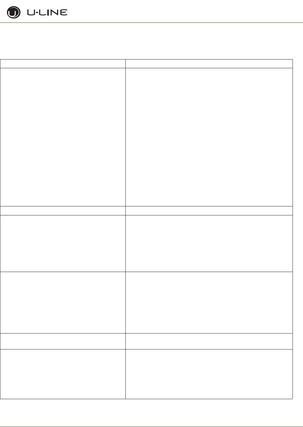
CUSTOMER CALL GUIDE
The following guide has been developed to help answer
frequently asked questions. It can be used by persons scheduling service calls. Things to consider before
scheduling a service call:
Concern Response
The unit is not cold enough. • Are you familiar with the factory temperature specifications for
your unit? Many factors can cause these temperatures to vary;
ambient temperature, application, amount of use (number of times
and length of time the door or drawers or opened and closed),
etc.
• Is the door or drawers sealing properly? If the door or drawer is
not sealed properly, it allows heat into the unit. U-Line’s warranty
is 90 days for door or drawer adjustments.
• Has the door or drawers been left open?
• Is the condenser clean? U-Line’s warranty does not cover cleaning
the condenser.
• Is the unit behind closed doors or the vent restricted? The front
grille must be free of obstruction.
• Is the unit in an application of heavy usage? Heavy usage or high
ambient temperatures will cause a unit to frost up.
• Did you try adjusting the temperature to a colder level? Adjust to
a colder level. Be sure to allow 24 hours between temperature
control adjustments.
Temperature is too cold. Check actual temperature versus set-point.
The unit is frosting up. • Are you familiar with the defrost technology of your unit?
• Is the door or drawers sealing properly? If the door or drawer
is not sealing properly, it allows heat/humidity into the unit.
U-Line’s warranty is 90 days for door or drawer adjustments.
• Has the door or drawers been left open?
• Is the unit in an application of heavy usage? Heavy usage or high
ambient temperatures will cause a unit to frost up.
The ice cubes are sticking together. • Is the door or drawers sealing properly? This could cause the ice
cubes to stick together.
• Have you tried to shake the ice bucket? If the ice sits without
being used, it will tend to stick together. Shaking the bucket will
usually break the ice cubes apart. If the ice has been sitting for a
long time, you should consider discarding it and make a fresh
batch.
• Does the unit need to be defrosted?
Water is leaking out of the unit. Have you checked the water connection to the unit? U-Line’s
warranty does not cover installation adjustments.
No ice or not enough ice. • Are you aware of the factory specifications for ice production?
• Is the ice maker bin arm down? When the arm is up, the ice
maker will not make ice.
• Is the door or drawers sealing properly? U-Line’s warranty is 90
days for door adjustments.
• Has the ice maker been turned off at the display?
2-2
Section 2 - Troubleshooting
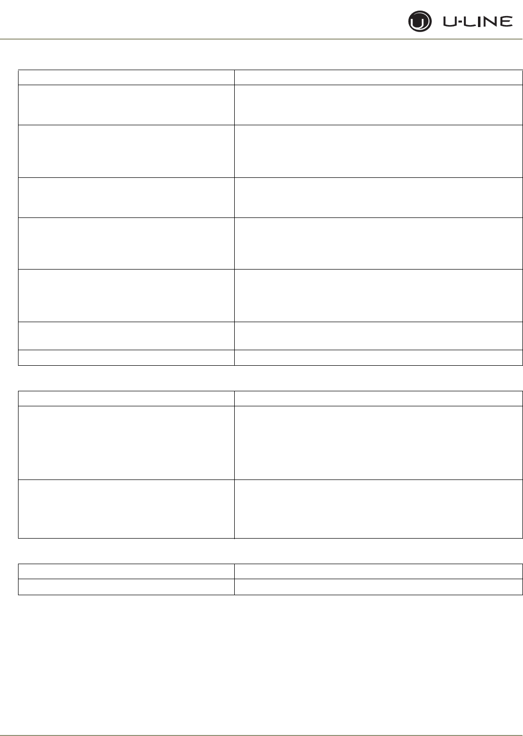
CLR2160 Model Only:
Drawer Models Only:
2175DWRR Model Only:
Concern Response
The cubes are wet. • The storage bin that holds the ice is not refrigerated. The
cubes in the bin are slowly melting down. The bin will
maintain a temperature of 32°F to 34°F.
The floor is very warm in front of my unit. • The unit is designed for a built-in application, so warm air
will vent through the front grille, below the door. There
is a safety feature built into the control board that will
shut down the unit if warm air can’t vent or is restricted.
No ice, but water pours into the trough and
down into the drain.
• The standpipe needs to be inserted into the drain hole of
the water trough to maintain the proper level of water
inside the trough.
When the unit is turned on, all I get is water
fill.
• Once the unit is turned on, there will be a three-minute
water fill. This ensures a fresh batch of water has filled
the trough. If water flows more than three minutes, a
service call will be required.
The ice does not come out in a perfect cube
shape.
• When the ice is made, a small hole or “dimple” will
appear on the front or top of the cube. Increasing or
decreasing the time of the freeze cycle will adjust the size
of the dimple.
The cubes do not fall into the bin as
individual cubes.
• This is normal. You can use the scoop to break the cubes
apart.
Not enough ice is stored in the bin. • Make sure unit is level.
Concern Response
There is excessive condensation on the mullion. • The mullion has a heater behind it that should keep the mullion free of
frost and sweat. In extremely humid conditions, some sweat may appear
on the mullion or lower drawer handle/gasket. The heater will not
operate in ambient temperatures over 90°F.
• Drawer units should not be used outdoors or in an area that is not air-
conditioned.
Drawer will not close properly. • The drawer slides have a self-closing feature which engages when the
drawer is about 1” (25.4mm) from being closed. There may be some
resistance. If the resistance is hard to overcome, try closing the drawers
with more force a couple of times and then try slowly closing the drawers
again.
Concern Response
There is a water leak inside the unit. • Make sure the drain is not blocked. Remove any blockage.
2-3
Section 2 - Troubleshooting
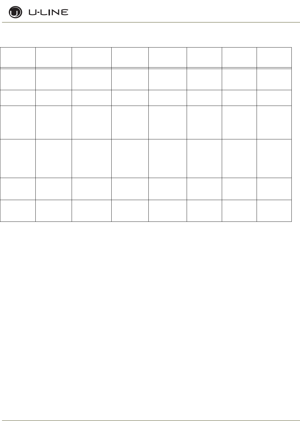
REFRIGERATION SYSTEM DIAGNOSIS GUIDE
THERMISTOR TYPES
Type 1 (Black)
Resistance at 77°F = 10,000 Ohms ± 5%.
Operating range is 185,000 to 650 Ohms. Resistance goes
down as temperature increases. Type 1 does not need to be
calibrated and can be changed without changing other wires
or board.
Type 2 (White)
Resistance at 77°F = 5,000 Ohms ± 5%.
Operating range is 180,000 to 550 Ohms. Resistance goes
down as temperature increases. Type 2 does not need to be
calibrated and can be changed without changing other wires
or board.
System
Condition
Suction
Pressure
Suction
Line
Compressor
Discharge
Condenser Capillary
Tube
Evaporator Wattage
Normal Normal Slightly below
room
temperature
Very hot Very hot Warm Cold Normal
Overcharge Higher than
normal
Very cold may
frost heavily
Slightly warm
to hot
Hot to warm Cool Cold Higher than
normal
Undercharge Lower than
normal
Warm-near
room
temperature
Hot Warm Warm Extremely
cold near
inlet - Outlet
below room
temperature
Lower than
normal
Partial
Restriction
Somewhat
lower than
normal
vacuum
Warm - near
room
temperature
Very hot Top passes
warm - Lower
passes cool
(near room
temperature)
due to liquid
Room
temperature
(cool) or
colder
Extremely
cold near
inlet - Outlet
below room
temperature
backing up
Lower than
normal
Complete
Restriction
In deep
vacuum
Room
temperature
(cool)
Room
temperature
(cool)
Room
temperature
(cool)
Room
temperature
(cool)
No
refrigeration
Lower than
normal
No Gas 0 PSIG to 25” Room
temperature
(cool)
Cool to hot Room
temperature
(cool)
Room
temperature
(cool)
No
refrigeration
Lower than
normal
2-4
Section 2 - Troubleshooting
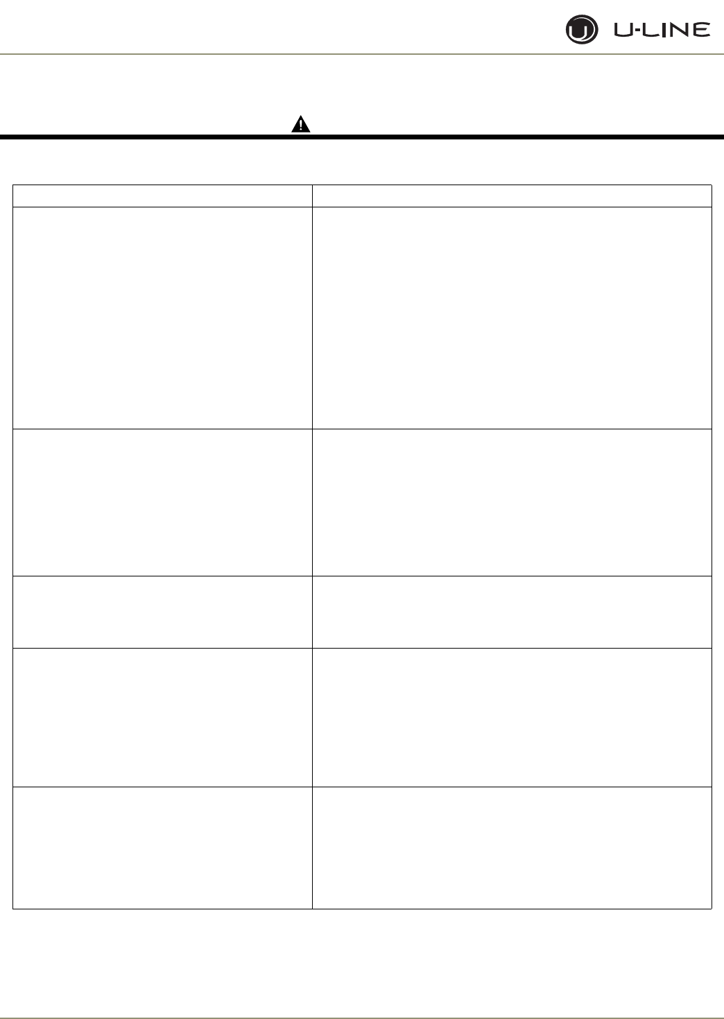
TROUBLESHOOTING
DANGER
Never attempt to repair or perform maintenance on the unit until the main electrical power has been
disconnected from the unit.
Cause Remedy
Will not eject ice (water frozen).
1. Control setting too cold.
2. Control inoperable.
3. Bin switch inoperable.
4. Limit switch defective (open).
5. Ice maker assembly motor stalled.
6. Broken wire in ice maker circuit.
7. Water soaked cabinet insulation.
8. Dirty condenser.
1. Adjust control warmer.
2. Replace control.
3. Replace bin switch.
4. Replace limit switch.
5. Replace motor.
6. Repair or replace wiring.
7. Replace foamed cabinet assembly.
8. Clean condenser.
Will not fill with water.
1. Water supply valve closed.
2. Water switch inoperable (open).
3. Solenoid valve inoperable.
4. Fill tube outlet frozen.
5. Broken wire in water fill circuit.
1. Open water supply valve.
2. Replace water switch.
3. Replace solenoid valve.
4. Defrost fill tube.
5. Repair or replace wiring.
Will not stop making ice.
1. Bin switch inoperable (closed).
2. Bin arm binding.
1. Replace bin switch.
2. Lubricate bin arm pivot points or loosen bin arm lever screw.
Water will not stop filling.
1. Water switch inoperable (closed).
2. Solenoid valve inoperable.
3. Stalled ice maker motor.
4. Temperature control inoperable. Ice maker is in
continuous harvest cycle.
1. Replace water switch.
2. Replace solenoid valve.
3. Replace motor.
4. Replace temperature control.
Ejector blades will not stop turning.
1. Control inoperable.
2. Hold switch inoperable.
3. Broken wiring.
4. Short in mold heater.
1. Replace control. Replace hold switch.
2. Repair or replace wiring.
3. Replace heater.
4. Replace mold heater.
2-5
Section 2 - Troubleshooting
Low ice production.
1. Control set too cold.
2. Fan motor stalled.
3. Ice cubes too large.
4. Dirty condenser.
5. Bypass valve stuck open (Frost Free units only).
1. Adjust control warmer.
2. Replace fan motor.
3. Lower water fill adjustment.
4. Clean condenser.
5. Replace bypass valve (Frost Free units only).
Not freezing (compressor and fan motors
operating).
1. Little or no frost pattern on evaporator.
2. Bypass valve stuck open (Frost Free units only).
1. Check for sealed system leak or restriction.
2. Replace bypass valve (Frost Free units only).
Not freezing (compressor not operating - fans
operating).
1. Relay inoperable.
2. Overload inoperable (open).
3. Compressor inoperable.
1. Replace relay.
2. Replace overload.
3. Replace compressor.
Not freezing (compressor and fans not operating).
1. Power cord not plugged in.
2. Unit turned off.
3. Control panel inoperable.
4. Hold switch inoperable (open).
5. Control inoperable.
6. Broken wire in freeze circuit.
7. Ejector blades not in freeze position (12:00)
1. Plug in power cord.
2. Press On/Off button to turn unit on.
3. Replace control panel.
4. Replace hold switch.
5. Replace control.
6. Repair or replace wiring.
7. Manually advance ejector blades to the 12:00 position (test ice
maker and limit switch).
Compressor overheating.
1. Condenser air flow restricted.
2. Condenser fan blade obstructed.
3. Condenser fan motor stalled.
4. Compressor inoperable.
1. Remove restriction (clean condenser and grille).
2. Remove blade restriction.
3. Replace fan motor.
4. Replace compressor.
Compressor will not stop operating.
1. Temperature set too cold.
2. Control inoperable.
3. Control sensing bulb not sensing mold
temperature.
4. Evaporator fan stalled.
1. Adjust temperature warmer.
2. Replace control.
3. Fully insert bulb into ice maker tube. Rout bulb away from
compressor discharge tube.
4. Remove obstruction or replace motor.
Cause Remedy
2-6
Section 2 - Troubleshooting
Water leak (under unit).
1. Water supply line leaking at solenoid valve inlet.
2. Water line leaking at solenoid valve outlet.
3. Water line leaking at fill tube.
4. Defrost drain line not in drain pan.
5. Crack in water line.
1. Tighten or replace fitting.
2. Replace water line and fitting.
3. Tighten clamp or replace fill tube assembly.
4. Position drain line in drain pan.
5. Replace water line.
Water leak (inside unit).
1. Ice maker assembly fill cup obstructed.
2. Fill ice cup and fill tube out of alignment.
3. Water level too high.
4. Defrost drain plugged (Frost Free units only).
1. Remove obstruction.
2. Align fill tube and fill cup.
3. Adjust water level.
4. Ice in drain trough (Frost Free units only) (see below).
Excessive frost buildup.
1. Door gasket not sealing properly.
2. Door out of alignment.
3. Water soaked cabinet insulation.
4. Light stays on when door is closed.
1. Adjust door hinges or replace door gasket.
2. Adjust door hinges.
3. Replace foamed cabinet assembly.
4. Repair or adjust light bracket.
Noisy.
1. Copper refrigeration tube touching cabinet.
2. Fan blade touching shroud.
3. Fan blade obstruction (wiring, foam insulation,
packaging material).
1. Carefully adjust tubing.
2. Adjust fan mounting or shroud.
3. Remove obstruction.
Ice buildup in drain trough or drainage problem.
1. Obstructed drain cup or tube.
2. Drain trough heater failed (Frost Free units
only).
3. Kinked drain tube.
4. Drain trough spout and drain cup not aligned.
1. Clear obstruction.
2. Replace drain trough heater (Frost Free units only).
3. Reroute drain tube.
4. Align drain trough and drain cup.
Unit will not defrost (Frost Free units only).
1. Bypass coil inoperable.
2. Defrost timer inoperable.
3. Bypass valve inoperable.
1. Replace bypass valve.
2. Replace defrost timer.
3. Replace bypass valve.
Fresh food temperature too cold.
1. Temperature control set too cold.
2. Bin/Freezer door not closing.
3. Ice bucket not fully inserted.
1. Adjust control to warmer setting (counterclockwise).
2. Adjust or replace door.
3. Check for ice behind bucket and push ice bucket in place.
Cause Remedy

3-1
Section 3 - Service and Repair
OPERATION
CLR2160
GENERAL
Upon initial startup, this unit will enter mode number 5
which is a three-minute water fill regardless of the
thermistor temperatures. This only occurs when the initial
startup is caused by a power-up of the main board.
Following the three-minute water fill, the unit moves into mode 1
which is the freezing mode. In this mode the water is pumped from
the sump trough over the ice maker grid by the circulation pump.
This mode typically lasts 10-20 minutes and is regulated by the
temperature of the thermistor mounted near the dryer
(thermistor 4).
At the conclusion of the freeze cycle the unit will enter mode 2
which is the ice harvest. This harvest can last up to three minutes.
During this mode the water trough also refills.
Before the next cycle begins, the custom electronic board
determines whether the bin is full. A temperature below 34°F, or a
temperature below 35°F for at least one hour will stop the unit
from producing ice. The ice-making will always stop at the
conclusion of a harvest cycle. It will never stop in the middle of a
cycle.
The custom electronic board continuously monitors the optional
P60 pump to ensure the drain line is not becoming restricted. In
the event of a drain line obstruction, the display interface will show
“P1.” If the drain remains restricted the unit will stop ice
production until the drain clears. In the event of a partially
restricted drain, reduced ice rate will be noticed as the unit
continuously turns on and off to eliminate any chances of overfilling
the unit with water. If no pump is used the pink jumper needs to be
connected to the power cord in its place.
A cleaning mode is available through the user interface by using the
key sequence described in the Controls Section. The cleaning
mode lasts about 45 minutes, at which point the unit will sit idle
for another 15 minutes. During this time the display will show
“CL.” At the conclusion of the cycle the unit will automatically turn
back on.
THERMISTOR OUTAGE
In the event that a thermistor fails, the unit will stop all functions
and display “ER” on the user interface. The exact error can be
accessed via the service mode.
SERVICE
The CLR2160 model uses four relays and two thermistors. There
is a variety of built-in servicing features to aid in diagnosing the
root problem associated with a unit.
To check to see which relays are currently operating, hold the
COLDER key and press the ON/OFF key three times. When
entering the sequence, keep the COLDER key pressed until you
completely release the ON/OFF key for the third time. The display
will cycle through a series of numbers to tell which relays are
energized. For example, if the unit was in ice-making mode the
display would show 11 20 31 40 51 60 70. The first number is the
relay number. In the second number, “1” means on and “0” means
off. The relay information can be found in the Control Section.
Each relay can also be turned on and off individually to determine
whether or not the board and component are operating. If a board
is suspected of not operating correctly you can run through this
sequence to ensure each component is turning on and off through
the board correctly. Go into service mode and choose option #22.
This will cycle every relay on and off showing 10 11 20 21 …. If a
component fails to turn on when the relay does, you can verify if
there is voltage present by using a voltmeter to check the board
output.
To view the actual thermistor readings, hold the WARMER and
COLDER keys for about five seconds. The display will cycle
through the three thermistors and their temperatures. If a
thermistor is unused in a unit it will show a “0” reading. The
CLR2160 uses thermistors 2 and 4. For thermistor 4 the display
will only show up to “99.” In the event the temperature is higher
than this the display will show a flashing “99.”
TROUBLESHOOTING
Error Codes
E1, E2, E9 Bad thermistor errors. Replace thermistor. Check
for thermistor errors by accessing “View thermistor
# status (2,19, 20, or 21).” If the error code is
repeated, the thermistor is open or shorted. If a
temperature is displayed, the thermistor is not
defective.
P1 Pump circuit is detecting a drain problem. Consult a
plumber to resolve the issue. If unit does not have a
P60 installed, then the jumper wire is missing in
place of the pump.
Any other error messages will not affect the operation of the
CLR2160 model.
After checking the errors be sure to clear the error log by
performing service option 12
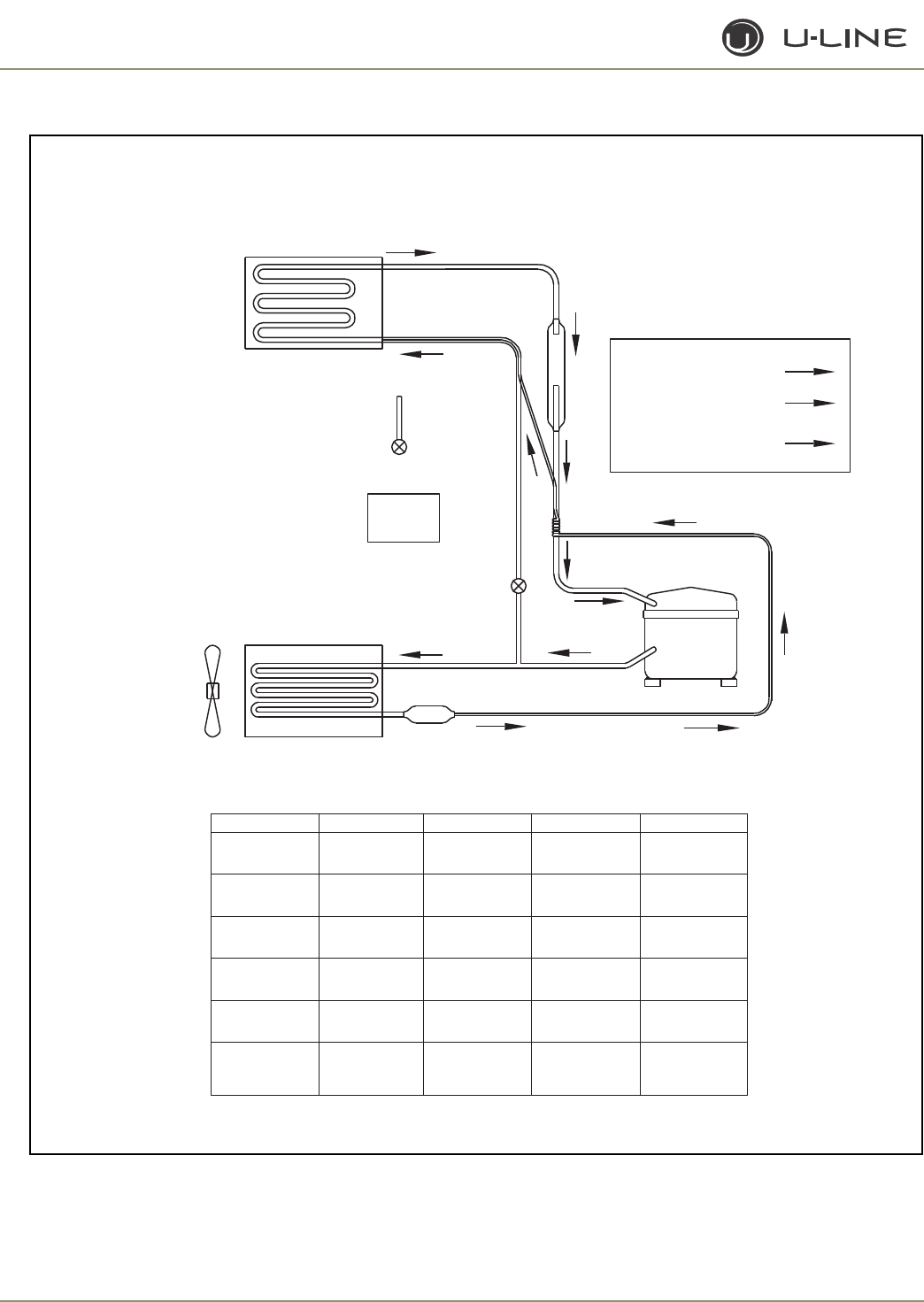
3-2
Section 3 - Service and Repair
.
Figure 1. CLR2160
HIGH PRESSURE
LOWPRESSURE
TRANSITIONAL PRESSURE
IN CAPILLARY TUBE
H
L
C
L
L
C
C
C
C
C
L
L
H
H
C
L
ICEMAKER EVAPORATOR
2276
R4: WATER
SUPPLY
R5: WATER
CIRCULATION PUMP
R4: HOT GAS
BYPASS
VALVE
R1: CONDENSER
FAN
CONDENSER
R3: COMPRESSOR
RELAY R1 R3 R4 R5
FUNCTION FAN
ON
ON
OFF
OFF
OFF
ON
ON
OFF
OFF
OFF
OFF
ON
OFF
ON/OFF
ON*
ON
OFF
OFF
ON/OFF
OFF
COMP CIRC PUMP
HOT GAS /
WATER IN
Mode 1:
Ice Making
Mode 2:
Ice Harvest
Mode 3:
Off
Mode 4:
Cleaning
Mode 5:
Water Fill &
Initial Start-Up
* Normal Start-Up lasts 3 minutes
Note: R2, R6 and R7 not used

3-3
Section 3 - Service and Repair
TROUBLESHOOTING (CONTINUED)
No ice
Check the ice bin temperature. If the temperature is in the 34-
35°F range, the unit is shut down due to low temperature inside.
This could be caused by low ambient temperatures or running the
unit without a water supply attached.
If the ice bin temperature is above 35°F, the unit should be
producing ice. Check to ensure the water trough is full and the
pump is operating.
Too much ice
Ensure there is Permagum around the thermistor hole. If there is,
proceed to the next step.
The control board is equipped with an adjustment to adjust the
level of ice in the bin for customer preference or when used in
abnormal installations. With ice stacked to the desired level, check
the bin temperature by holding WARMER and COLDER for five
seconds. We’ll assume the display showed 38°F for this example.
Go to service mode #24 and adjust the setting to that number.
This will allow the bin to shut off at this ice level. This temperature
needs to be checked after the door has been closed for at least 10
minutes in order for the thermistor temperature to stabilize.
Too little ice
If this is a recurring issue, try adjusting service option #24 colder in
1 or 2° increments until the desired level of ice is achieved.
Ice not sized to customer satisfaction
The thickness of the cubes can be adjusted per the ice thickness
section of the manual.
Noise
Some noise from this unit is normal. You may hear the sound of ice
dropping into the bin, especially when it is empty. The harvesting
processes involves flowing refrigerant and water through valves
which may produce a rushing type sound during the harvest. The
fan and compressor will produce a continuous low motor noise. If
installed, the P60 pump will produce noise at regular intervals as it
empties water from the unit. If any of these is objectionable, the
unit has an Office mode which can be entered for three hours at a
time. During this mode the unit will not produce ice; however, the
drain pump will continue to operate.
No water in trough
Ensure the standpipe is fully inserted into the trough.
Check the water valve to see if it is filling the unit.
Watch the water flow over the mold to see if excess water is being
splashed out of the trough. This could be the result of improper
leveling.
Ice does not release from evaporator
This could be caused by improper leveling or the unit is in need of
cleaning.
Poor ice quality
This can be caused by poor incoming water quality. The CLR2160
is designed to produce clear ice in most water; however, abnormal
water conditions may result in the need for further filtering.
Water in ice bin
A defect in the drain from the unit will cause water to stop
draining from the unit.
Display is showing something other than “Ice,” “ER”
or “CL.”
Push one of the keys to see if the display is reset.
Turn unit on and off via the display pad.
Unplug unit, wait one minute and plug back in. If any of these steps
return the unit to operation the unit was probably accidently
entered into a service mode.
Display is showing a random snaking of characters
or a degree symbol is flashing.
The unit is in a special showroom mode. Hold the COLDER key
and press the LIGHT key three times to exit.
Display not illuminating but unit operating
First try to plug and unplug the unit. If the display still does not
illuminate, there is a four-wire pin connector running from the
main board in the base to the display board. One of the wires is
disconnected or damaged.
Unit is not operating—no cooling—no fans.
Unplug unit and plug back in. If main board beeps when plugging in
the unit then this is most likely a system problem not a board issue.
If board does not beep when plugging in the unit, check the power
supply to ensure the outlet is working. Also, check the fuse on the
circuit board.

3-4
Section 3 - Service and Repair
CLRCO2175
GENERAL
The U-Line Model CLRCO2175 combines the best of Échelon
refrigeration and clear ice-making capabilities into a single unit. A
state-of-the-art microprocessor-based controller simplifies
operation and troubleshooting. There are four primary modes of
operation:
1. Ice Making and Refrigeration (Figure 2).
2. Ice Making and No Refrigeration (
Figure 3)
.
3. Refrigeration and No Ice Making (
Figure 4
).
4. Ice Harvest/Water fill (No Refrigeration Possible)
(
Figure 5
).
In addition, there are three sub modes of operation:
5. Off (
Figure 6
).
6. Water Fill - No Refrigeration (
Figure 7
).
7. Cleaning (No Refrigeration Possible) (
Figure 8
).
Review the following notes for general information before reading
the schematics.
These are some additional general notes and exceptions:
• The controller has a four-minute compressor minimum off-
cycle regardless of thermistor status, for compressor
protection and cycling.
• When making ice, the controller reads liquid line temperature
four minutes into the ice-making cycle to determine the length
of that ice-making cycle and subsequent harvest length.
• Once an ice-making cycle is initiated, it will continue through to
harvest regardless of the bin sensor.
• There is a three-minute water fill cycle when the unit is turned
on. Mode 6.
• In order to maintain adequate refrigerator temperature, the
unit will sometimes run in the refrigeration only mode, as
shown in Mode 3, even if the ice bin sensor is calling for ice. At
the end of each ice harvest, the controller checks the
refrigerator sensor and if it is warmer than the higher of 42°F,
or the set-point, it will go into refrigeration only mode. The
refrigerator must be at 42° or setpoint to make ice
continuously. Example:
Setpoint Temperature
38° 42° or lower ice
38° 45° no ice
55° 55° ice
55° 58° no ice
There is no fill cycle when ice-making re-initiates in this case
because the bin sensor has not been satisfied.
• When the initial three-minute fill cycle is complete, the unit will
enter ice making and refrigeration mode (1) if the bin is empty
or below the sensor. However, after the first slab of cubes is
harvested, the controller will follow the logic defined in 5 above
and realizing the refrigerator is too warm, will continue in
refrigeration only mode (3) until the requirement is satisfied.
Thus, upon start-up, the user will see one slab of ice dropped in
about 30 minutes, and then there will be no more ice until the
refrigerator reaches 42°F or set-point. (This may be two to
three hours depending on ambient conditions.)
• There will also be a water fill cycle after the ice bin has been
“full” and then calls to make ice again. This can occur when the
refrigerator side is off as shown in Mode 6, or when it is on,
which is shown in Mode 8. If the refrigerator side is on, when
the fill cycle initiates, it will remain on until the fill cycle is
completed, even if the refrigerator sensor is satisfied.
• The controller has a four-degree differential designed into it for
the refrigerator sensor, such that when it is set to 38°F, the
refrigerator will cool until the refrigerator sensor reads 36°F
and will not re-initiate refrigerator cooling until the sensor
reaches 40°F. So someone monitoring actual temperature (by
pressing WARMER momentarily) may see the refrigerator off
when the temperature is a degree warmer than set-point, or
refrigerator on when it is a degree below set-point. Refer to
Echelon Keypad.
• There is no high limit cut-out on this unit; however, if the liquid
line sensor were to go out of range (approximately 185°F) the
ice maker side of the unit will shut down. The refrigerator will
continue to run. When the temperature of the liquid falls back
in range, the unit will re-initiate operation. The unit will not
normally experience this condition up to 110°F, but conditions
such as door openings, heavy loading, restricted airflow, dirty
condenser or direct sunlight may contribute to reaching this
mode.
• Different from the earlier CLRCO2075, this unit uses two
relays to control the refrigeration valves. This means that the
valves will only be energized when needed.
• There is now a thermistor on the refrigerator evaporator that
will sense the evaporator plate temperature. This will allow the
unit to fully defrost based on temperature of the evaporator
plate during the defrost modes.
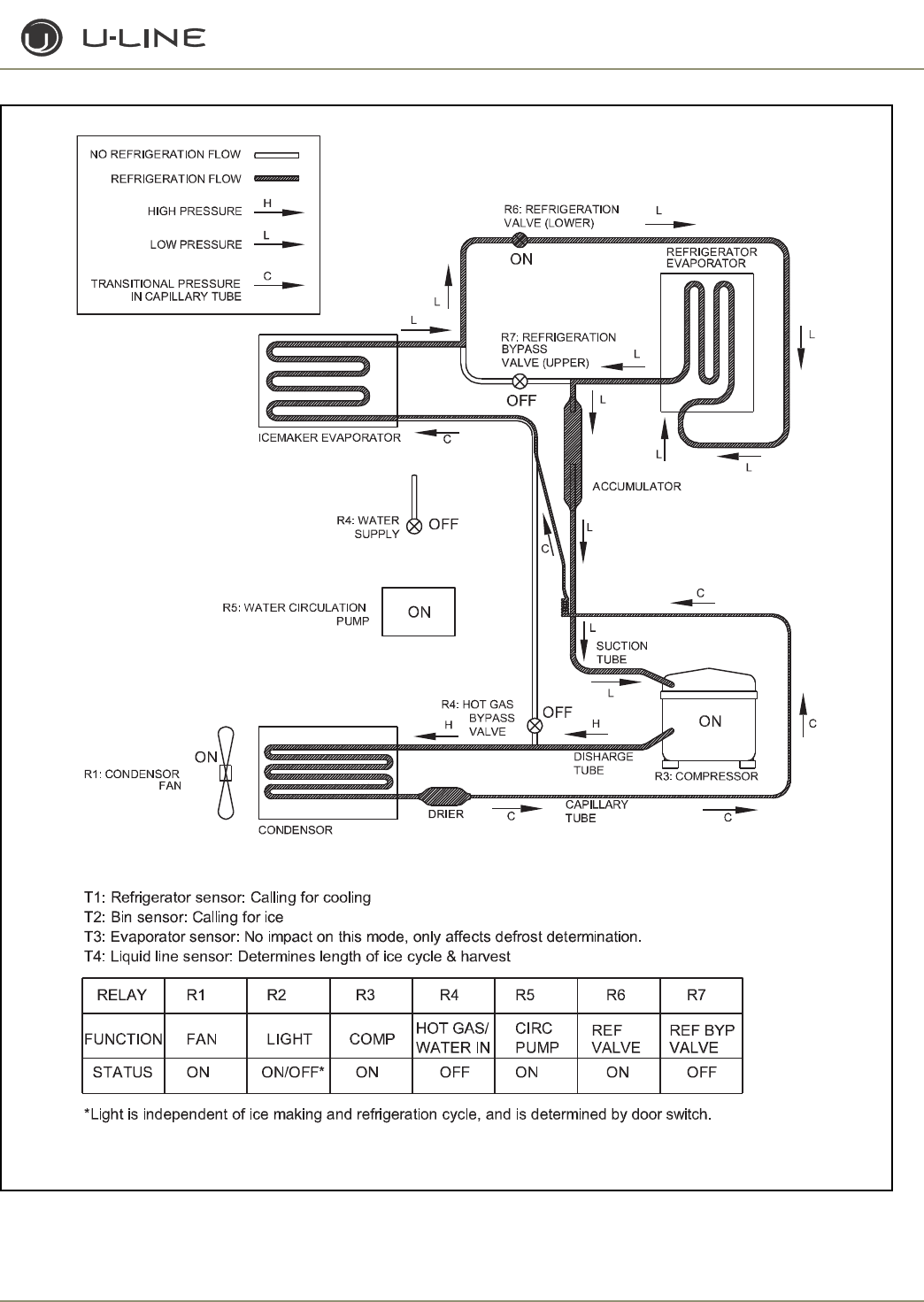
3-5
Section 3 - Service and Repair
Figure 2. CLRCO2175 Mode 1: Ice Making and Refrigeration
ULIN_0328_A
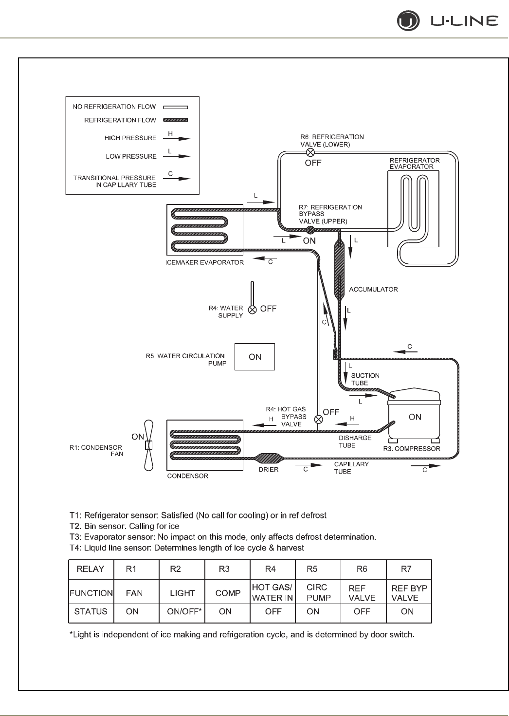
3-6
Section 3 - Service and Repair
Figure 3. CLRCO2175 Mode 2: Ice Making and No Refrigeration (or Ref Defrost)
ULIN_0329_A
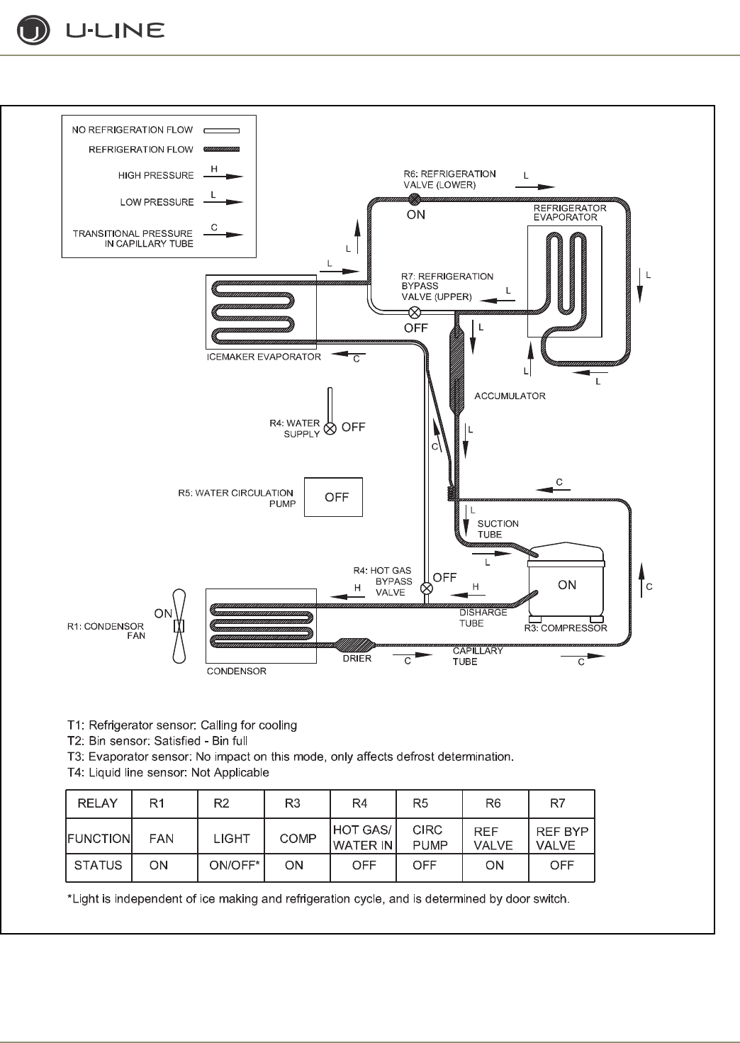
3-7
Section 3 - Service and Repair
Figure 4. CLRCO2175 Mode 3: Refrigeration and No Ice Making
ULIN_0330_A
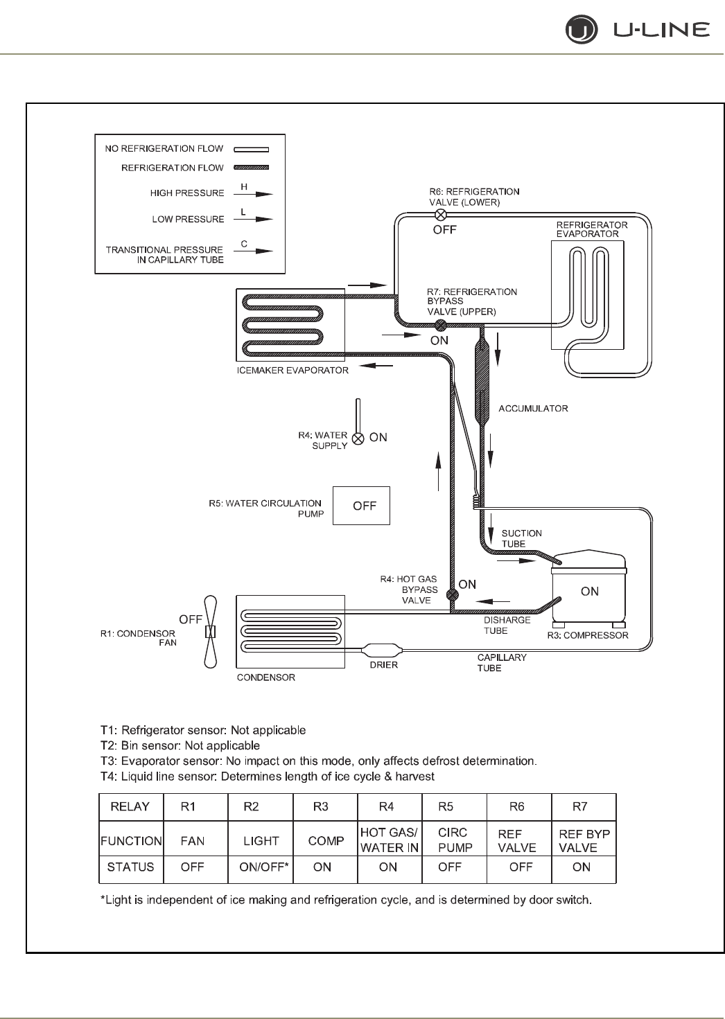
3-8
Section 3 - Service and Repair
Figure 5. CLRCO2175 Mode 4: Ice harvest (No Refrigeration Possible)
ULIN_0331_A
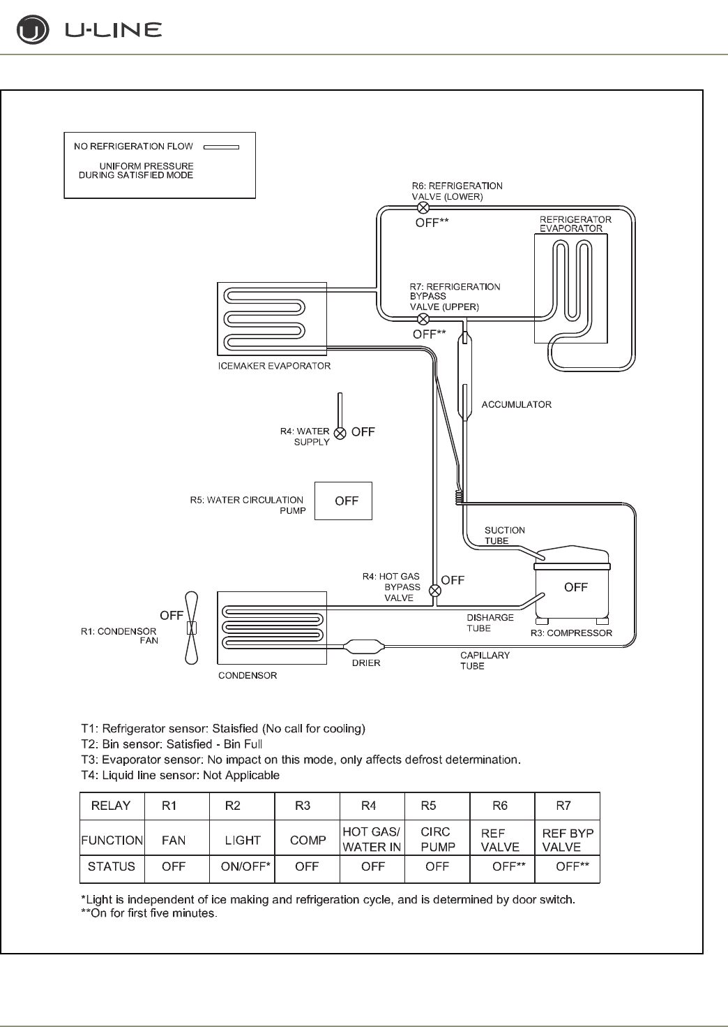
3-9
Section 3 - Service and Repair
Figure 6. CLRCO2175 Mode 5: Off
ULIN_0332_A
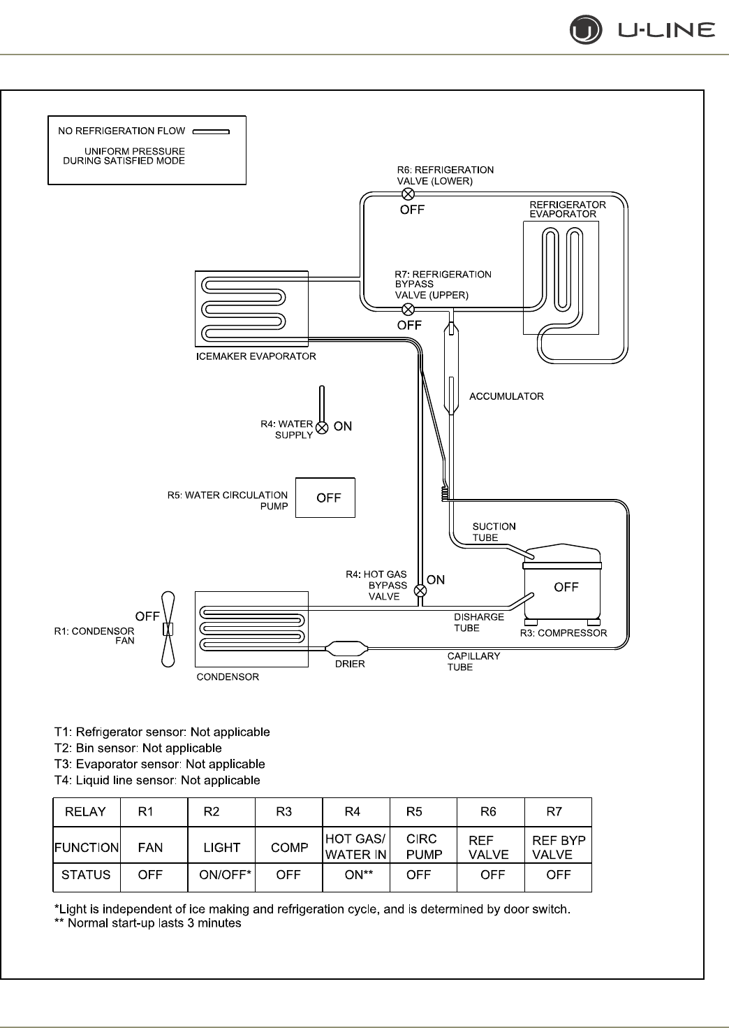
3-10
Section 3 - Service and Repair
Figure 7. CLRCO2175 Mode 6: Water Fill - No Refrigeration Possible (Normal Start-Up)
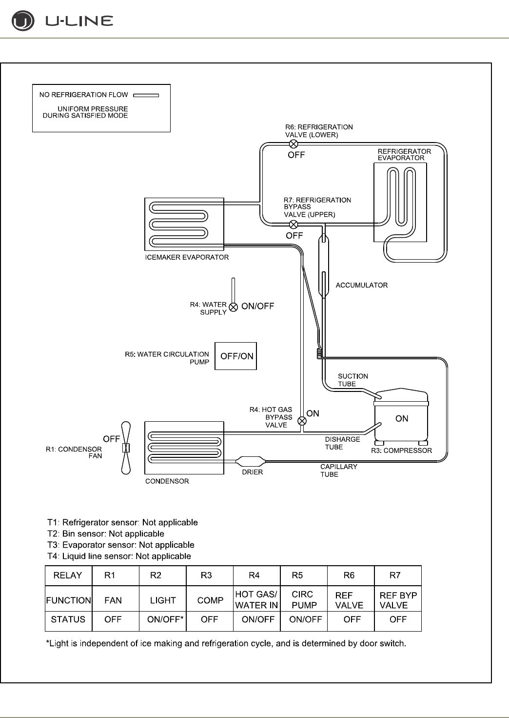
3-11
Section 3 - Service and Repair
Figure 8. CLRCO2175 Mode 7: Cleaning (No Refrigeration Possible)

3-12
Section 3 - Service and Repair
THERMISTOR OUTAGE
In the event that the condenser thermistor (T4) fails, the unit will
stop all functions and display “ER” on the user interface. The exact
error can be accessed via the service mode.
If the refrigerator thermistor (T1) fails, the refrigerator will stop
operation; however, the ice maker will continue to function. The
display will show “ER.” The exact error can be accessed via the
service mode.
If the ice bin thermistor (T2) fails, the ice maker will stop functioning;
however, the refrigerator will continue to work. The display will
show “ER.” The exact error can be accessed via the service mode.
If the refrigerator evaporator thermistor (T3) fails, the unit will
function normally; however, defrosting will occur on a timing interval
instead of timing and temperature. The display will show “ER.” The
exact error can be accessed via the service mode.
SERVICE
The CLRCO2175 model uses seven relays and four thermistors.
There is a variety of built-in servicing features to aid in diagnosing the
root problem associated with a unit.
To check to see which relays are currently operating, hold the
COLDER key and press the ON/OFF key three times. When entering
the sequence keep the COLDER key pressed until you completely
release the ON/OFF key for the third time. The display will cycle
through a series of numbers to tell which relays are energized. For
example, if the unit was in ice-making mode, the display would show
11 20 31 40 51 60 70. The first number is the relay number. In the
second number, 1 means ON and 0 means OFF. The relay
information can be found in the Control Section.
Each relay can also be turned on and off individually to determine
whether or not the board and component are operating. If a board is
suspected of not operating correctly, you can run through this
sequence to ensure each component is turning on and off through
the board correctly. Go into service mode and choose option #22.
This will cycle every relay on and off showing 10 11 20 21 …. If a
component fails to turn on when the relay does, you can verify if
there is voltage present by using a voltmeter to check the board
output.
To view the actual refrigerator (T1) temperature, hold the WARMER
key until the actual temperature is displayed. To view the actual
thermistor readings for 2-4, hold the WARMER and COLDER keys
for about five seconds. The display will cycle through the three
thermistors and their temperatures. If a thermistor is unused in a unit
it will show a “0” reading. For thermistor 4 the display will only show
up to “99.” In the event the temperature is higher than this, the
display will show a flashing “99.”
In the general section the methods to enter some other service
modes are available. For the CLRCO2175 model some useful modes
are the ICE MAKER OFF MODE, FORCED REFRIGERATOR
DEFROST, ICE THICKNESS ADJUST, CLEAN, AND TEMPORARY
SHUTDOWN MODE. These can be useful in servicing the unit.
TROUBLESHOOTING:
Error Codes
E1, E2, E7, E8, E9 Bad thermistor errors. Replace thermistor.
Check for thermistor errors by accessing
“View thermistor # status (2, 19, 20, or 21).” If
the error code is repeated, the thermistor is
open or shorted. If a temperature is displayed,
the thermistor is not defective.
E3 This will be accompanied by a beep every
minute. This signals that the door has been left
open for longer than 20 minutes. Close the
door to reset. If the light and display do not go
off when the door is closed, check to make
sure the magnet is positioned properly.
E5 This signals that the unit has been above set-
point for more than twelve hours by at least
10°. If the unit was just plugged in leave for 24
hours to see if the problem is corrected. If it is
not corrected, it is most likely a refrigeration
system issue.
E6 This signals that the refrigerator section has
been at least 10° below set-point for at least
twelve hours. This would most likely be caused
by a bad relay and the circuit board.
P1 Pump circuit is detecting a drain problem.
Consult a plumber to resolve the issue. If unit
does not have a P60 installed, then the jumper
wire is missing in place of the pump.
After checking the errors, be sure to clear the error log by
performing service option 12.
No ice
Check the ice bin temperature. If temperature is in the 34-35°F range
the unit is shut down due to low temperature inside. This could be
caused by low ambient temperatures or running the unit without a
water supply attached.
If the ice bin temperature is above 35°F the unit should be producing
ice. Check to ensure the water trough is full and the pump is
operating. If the components are not operating, see the service
section above.

3-13
Section 3 - Service and Repair
Too much ice
Ensure there is Permagum around the thermistor hole. If there is,
proceed to the next step.
The control board is equipped with adjustment to adjust the level
of ice in the bin for customer preference or when used in
abnormal installations. With ice stacked to the desired level, check
the bin temperature by holding WARMER and COLDER for five
seconds. We’ll assume the display showed 38°F for this example.
Go to service mode #24 and adjust the setting to that number.
This will allow the bin to shut off at this ice level. This temperature
needs to be checked after the door has been closed for at least 10
minutes in order for the thermistor temperature to stabilize.
Too little ice
If this is a recurring issue, try adjusting service option #24 cooler
in 1 or 2° increments until the desired level of ice is achieved.
Ice not sized to customer satisfaction
The thickness of the cubes can be adjusted per the ice thickness
section of the manual.
Noise
Some noise from this unit is normal. You may hear the sound of ice
dropping into the bin, especially when it is empty. The harvesting
process involves flowing refrigerant and water through valves
which may produce a rushing type sound during the harvest. The
fan and compressor will produce a continuous low motor noise. If
equipped, the P60 pump will produce noise at regular intervals as it
empties water from the unit. If any of these is objectionable the
unit has an Office mode which can be entered for three hours at a
time. During this mode the unit will not produce ice; however, the
drain pump will continue to operate.
No water in trough
Ensure the stand pipe is fully inserted into the trough.
Check the water valve to see if it is filling the unit.
Watch the water flow over the mold to see if excess water is being
splashed out of the trough. This could be the result of improper
leveling.
Ice does not release from evaporator
This could be caused by improper leveling or the unit is in need of
cleaning.
Poor ice quality
This can be caused by poor incoming water quality. The
CLRCO2175 is designed to produce clear ice in most water;
however, abnormal water conditions may result in the need for
further filtering.
Water in ice bin
A defect in the drain from the unit will cause water to stop
draining from the unit.
Display is showing something other than “SP (38),”
“ER” or “CL.”
Push one of the keys to see if the display is reset.
Turn unit on and off via the display pad.
Unplug unit, wait one minute and plug back in. If any of these steps
returns the unit to operation the unit was probably accidently
entered into a service mode.
Display is showing a random snaking of characters
or a degree symbol is flashing.
The unit is in a special showroom mode. Hold the COLDER key
and press LIGHT three times to exit.
Display not illuminating but unit operating
First try to plug and unplug the unit. If the display still does not
illuminate there is a four-wire pin connector running from the main
board in the base to the display board. One of the wires is
disconnected or damaged.
Unit is not operating—no cooling—no fans.
Unplug unit and plug back in. If main board beeps when plugging in
the unit then this is most likely a system problem, not a board
issue.
If board does not beep when plugging in the unit, check the power
supply to ensure the outlet is working. Also, check the fuse on the
circuit board.
Refrigerator not cooling but ice maker working
Check to ensure the refrigerator thermistor is working properly.
Ice maker not operating—no water flowing over
mold
The refrigerator needs to be at or below set-point (or 42°F) to
start the ice-making process. If the unit is cool enough there could
be a defective bin thermistor, defective condenser thermistor or
defective solenoid coil.
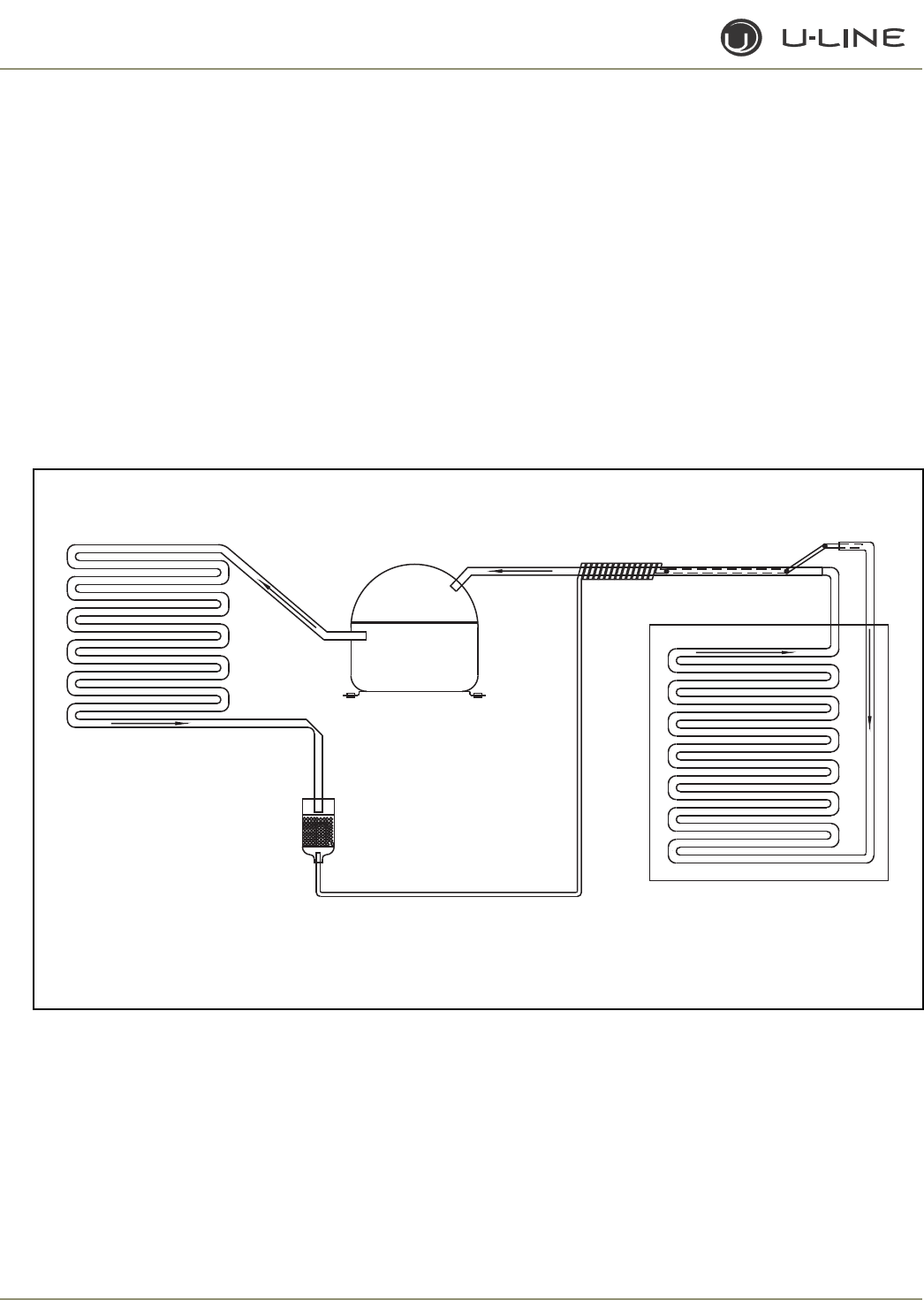
3-14
Section 3 - Service and Repair
2175R/2115R
2175WC/2115WC
2175BEV
2175DWRR/2275DWRWS
2275ZWC
(Includes Overlay Models)
GENERAL
Refrigerant is pumped from the compressor to the condenser as a
high pressure, high temperature vapor.
As the refrigerant cools in the high pressure condenser, the vapor
condenses to liquid. During this phase change, a great amount of
heat is rejected with the help of the condenser fan.
The liquid then flows to the dryer where it is strained and filtered.
From the dryer, the refrigerant flows through the capillary tube
which meters the liquid refrigerant to the evaporator. The
pressure of the refrigerant is reduced to the evaporating or low
side pressure.
The reduction of pressure on the liquid refrigerant causes it to boil
or vaporize until it reaches saturation temperature. As the low
temperature refrigerant passes through the evaporator coil, it
continues to absorb a lot of heat, causing the boiling action to
continue until the refrigerant is completely vaporized. It is during
this phase that the most heat is absorbed (the cooling takes place)
in the refrigerator.
The refrigerant vapor leaving the evaporator travels through the
suction line to the compressor inlet. The compressor takes the
low pressure vapor and compresses it, increasing both pressure
and temperature. The hot high pressure gas is pumped out the
discharge line and into the condenser. The cycle continues
Figure 9. 2175R/2115R/2175WC/2175BEV/2275DWRR/2175DWRR
CAPILLARY TUBE
DRYER
CONDENSER
COMPRESSOR
EVAPORATOR
ULIN_0280_A
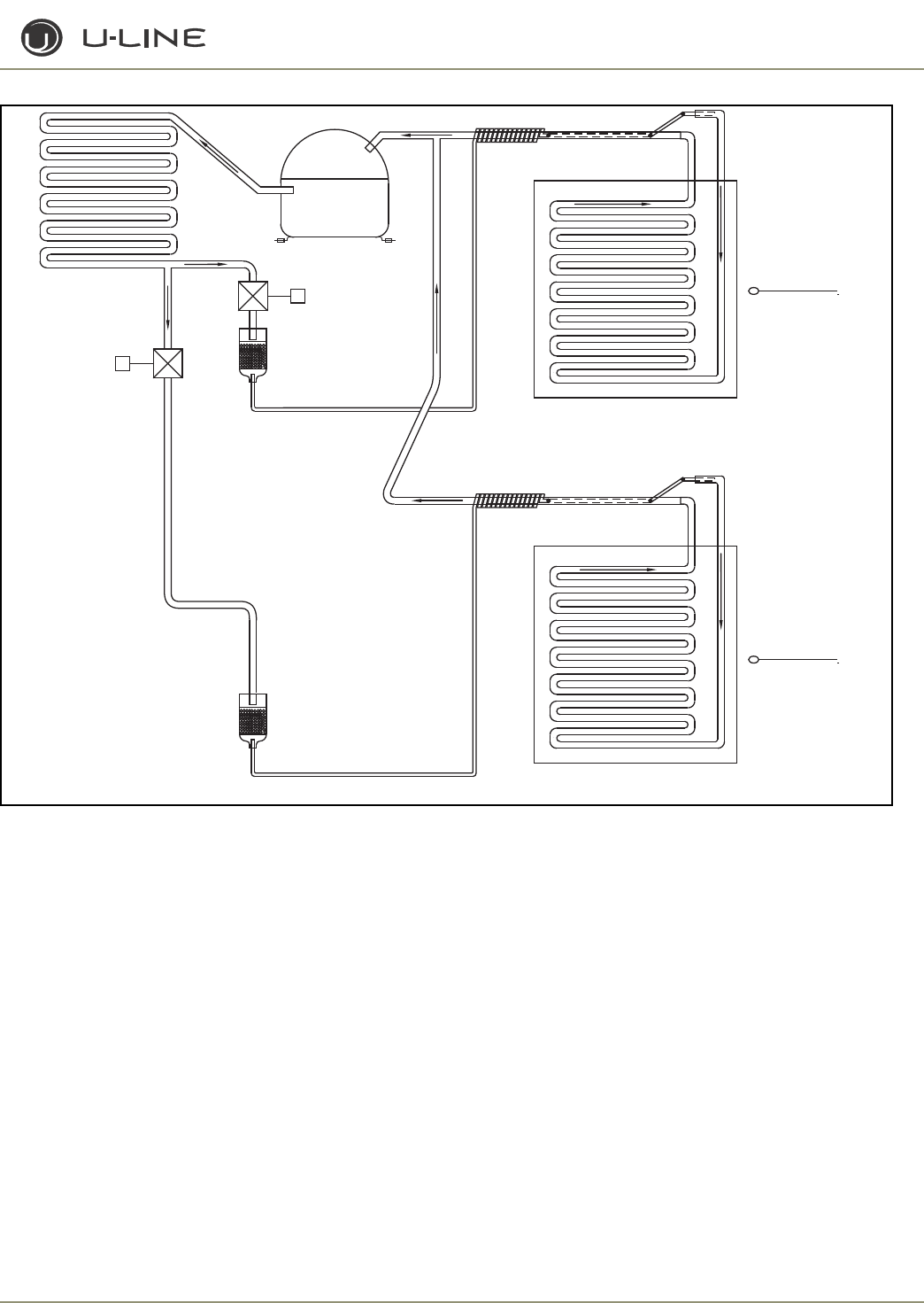
3-15
Section 3 - Service and Repair
Figure 10. 2275DWRWS/2275ZWC
REVIEW THE FOLLOWING NOTES FOR GENERAL
INFORMATION.
• The unit is equipped with a four-minute compressor-off cycle.
• The mullion heater is energized on the 2175DWRR whenever the
T3 temperature falls below 90°F.
Normal defrosting is based on a time and temperature scale. See
chart on page 3-40. Defrost ends if evaporator thermistor reaches
stop point or maximum time, whichever comes first.
THERMISTOR OUTAGE (EXCEPT DWRWS & 2275ZWC):
If the refrigerator thermistor (T1) fails, the unit will continue to
operate based on a preset time interval of 10 minutes on and 30
minutes off. The display will show “ER.”
If the evaporator thermistor (T2) fails, the unit will operate except it
will defrost solely on time and ignore the temperature reading. The
display will show “ER.” If the ambient thermistor (T3) fails, the unit
will always have the mullion heater energized. The display will show
“ER.”
THERMISTOR OUTAGE (DWRWS & 2275ZWC)
If T1 is not working, unit runs a preset time interval —
10 minutes ON, 60 minutes OFF.
If T2 is not working, unit runs a preset time interval —
10 minutes ON, 60 minutes OFF.
If either T3 or T4 is open, use 90 minutes for defrost length. These
errors do not show on the display; they are only logged on the board.
SERVICE
To check to see which relays are currently operating, hold the
COLDER key and press the ON/OFF key three times. When entering
the sequence, keep the COLDER key pressed until you completely
release the ON/OFF key for the third time. The display will cycle
through a series of numbers to tell which relays are energized. For
example, if the unit was cooling the bottom drawer the display would
show 11 20 31 40 50 61 70. The first number is the relay number. In
the second number, 1 means ON and 0 means OFF. The relay
information can be found in the Control Section.
Each relay can also be turned on and off individually to determine
whether or not the board and component are operating. If a board is
CAPILLARY TUBE
SOLENOID VALVE
SOLENOID VALVE
DRYER
CONDENSER
COMPRESSOR
EVAPORATOR
TOP
COMPARTMENT
THERMISTOR
CAPILLARY TUBE
DRYER
EVAPORATOR
DWR052
BOTTOM
COMPARTMENT
THERMISTOR
CAPILLARY TUBE
SOLENOID VALVE
SOLENOID VALVE
DRYER
CONDENSER
COMPRESSOR
EVAPORATOR
TOP
COMPARTMENT
THERMISTOR
CAPILLARY TUBE
DRYER
EVAPORATOR
DWR052
BOTTOM
COMPARTMENT
THERMISTOR

3-16
Section 3 - Service and Repair
suspected of not operating correctly, you can run through this
sequence to ensure each component is turning on and off through
the board correctly. Go into service mode and choose option #22.
This will cycle every relay on and off showing 10 11 20 21 …. If a
component fails to turn on when the relay does, you can verify if
there is voltage present by using a voltmeter to check the board
output. 1 means ON and 0 means OFF.
To view the actual refrigerator (T1) temperature, hold the WARMER
key until the actual temperature is displayed. To view the actual
thermistor readings for 2-4, hold the WARMER and COLDER keys
for about five seconds. The display will cycle through the three
thermistors and their temperatures. If a thermistor is unused in a unit
it will show a “0” reading.
In the general section the methods to enter some other service
modes are available.
TROUBLESHOOTING:
Error Codes
E1, E2, E7,
E8 & E9 Bad thermistor errors. Replace thermistor. Check for
thermistor errors by accessing “View thermistor #
status (2, 19, 20, or 21).” If the error code is repeated,
the thermistor is open or shorted. If a temperature is
displayed, the thermistor is not defective.
E3 This will be accompanied by a beep every minute. This
signals that the door (or bottom drawer) has been left
open for longer than 20 minutes. Close the door to
reset. If the light and display do not go off when the
door is closed, check to make sure the magnet is
positioned properly.
E5 This signals that the unit has been above set-point for
more than twelve hours by at least 10°. If the unit was
just plugged in, leave for 24 hours to see if the problem
is corrected. If it is not corrected, it is most likely a
refrigeration system issue.
E6 This signals that the refrigerator section has been at
least 10° below set-point for at least twelve hours. This
would most likely be caused by a bad relay and the
circuit board.
E10 This will be accompanied by a beep every minute. This
signals that the top drawer has been left open for
longer than 20 minutes. Close the door to reset. If the
light and display do not go off when the door is closed,
check to make sure the magnet is positioned properly.
After checking the errors, be sure to clear the error log by
performing service option 12.
Excessive Frost on evaporator
Force a defrost cycle via the keypad input or shut down unit and thaw
if frost is very thick. If the evaporator clears, it was due to some type
of abnormal operation. If the unit will continue to be used in this
manner, the defrost length can be lengthened in the service menu to
prevent future issues. Extending this length may be detrimental to the
refrigerator temperature. During very long defrosts the temperature
may raise higher than desired.
During the forced defrost no heating will occur. This is just a
prolonged off cycle.
Noise
Some noise is normal such as a hum from the fans/compressor.
Display is showing something other than “SP (38)” or
“ER.”
Push one of the keys to see if the display is reset.
Turn unit on and off via the display pad.
Unplug unit, wait one minute and plug back in. If any of these steps
returns the unit to operation, the unit was probably accidently
entered into a service mode.
Display is showing a random snaking of characters or a
degree symbol is flashing.
The unit is in a special showroom mode. Hold the COLDER key and
press the LIGHT key three times to exit.
Display not illuminating but unit operating
First try to plug and unplug the unit. If the display still does not
illuminate there is a four-wire pin connector running from the main
board in the base to the display board. One of the wires is
disconnected or damaged.
Unit is not operating—no cooling—no fans.
Unplug unit and plug back in. If main boards beeps when plugging in
the unit then this is most likely a system problem, not a board issue.
If board does not beep when plugging in the unit, check the power
supply to ensure the outlet is working. Also, check the fuse on the
circuit board.
Refrigerator too warm
Check the actual refrigerator temperature. If set to 38°F, the actual
temperature should be between 36°F and 40°F during normal
operation. Recent door openings, product loading or defrost cycles
will push the temperature higher for short time periods.
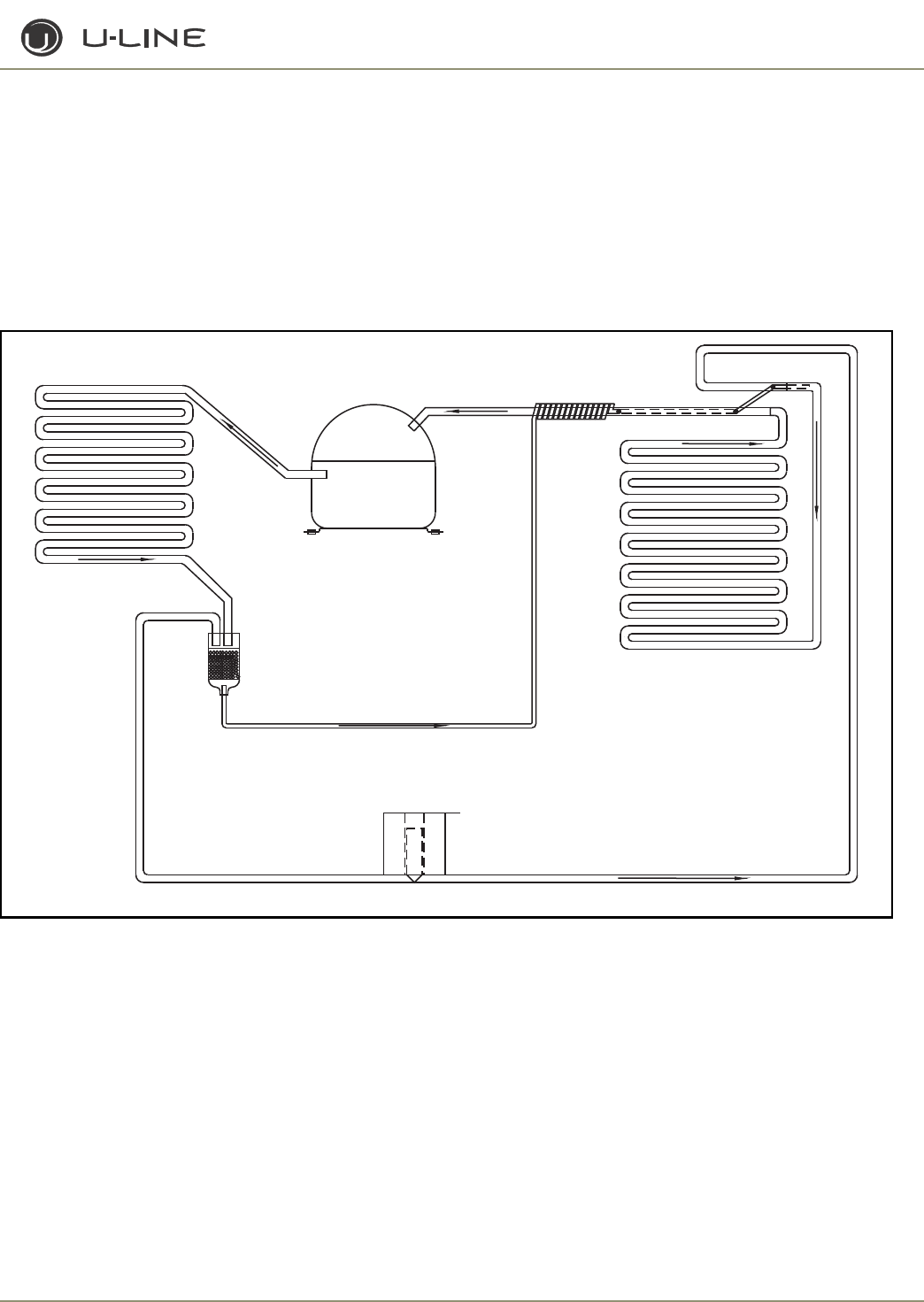
3-17
Section 3 - Service and Repair
CO2175F/2175RF/CO2175DWR
GENERAL
U-Line Frost Free Refrigeration System
Cooling Mode:
• Bypass solenoid valve closed
• Evaporator fan operating
• Refrigerant flows through capillary tube
• Normal vapor/compression cycle refrigeration
• Drain heater off (CO2175F/2175RF only)
Defrost Mode:
• Bypass solenoid valve open
• Refrigerant flows through bypass system
• Vapor flows from condenser to evaporator without a phase
change
• Drain heater on (CO2175F/2175RF only)
Figure 11. Frost Free Refrigeration System.
SOLENOID VALVE
CAPILLARY TUBE
VALVE IS CLOSED
FLOW WHEN SOLENOID
DRYER
CONDENSER
COMPRESSOR
EVAPORATOR
VALVE IS OPEN
FLOW WHEN SOLENOID
ULIN_0369_A
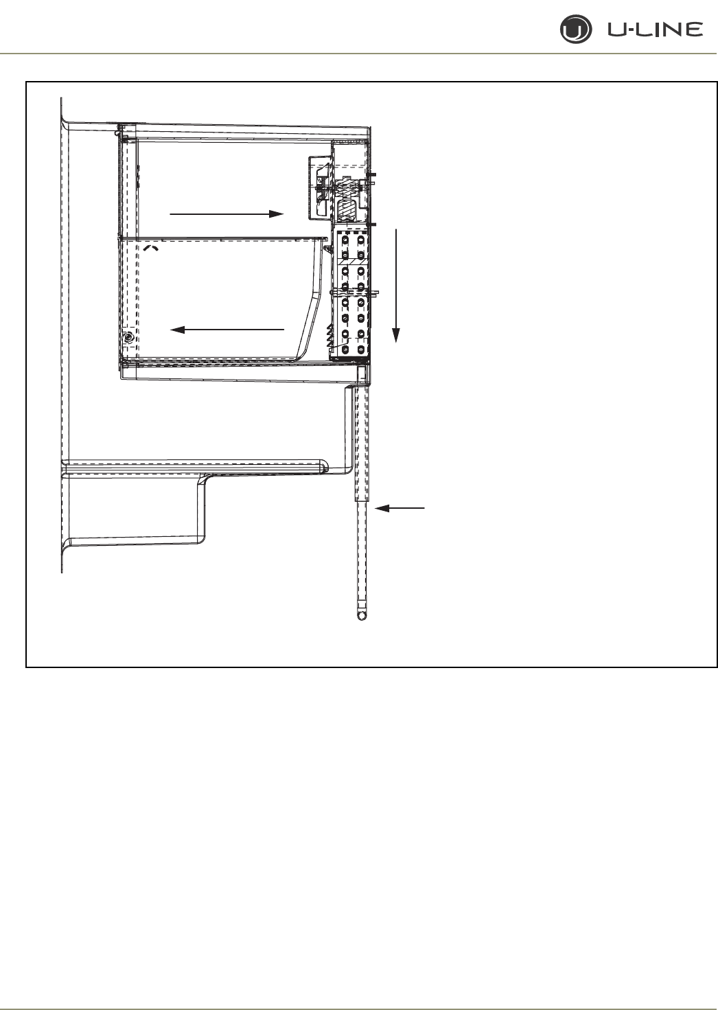
3-18
Section 3 - Service and Repair
Figure 12. CO2175R & 2175RF Only: Typical Frost Free Airflow Configuration
THERMISTORS
Three or four thermistors are employed. All are of the type 2.
These measure the refrigerator, freezer, ice maker, or evaporator
drain pan.
REED SWITCH
A reed switch is mounted to the underside of the cabinet and a
magnet is mounted to the door. When the door is closed the
magnet trips the switch which turns the light and display off.
For the CO2175DWR model there is a second reed switch
mounted on the inside rear left corner of the top drawer.
Both drawers are monitored individually; however, when either
drawer is opened both cabinets light and the displays energize.
DEFROST
These units defrost on time and temperature. The Defrost Cycle
runs for a minimum of 18 minutes (adjustable), and stops at a
maximum of 45 minutes or when T4 reaches 42°F (non-
adjustable), whichever comes first.
Air flow in at
evaporator blade
Air passes though
fin tube evaporator
Condensate drains down trough under
evaporator, into drain pan, and into
condensate pan through drain hose. The
drain trough is warmed during defrost by
contact with evaporator fins and drain
heater attached to the drain pan.
Air flow out at
evaporator outlet
ULIN_0370_A
3-19
Section 3 - Service and Repair
ICE MAKER
WARNING
DO NOT cycle ice maker by hand. This will cause
damage to the ice maker.
Freeze cycle
• Neither ice maker relay is energized.
• Unit is cooling down to 15°F set-point.
• The unit may cycle on and off as the ice maker is pulling
down to maintain the proper refrigerator/freezer
temperatures.
• The minimum freeze time as permitted by the board is 20
minutes (CO2175F) or 75 minutes (CO2175DWR).
Harvest cycle 1
• Relay 6 is energized for 30 seconds and relay 7 is energized
for 10 minutes. The bin arm must be fully lowered and the
lower drawer closed for this cycle to begin.
Harvest cycle 2
• The lower drawer must remain closed for the cycle to
continue. In the event that it is opened the timers will hold
until the drawer is closed. At that time they will resume the
cycle. If the unit has a door rather than a drawer it is not
effected.
• Relay 6 is now off and the ice maker is powered completely
by relay 7. This occurs at approximately the 2 o'clock
position.
• Ejector blades stall on the ice until the heater releases it
from the mold.
• This cycle will last a few minutes.
Water fill cycle
• At about the 10 o'clock setting the water valve is energized
for about 7 seconds to refill the mold.
• At the conclusion of the cycle the blades stop at the 12
o'clock position.
Harvest cycle 3
• Following the water fill relay 7 remains energized for the
balance of the 10 minutes that it needs to remain on.
Storage mode
• The bin arm is in the UP position, either held in place by the
ice or manually raised. The board continues to signal the ice
maker to harvest so relays 6 and 7 will energize; however,
with the arm up the cycle will not begin.
Review the following notes for general information before
reading the schematics.
These are some additional general notes and exceptions:
• The unit is equipped with a four-minute compressor off
cycle.
• The controller is designed to be able to show and set the
refrigerator set-point. Based on this input the controller
tries to maintain the perfect balance of refrigeration to keep
the refrigerator and freezer at acceptable temperatures. For
this reason the refrigerator temperature may fluctuate from
34°F to 40°F depending on the freezer load. The freezer will
also float in a -10 to +10 range depending on the
refrigerator load and usage.
• The ice harvest will be initiated when the ice maker
temperature drops to 15°F. Through a built-in timer the ice
maker can only harvest once every 20 minutes (for
CO2175F) or 75 minutes (CO2175DWR) at a maximum so
if the temperature is at 15°F it will not necessarily cycle
depending on when the previous cycle had occurred.
• The drain pan heater will energize five minutes before and
after the hot gas portion of the defrost cycle (not on
CO2175DWR). This time is not included in the defrost total
length.
• If the unit is turned off while the ice maker is in a harvest
mode, the display will flash OFF while the ice is harvesting
— up to 10 minutes.
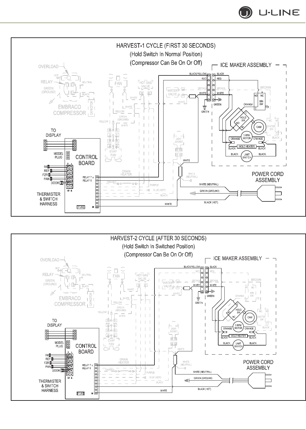
3-20
Section 3 - Service and Repair
Figure 13. CO2175F Harvest-1 Cycle (First 30 Seconds
Figure 14. CO2175F Harvest-2 Cycle (After 30 Seconds)
ULIN_0348a_A
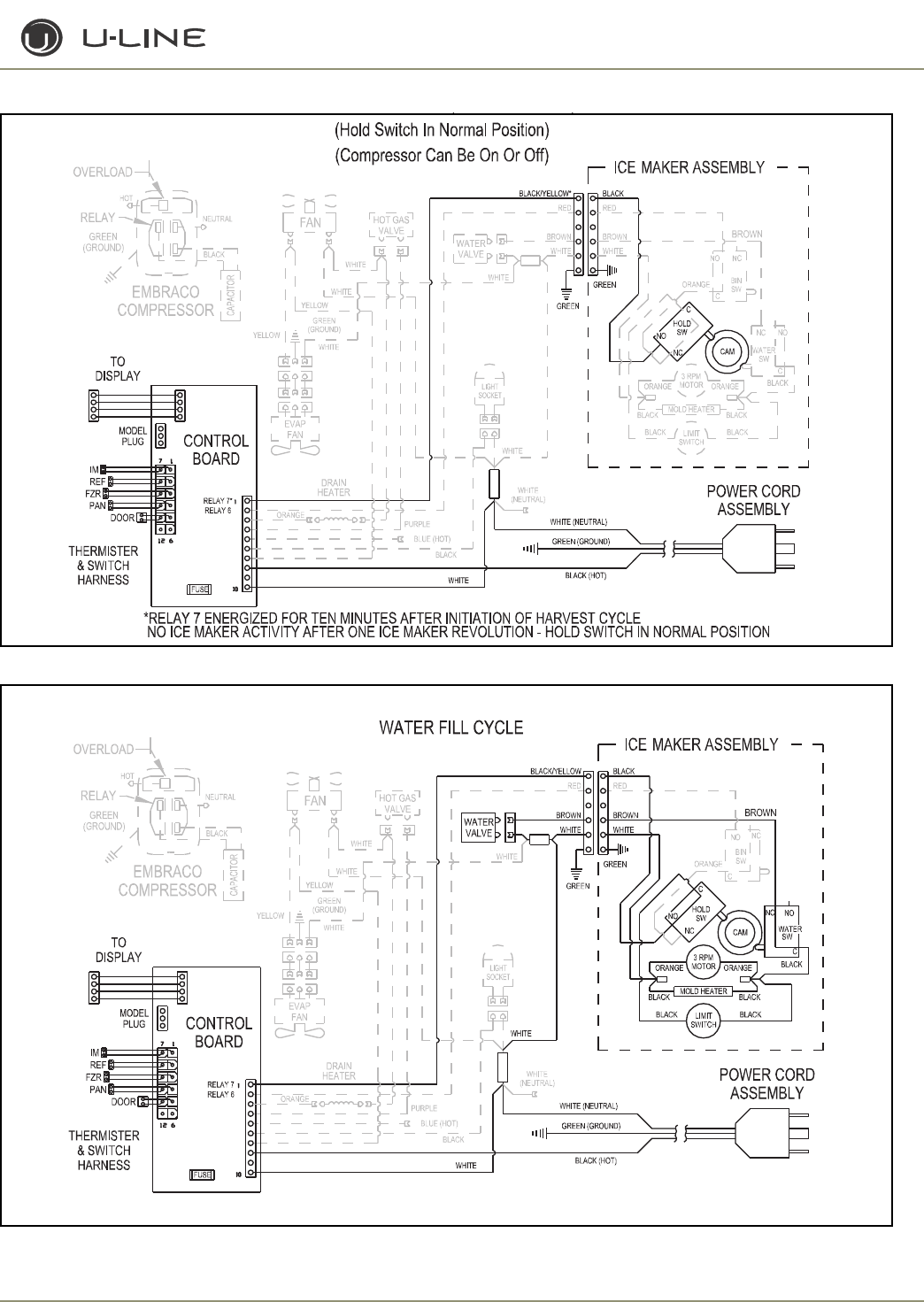
3-21
Section 3 - Service and Repair
Figure 15. CO2175F Harvest-3 Cycle (Post Harvest)
Figure 16. CO2175F Water Fill Cycle
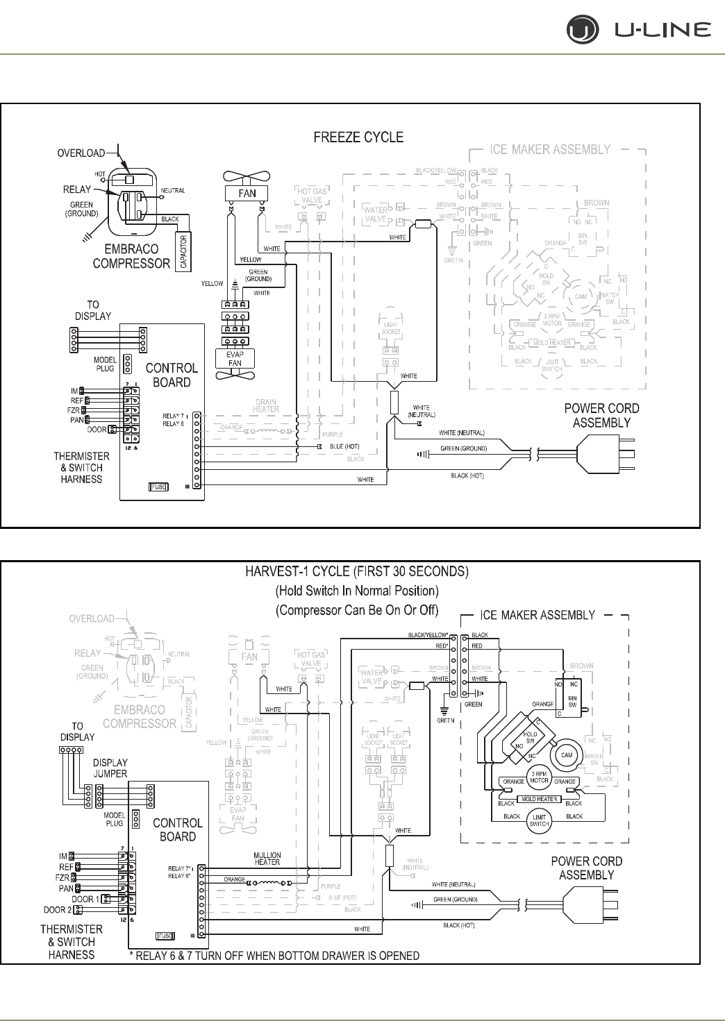
3-22
Section 3 - Service and Repair
Figure 17. CO2175F Freeze Cycle
Figure 18. CO2175/2275DWR Harvest-1 Cycle (First 30 Seconds)
ULIN_0350a_A
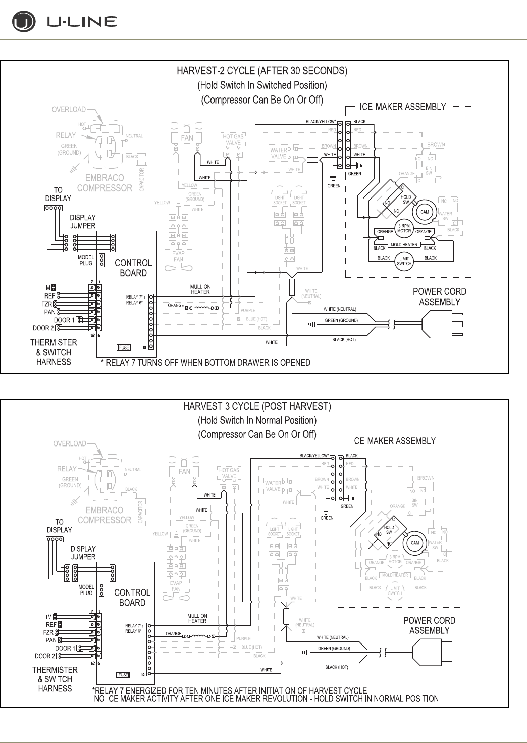
3-23
Section 3 - Service and Repair
Figure 19. CO2175/2275DWR Harvest-2 Cycle (After 30 Seconds)
Figure 20. CO2175/2275DWR Harvest-3 Cycle (Post Harvest)
ULIN_0345_A
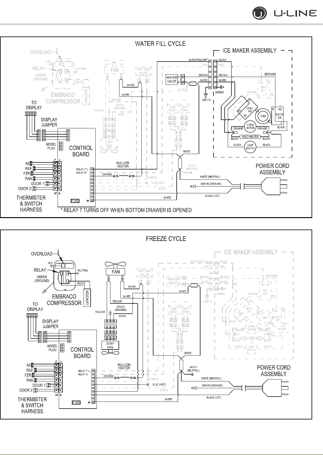
3-24
Section 3 - Service and Repair
Figure 21. CO2175/2275DWR Water Fill Cycle
Figure 22. CO2175/2275DWR Freeze Fill Cycle
ULIN_0346_A
ULIN_0347_A

3-25
Section 3 - Service and Repair
THERMISTOR OUTAGE
If the refrigerator thermistor (T1) fails, the unit will continue to
operate based on the freezer temperature. Cycle lengths and
temperatures may not be exact; however, this will prevent the loss of
perishables. The display will show “ER.” The exact error can be
accessed via the service mode.
If the ice maker thermistor (T2) fails, the unit will operate except it
will not produce ice. The display will show “ER.” The exact error can
be accessed via the service mode.
If the freezer thermistor (T3) fails, the unit will continue to operate
based on the refrigerator (T1) temperature. Cycle lengths and
temperatures may not be exact; however, this will prevent the loss of
perishables. The display will show “ER.” The exact error can be
accessed via the service mode.
If the pan thermistor (T4) fails, the unit will operate normally;
however, the defrost will take place on time only rather than time/
temperature. The display will show “ER.” The exact error can be
accessed via the service mode.
SERVICE
To check to see which relays are currently operating, hold the
COLDER key and press the ON/OFF key three times. When entering
the sequence, keep the COLDER key pressed until you completely
release the ON/OFF key for the third time. The display will cycle
through a series of numbers to tell which relays are energized. For
example, if the unit was in ice-making mode the display would show
11 20 31 40 51 60 70. The first number is the relay number. In the
second number, 1 means ON and 2 means OFF. The relay
information can be found in the Control Section.
Each relay can also be turned on and off individually to determine
whether or not the board and component are operating. If a board is
suspected of not operating correctly, you can run through this
sequence to ensure each component is turning on and off through
the board correctly. Go into service mode and choose option #22.
This will cycle every relay on and off showing 10 11 20 21 …. If a
component fails to turn on when the relay does, you can verify if
there is voltage present by using a voltmeter to check the board
output.
To view the actual refrigerator (T1) temperature, hold the WARMER
key until the actual temperature is displayed. To view the actual
thermistor readings for 2-4, hold the WARMER and COLDER keys
for about five seconds. The display will cycle through the three
thermistors and their temperatures. If a thermistor is unused in a unit
it will show a “0” reading.
In the general section the methods to enter some other service
modes are available. For these models some useful modes are the
ICE MAKER OFF MODE, FORCED ICE MAKER HARVEST, and
FORCED REFRIGERATOR DEFROST. These can be useful in
servicing the unit.
TROUBLESHOOTING:
Error Codes
E1, E2, E7, E8, E9 Bad thermistor errors. Replace thermistor.
Check for thermistor errors by accessing
“View thermistor # status (2, 19, 20, or 21).” If
the error code is repeated, the thermistor is
open or shorted. If a temperature is displayed,
the thermistor is not defective.
E3 This will be accompanied by a beep every
minute. This signals that the door (or bottom
drawer) has been left open for longer than 20
minutes. Close the door to reset. If the light
and display do not go off when the door is
closed check to make sure the magnet is
positioned properly.
E5 This signals that the unit has been above set-
point for more than twelve hours by at least 10
degrees. After repair is completed, leave for 24
hours to see if the problem is corrected. If it is
not corrected, it is most likely a refrigeration
system issue.
E6 This signals that the refrigerator section has
been at least 10 degrees below set-point for at
least twelve hours. This would most likely be
caused by a bad relay and the circuit board.
E10 This will be accompanied by a beep every
minute. This signals that the top drawer has
been left open for longer than 20 minutes.
Close the door to reset. If the light and display
do not go off when the door is closed check to
make sure the magnet is positioned properly.
After checking the errors be sure to clear the error log by
performing service option 12.
Not making ice
The ice maker needs to be down to 15°F before initiating a harvest. If
above 15°F, the unit is not cooling properly or has not been plugged
in for a sufficient period of time.
The CO2175DWR model will only harvest ice with the lower drawer
closed.
To check the operation of the circuit board and the ice maker, force
an ice harvest through the keypad input. During this time you can
check to see if the blades rotate, if they stop anywhere, if the water
valve opens, etc.

3-26
Section 3 - Service and Repair
Too much ice
Ensure the bin arm is correctly moving during an ice production
cycle and that it can touch the top of the ice. If not, the arm may
have been bent.
Excessive frost on evaporator
Force a defrost cycle via the keypad input. If the evaporator clears
it was due to some type of abnormal operation. If the unit will
continue to be used in this manner the defrost length can be
lengthened in the service menu to prevent future issues. Extending
this length may be detrimental to the freezer section by causing
food to melt or ice to fuse more easily.
During the forced defrost, if no heating occurs, check the hot gas
coil and heater for voltage and resistance.
Noise
These are frost-free units with two fans, compressor, and two
solenoid valves. Some noise is normal such as a hum from the fans/
compressor. Also, during an ice harvest it is normal to hear water
filling the mold and cubes dropping into the bucket.
Poor ice quality
This can be caused by poor incoming water quality.
Display is showing something other than “SP (38)”
or “ER.”
Push one of the keys to see if the display is reset.
Turn unit on and off via the display pad.
Unplug unit, wait one minute, and plug back in. If any of these
steps returns the unit to operation, the unit was probably
accidentally entered into a service mode.
Display is showing a random snaking of characters
or a degree symbol is flashing.
The unit is in a special showroom mode. Hold the COLDER key
and press the LIGHT key three times to exit.
Display not illuminating but unit operating
First try to plug and unplug the unit. If the display still does not
illuminate there is a four-wire pin connector running from the main
board in the base to the display board. One of the wires is
disconnected or damaged.
Unit is not operating—no cooling—no fans.
Unplug unit and plug back in. If main board beeps when plugging in
the unit, then this is most likely a system problem, not a board
issue.
If board does not beep when plugging in the unit, check the power
supply to ensure the outlet is working. Also, check the fuse on the
circuit board.
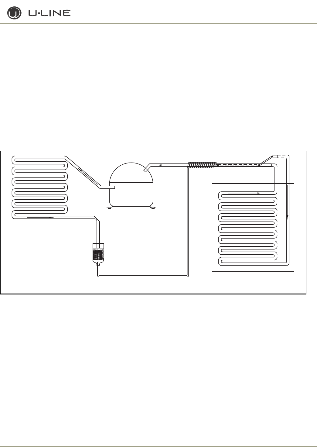
3-27
Section 3 - Service and Repair
1175R/1115R
1175WC/1115WC
1175BEV/ADA24R
GENERAL
Refrigerant is pumped from the compressor to the condenser as a
high pressure, high temperature vapor.
As the refrigerant cools in the high pressure condenser, the vapor
condenses to liquid. During this phase change, a great amount of
heat is rejected with the help of the condenser fan.
The liquid then flows to the dryer where it is strained and filtered.
From the dryer, the refrigerant flows through the capillary tube
which meters the liquid refrigerant to the evaporator. The
pressure of the refrigerant is reduced to the evaporating or low
side pressure.
The reduction of pressure on the liquid refrigerant causes it to boil
or vaporize until it reaches saturation temperature. As the low
temperature refrigerant passes through the evaporator coil, it
continues to absorb a lot of heat, causing the boiling action to
continue until the refrigerant is completely vaporized. It is during
this phase that the most heat is absorbed (the cooling takes place)
in the refrigerator.
The refrigerant vapor leaving the evaporator travels through the
suction line to the compressor inlet. The compressor takes the
low pressure vapor and compresses it, increasing both pressure
and temperature. The hot high pressure gas is pumped out the
discharge line and into the condenser. The cycle continues
Figure 23. 1175R/1115R/1175WC//1115WC1175BEV/ADA24R Normal Vapor/Compression Cycle
These are some additional general notes and exceptions: • The unit is equipped with a four-minute compressor off cycle.
CAPILLARY TUBE
DRYER
CONDENSER
COMPRESSOR
EVAPORATOR
ULIN_0280_A
3-28
Section 3 - Service and Repair
THERMISTOR OUTAGE
If the refrigerator thermistor (T1) fails, the unit will continue to
operate based on a preset time interval of 10 minutes on and 30
minutes off. The display will show “E1.”
TROUBLESHOOTING
Error Code
E1, E2 Bad thermistor errors. Replace thermistor. Check
for thermistor errors by accessing "View thermistor
# status (2)." If the error code is repeated, the
thermistor is open or shorted. If a temperature is
displayed, the thermistor is not defective.
E3 This signals that the door (or bottom drawer) has
been left open for longer than 20 minutes. Close the
door to reset. If the light and display do not go off
when the door is closed, check to make sure the
magnet is positioned properly.
E5 This signals that the unit has been above set-point
for more than twelve hours by at least 10 degrees. If
the unit was just plugged in, leave for 24 hours to
see if the problem is corrected. If it is not corrected,
it is most likely a refrigeration system issue.
E6 This signals that the refrigerator section has been at
least 10 degrees below set-point for at least twelve
hours. This would most likely be caused by a bad
relay and the circuit board.
After checking the errors be sure to clear the error log by
performing service option 12.
Excessive Frost on evaporator
Shut down unit and thaw if frost is very thick. The unit may be used
in an abnormal manner. If the unit will continue to be used in this
manner the defrost length can be lengthened in the service menu
to prevent future issues. Extending this length may be detrimental
to the refrigerator temperature. During very long defrosts the
temperature may rise higher than desired.
CAUTION
If frost is heavy, divert water from drain pan to prevent
water on floor.
Noise
Some noise is normal, such as a hum from the fans/compressor.
Display is showing something other than “SP (38)”
or “ER.”
Push one of the keys to see if the display is reset.
Turn unit on and off via the display pad.
Unplug unit, wait one minute, and plug back in. If any of these steps
returns the unit to operation the unit was probably accidentally
entered into a service mode.
Display is showing a random snaking of characters
or a degree symbol is flashing.
The unit is in a special showroom mode. Hold the COLDER key
and press the LIGHT key three times to exit.
Refrigerator too warm
Check the actual refrigerator temperature. If set to 38°F, the actual
temperature should be between 36°F and 40°F during normal
operation. Recent door openings, product loading, or defrost
cycles will push the temperature higher for short time periods.
3-29
Section 3 - Service and Repair
OPERATING ENVIRONMENTAL/
CLIMATE CONTROL
REQUIREMENTS
For All - Except WC, ADA, DWRWS, BEV
Center, CODWR & Dual Zone(Z)
Many U-Line models are designed to operate in harsh outdoor/
marine environments. Special considerations include the following:
• The units are designed to operate between 50°F (10°C) and
110°F (40°C). High ambient temperatures (110°F or higher) may
reduce the unit's ability to reach low temperatures and may also
reduce the ice production rate for those models with icemakers.
• If the ambient temperature is expected to drop below 45F, drain
all water from the unit to prevent freezing damage not covered by
the warranty.
• For best performance, keep the unit out of direct sunlight and
away from heat generating equipment.
• For best performance and life outdoors, place under a counter or
provide shelter of some kind.
• In climates where high humidity and dew points are present,
condensation may appear on outside surfaces. This is considered
normal. The condensation will disappear when the humidity
drops.
For WC, ADA, DWRWS, CODWR, BEV,
CLRCO & Dual Zone (Z)
Many U-Line models are designed to operate in harsh outdoor/
marine environments. Special considerations include the following:
• The units are designed to operate between 50°F (10°C) and
110°F (40°C). High ambient temperatures (110°F or higher) may
reduce the unit's ability to reach low temperatures.
• For best performance, keep the unit out of direct sunlight and
away from heat generating equipment.
• In climates where high humidity and dew points are present,
condensation may appear on outside surfaces. This is considered
normal. The condensation will disappear when the humidity
drops.
• U-Line does not recommend installation of glass front models
(Wine Captain® wine storage models and Beverage Centers) as
well as the CLRCO, Combo Drawer model (Refrigerator/Freezer/
Ice Maker) outdoors, or in tropical climates where high humidity
and dew point are present on a regular basis, unless air-
conditioning (typical 72°F, 75%RH) will be used.
ÉCHELON ELECTRONIC CONTROL
Échelon Keypad Options
DANGER
DANGER
Electrocution can cause death or serious injury. Take
precautions when touching a bare circuit board. Wear an anti-
static wriststrap and ground it to an electrical ground or
grounded water pipe. Handle circuit boards carefully and avoid
touching components.
NOTE: When touching key combinations in which you hold one key and
press another key three times, it is important to carefully follow the
procedure.
1. Hold the desired key ensuring the light above the key is lit.
2. Press the other key three times, ensuring it lights up each time.
3. Release the held key only after releasing the pressed key for the
third time.
Except as noted, these functions are available on all models.
ON/OFF
The ON/OFF mode allows the unit to be turned on and off via the
keypad. To do this, hold the key for approximately 10 seconds until
the “F” begins to flash. Release and the unit will switch modes. In
the OFF position the cabinet light will remain operational. This mode
does not disconnect power from the circuit board so it is still “live.”
Turning the unit off while in Clean, Ice Maker Off, Forced Harvest, or
Forced Defrost will cancel those modes. If this mode is entered while
a unit is in an ice-making harvest mode it will continue its cycle and
flash OFF until completed.
CABINET LIGHT
On units with glass doors, touching the light key will turn on the
cabinet light for four hours at a time. Touching the key again will turn
the light off. Using the cabinet light for more than four hours may be
detrimental to the cabinet temperature and product. Only available
on models 2115WC, 2175WC, 2275DWRWS and
2275ZWS/2275ZWCOL.
ADJUSTING THE SET-POINT
- ALL MODELS EXCEPT 2275DWRWS/2275ZWC/
2275ZWCOL
To adjust the set-point press and release either the WARMER or
COLDER key. This will start the set-point flashing. While in this
mode you can adjust the set-point warmer or colder until the desired
temperature is reached. The factory recommended set-point is 38°F
for refrigerators/refrigerator-freezers and 50°F for wine coolers.
When adjustment is complete, stop touching the display and the set-
point will be saved in approximately five seconds. Not available on
CLR2160.
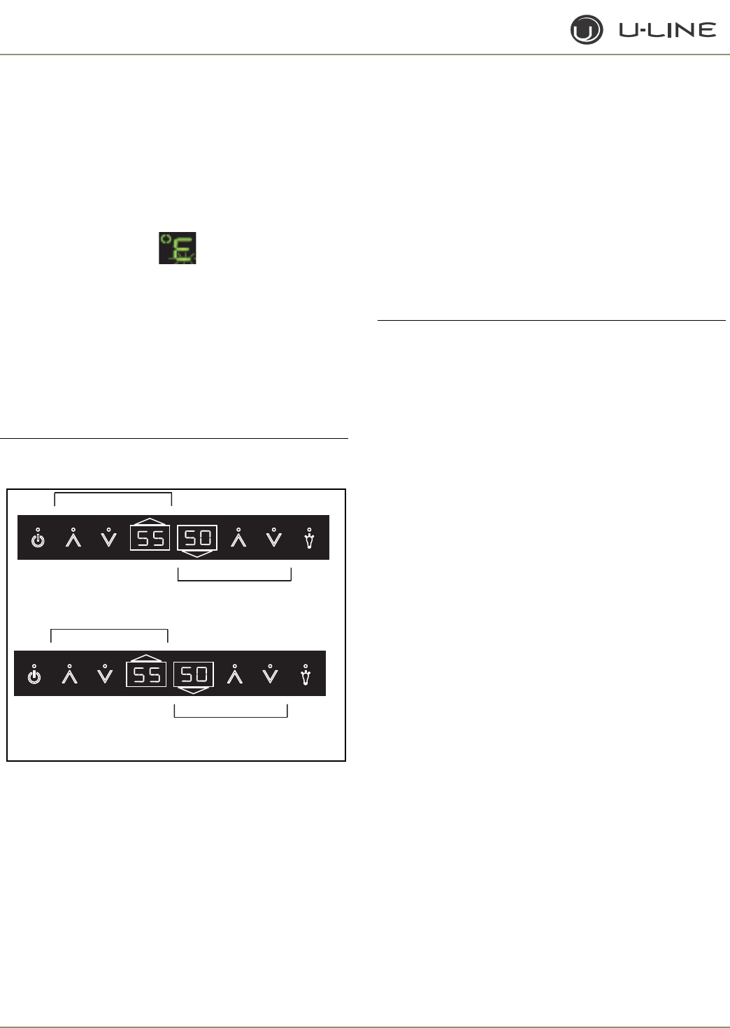
3-30
Section 3 - Service and Repair
ADJUSTING THE SET-POINT
- 2275DWRWS ONLY
1. Press and release the WARMER icon. The top of the F in °F of
the top drawer will begin to flash. This will allow you to adjust the
temperature of the top drawer. In 10 seconds of inactivity, the
bottom bar of the F in °F will begin to flash (see below); this will
allow you to adjust the temperature of the bottom drawer.
Adjustments to the lower drawer can be made immediately if the
LIGHT icon is pressed.
2. While the top or bottom bar of the F in
°F
is flashing, press the
WARMER or COOLER icon as required to adjust the set-point
temperature. The change will be set five seconds after adjusting the
temperature and the new set-point temperature will be displayed.
Allow the unit to sit for 10 seconds to return to normal mode.
ADJUSTING THE SET-POINT
- 2275ZWC/2275ZWCOL ONLY
IMPORTANT
IMPORTANT
Adjust the set-point temperature and wait 24 hours for the
temperature to stabilize before rechecking.
.
Figure 24. Adjusting Set-Point Temperature-2275ZWC/
2275ZWCOL
This default temperature is used by the controller to maintain the
temperature zones in your unit.
The default temperatures are a recommendation. If further
temperature adjustments are required, use the following procedure
to adjust the set-points.
1. Press and release the desired zone WARMER icon to put the
controller in the SET TEMPERATURE mode. The current range
symbol will show on the display (top, Figure 24).
Note: If no further action is taken, this mode will self cancel in five
seconds, and the original set-point temperature will be displayed.
2. Press the WARMER or COOLER icon to scroll to the desired
range (RW, WW, SW, BV).
3. When the desired range is displayed, press the LIGHT icon to
display the current set-point temperature
(bottom, Figure 24)
.
Note: Set-point temperature can only be changed when the decimal is
flashing.
4. When the decimal is flashing, press the WARMER or COOLER
icon as required to adjust the set-point temperature.
5. When the desired set-point is displayed, press the LIGHT icon.
The new set-point will show in the display.
6. Repeat for other zone display if required.
IMPORTANT
IMPORTANT
Whenever a zone range is changed (example: RW to WW),
it will revert to the factory default.
VIEWING ACTUAL TEMPERATURE
- ALL MODELS EXCEPT 2275DWRWS/2275ZWC/
2275ZWCOL
There are two modes to view temperature. In viewing temperature
in these modes, any offsets are taken into account. This means that if
you place a thermistor in a known temperature, let’s say ice water, it
may not read the 32°F that you would assume. If the control offset
was preset at -3°F while you placed the thermistor in an icebath, the
actual thermistor reading when viewing actual temperature would
read 35°F. In the unit this would cause the cabinet to push itself 3°
cooler. To view pure thermistor readings, you must go into the
service menu and choose the correct option.
To view T1 (normally refrigerator temperature) hold the WARMER
key for approximately five seconds until the “F” flashes. Release and
the display will show the corrected refrigerator temperature. For
Wine Cooler models the display will cycle through all three zones.
These temperatures are approximate and calibrated for a cabinet in
normal ambient temperatures with some product load. Checking a
completely unloaded cabinet may result in other temperatures. Not
available on CLR2160.
To view T2-T4, hold both the WARMER and COLDER keys for
approximately five seconds until the first thermistor reading appears.
At this time the display will cycle through thermistors 2-4 and their
accompanying readings. If a thermistor is not used on that particular
model, it will show “0” and if the thermistor is not working, it will
show an ER.
ULIN_1009_A
☛
ULIN_1012_A
☛
LOWER ZONE CONTROLS
Light
Display
Power Warmer
Warmer
Cooler
Cooler
Display
UPPER ZONE CONTROLS
LOWER ZONE CONTROLS
Light
Display
Power Warmer
Warmer
Cooler
Cooler
Display
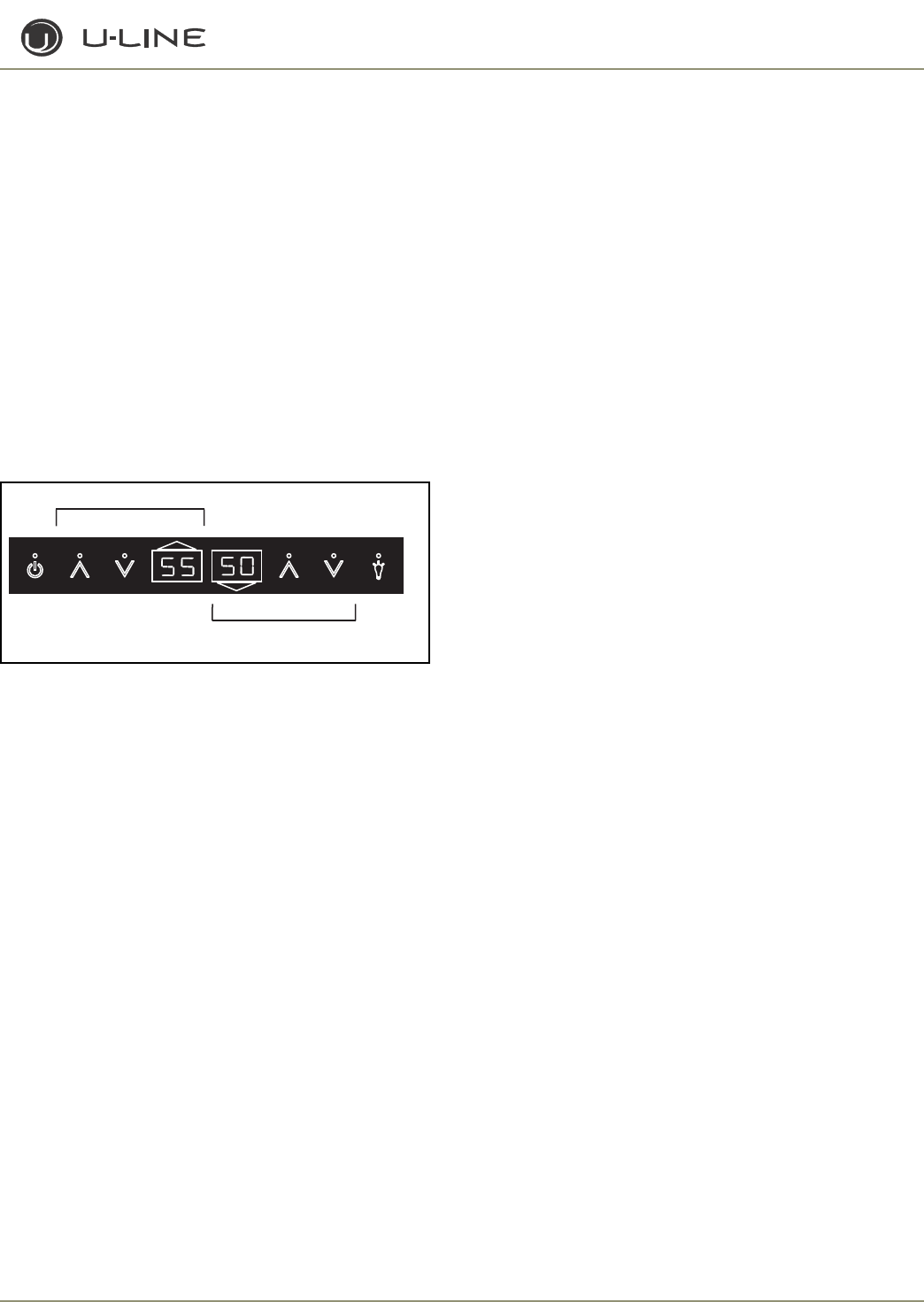
3-31
Section 3 - Service and Repair
VIEWING ACTUAL TEMPERATURE
- 2275DWRWS ONLY
To view the temperature in the top and bottom drawer (T1 and
T2), hold the WARMER key for five seconds until “°F” flashes.
Release and the display will show the corrected temperatures of
both zones on their respective displays. To view the temperature
of T3 and T4, you must use the service mode.
VIEWING ACTUAL TEMPERATURE
- 2275ZWC/2275ZWCOL ONLY
To display actual zone temperatures (not set-point):
1. Press and hold the WARMER icon for the desired zone for
approximately five seconds until unit beeps, and release when
the decimal in the display begins to flash (Figure 25).
2. The display will show the actual zone temperature.
3. After five seconds, the display will return to the set-point
temperature.
Figure 25. Displaying Zone Temperature
CHANGING FROM FAHRENHEIT TO CELSIUS
To change the displayed temperature from °F to °C, hold the
LIGHT key and press the down arrow three times. This will change
all values to °C. When the key combination is accepted the control
will beep once and change values.
SHOWROOM MODE
This mode is designed to show units in a display environment.
When in this mode the only functions will be the control and
cabinet lights. The compressor, fans, etc. will not operate. To enter
this mode hold the down arrow and press the LIGHT button three
times. When entered, the unit will beep once and the degree
symbol will begin to flash. When the degree symbol is flashing the
unit will allow the use of the control for demonstrations.
On early models, after not touching the unit for one minute the
display will begin to “snake” around. This is meant to alert you the
unit is in showroom mode.
On later models, the degree (°) flashes.
The unit can be left in this mode indefinitely. If you again want to
demo the control, touch any key and the degree symbol will begin
to flash. To exit this mode: If using software version 2.8, this mode
will exit automatically when the unit is unplugged. If using software
version 2.9, this mode needs to be exited by the same key
combination as used to enter the mode.
SERVICE MODE
This mode has 27 different options available for service diagnostics.
To enter the mode hold the WARMER key and press the LIGHT
button three times. The display will show “0” and the board will
beep once. When in this mode the WARMER and COLDER keys
will act as up and down arrows to select the desired option. The
LIGHT key is the ENTER key and will enter a function. If changing a
function, you must press the LIGHT button again to retain the
changed setting. To exit the service mode, scroll to option 99 and
press the LIGHT key. After five minutes of not touching any keys
the mode will also exit automatically.
DISPLAY TOGGLE
On glass door units the display normally stays on all the time. To
have the display turn off with the door press the up arrow and
touch the ON/OFF key three times. The °F sign will flash and the
board will beep once to let you know the mode has been accepted.
This mode can be toggled on or off by the same key combination.
To see if the display should be staying on 100% or turning off with
the door, you can check service option 8. Only available on
2115WC, 2175W, 2275DWRWS, 2175BEV, 2275ZWC &
2275ZWCOL.
BLACKOUT MODE
Hold the LIGHT key for 10 seconds until the °F starts flashing.
When released, the unit will beep once and the display and cabinet
light will shut off. To cancel this mode, hold the LIGHT key again
for about 10-12 seconds.
CLEAN CYCLE
To enter the self-cleaning cycle hold the ON/OFF key and press
the light three times. The unit will beep once and the display will
show CL. Follow the cleaning instructions. At the conclusion of
this mode (1 hour) the display will revert to set-point and the unit
will resume normal operation. To cancel this mode turn the unit
off via the keypad. Only available on CLR2160 and
CLRCO2175.
ICE MAKER OFF MODE
This mode will stop ice production. To enter hold the ON/OFF key
and press the up arrow three times. The unit will beep once when
the mode is entered. After 5-10 seconds the display will start to
scroll from “SP” to “Ice” to “Off” as long as the mode is active. To
exit either turn the unit off via keypad or do the same key
combination. Only available on CO2175F, CLRCO2175 and
CO2175DWR.
FORCED HARVEST
This mode can be used to force ice to harvest from the mold. To
enter this mode hold LIGHT key and press the up arrow three
times. The unit will initiate an ice harvest. There is no audible tone
when entering this mode. Only available on CO2175F and
CO2175DWR.
ULIN_1011_A
☛
UPPER ZONE CONTROLS
LOWER ZONE CONTROLS
Light
Display
Power Warmer
Warmer
Cooler
Cooler
Display

3-32
Section 3 - Service and Repair
FORCED DEFROST
This will allow the unit to defrost quickly. For R and WC units, this is
just an off cycle. For units with hot gas defrost the unit will enter a
hot gas defrost per the specification. Hold the LIGHT key and press
ON/OFF three times. The unit will beep once when entering this
mode. To exit this mode either do the same key combination or turn
the unit off via the display. Not available on CLR2160.
ICE THICKNESS ADJUST
This will allow addition or subtraction of up to five minutes from the
ice-making cycle. To enter this mode hold the up arrow and press the
down arrow three times. The unit will beep once and display the
current ice thickness. To adjust up or down use the arrows. Press
LIGHT key when completed. Please refer to the ice thickness section
of the manual to view proper cube sizes and recommendations.
Only available on CLR2160 and CLRCO2175.
TEMPORARY SHUTDOWN/OFFICE MODE
In some cases it may be requested for the unit to be shut down for
short periods during meetings for example. To do this hold the down
arrow and press the up arrow three times. The unit will beep once
and show OFF on the display. This mode can be canceled by
removing power from the unit or turning it on via the display. The
mode will automatically be changed back to ON after three hours.
Only available on CLR2160 and CLRCO2175.
RELAY STATUS
To see which relays are operating, hold the down arrow and hit ON/
OFF three times. The unit will scroll through all relays and whether
they are on or off. See specific unit section for explanation.
MODEL NUMBER CHANGE
Only the main circuit board requires model number selection. The
display board is universal and will automatically adapt to the unit it is
plugged into. The model number can be changed with the board
installed or uninstalled from the unit. To program uninstalled you will
need a display board and a power supply. For the power supply hook
a neutral wire up to pin 10 and a 120V wire to pin 8 of the circuit
board.
1. Plug in unit.
2. The display may show a SP or --, either is OK.
3. Install a jumper on J3. The jumper can be obtained from U-Line P/
N 68080.
4. Hold down WARMER, COLDER and LIGHT buttons until display
shows model number and main board beeps.
5. Use WARMER/COLDER to select new model number.
61-2175R 120V 75-2175R 220V
62-2175WC 120V 76-2175WC 220V
63-2175BEV 120V 77-2175BEV 220V
64-CO2175F 120V 78-CO2175 220V
65-2175RF 120V 79-2175RF 220V
66-CO2175DWR 120V 80-CO2175DWR 220V
67-CLR2160 120V 81-CLR2160 220V
68-CLRCO2175 120V 82-CLRCO2175 220V
70-2175DWR 120V 85-2275DWRWS 120V
71-2115R 120V 86-2275DWRWS 220V
72-2115WC 120V 87-2275ZWC 120V
73-2115R 220V 88-2275ZWC 220V
74-2115WC 220V
6. Press and release LIGHT key.
7. Wait for display to stop flashing.
8. Remove jumper from board.
9. Unplug unit and wait five seconds.
10. Plug unit back in.
Échelon Service Menu
Enter service menu by holding up arrow and pressing LIGHT three
times. Select option 1 to 27 with the up and down arrows. To enter
the option, press the LIGHT key. If changing a setting, you must press
the LIGHT key again to retain the changed setting.
When entering service mode all other modes are cancelled and the
unit will stop operating. When exiting service mode the unit will
begin to operate normally, however the four-minute compressor off
cycle still applies.
1. Light all LED segments.
This will illuminate all the LEDs on the board to ensure they work
properly.
2. Thermistor 1 status—Temperature, E1, or E2.
This will show the pure thermistor reading with no offsets taken
into account. When placed in ice water this thermistor should
read 32°F in this menu option. Not available on CLR2160.
3. Error log
A list of the errors in the order they occurred will scroll once on
the display. Repeat if desired. Once viewed perform option 12 to
clear the errors from memory.
4. Defrost information
Displays the number of defrosts that have occurred in the past 24
hours.
5. Compressor runtime based on last cycle
This will show the number of minutes the compressor has run in
the prior cycle (or current cycle if the compressor was running
when service mode was entered).
6. Defrost length adjustment—up to 99 minutes
The length of the defrost can be adjusted up to 99 minutes long.
The other defrost parameters still apply. Lengthening a defrost
may cause higher than normal temperatures in the refrigerator
section. Not available on CLR2160.
7. Light switch 1 status—0 or 1
This will tell if the light should turn off with the door switch or
not. At the “0” reading the light should be off with the door
closed and on with the door open. At the “1” reading the light
stays on always.
8. Display toggle status—0 or 1
This will tell if the display should turn off with the door switch or
not. At the “0” reading the display should be off with the door
closed and on with the door open. At the “1” reading the display
stays on always.
9. Restore factory defaults
This will restore the default set-point, defrost and offset values.
10. Adjust thermistor 1 offset—10 to +10F

3-33
Section 3 - Service and Repair
This allows calibration of the sensor to cabinet for abnormal
operations. By adjusting this number colder you can change the
average cabinet temperature to a colder value. Not available
on CLR2160.
11. Data download
Along with the separate ESPY software you can download the
rolling data file.
12. Clear error log
Perform this operation after checking the errors.
13. Clear download memory
Clears the rolling data file if desired.
14. Model number displayed
Displays the two-digit model number of the specific unit.
15. Adjust thermistor 1 differential
This number should not be adjusted. Not available on
CLR2160.
16. Adjust thermistor 2 offset
This allows calibration of the sensor to cabinet for abnormal
operations. By adjusting this number colder you can change the
average cabinet temperature to a colder value. Not available
on 2175RF.
17. Adjust thermistor 3 offset
This allows calibration of the sensor to cabinet for abnormal
operations. By adjusting this number colder you can change the
average cabinet temperature to a colder value. Not available
on Rs, WCs or CLR2160.
18. Adjust thermistor 4 offset
This allows calibration of the sensor to cabinet for abnormal
operations. By adjusting this number colder you can change the
average cabinet temperature to a colder value. Not available
on Rs or WCs.
19. Thermistor 2 status
This will show the pure thermistor reading with no offsets
taken into account. When placed in ice water this thermistor
should read 32°F in this menu option. Not available on
2175RF.
20. Thermistor 3 status
This will show the pure thermistor reading with no offsets
taken into account. When placed in ice water this thermistor
should read 32°F in this menu option. Not available on Rs,
WCs or CLR2160.
21. Thermistor 4 status
This will show the pure thermistor reading with no offsets
taken into account. When placed in ice water this thermistor
should read 32°F in this menu option. Not available on Rs,
WCs or CLR2160.
22. Automatic toggle through relays switch on and off
See specific unit section for description.
23. Defrost interval adjust. 3 to 24 hours
This will adjust the interval between defrosts from 3 to 24
hours. Adjusting from the factory settings may cause undesired
temperature in the refrigerator section.
24. Adjust thermistor 2 set-point. Only available on
CO2175F, CO2175DWR, CLR2160 and CLRCO2175.
25. Adjust thermistor 3 set-point. Only available on
2275DWRWS.
26. Adjust thermistor 4 set-point. Only available on
2275DWRWS.
27. Show software revision
This will toggle between main and display board software
revision. The main board number will be accompanied by the
degree symbol.
Error Codes
E1 Thermistor 1 is open. Not available on CLR2160.
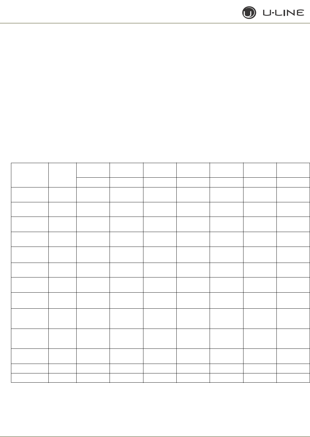
3-34
Section 3 - Service and Repair
E2 Thermistor 1 is shorted. Not available on CLR2160.
E3 Main door or bottom drawer is open longer than 20 minutes.
Not available on CLR2160.
E4 Compressor had 100% runtime between two defrost cycles.
Does not show on display—only in error log.
E5 Thermistor 1 out of range + 10°F for more than 12 hours.
Not available on CLR2160.
E6 Thermistor 1 out of range -10°F for more than 12 hours.
Not available on CLR2160.
E7 Thermistor 2 open or shorted. Not available on 2175RF.
E8 Thermistor 3 open or shorted. Not available on Rs, WCs
or CLR2160.
E9 Thermistor 4 open or shorted. Not available on Rs, WCs
or CLR2160.
E10 Top drawer is open longer than 20 minutes. Only available
on drawer models.
P1 Pump circuit open. Only available on CLR2160 or
CLRCO2175 models with P60 pump.
E11 EE Memory error.
All errors or combinations show up as ER alternating with SP. P1
will alternate with SP or ICE for models 67/68. E3 and E10 both
have audible alarms. P1 does not have an audible alarm.
Model Part
Number
PIN 7
C_FAN
PIN 6
LIGHTS PIN 5 PIN 4
H_H2O
PIN 3
C_PUMP
PIN 2
R_VALVE
PIN 1
BP_VALVE
Relay 1 Relay 2 Relay 3 Relay 4 Relay 5 Relay 6 Relay 7
2175R 61/75 Light Compressor/
Fan
2115R 71/73 Light Compressor/
Fan
2115WC 72/74 Light Compressor/
Fan
2175WC 62/76 Light Compressor/
Fan
2175DWRR
2275DWRR 70 Light 1 Compressor/
Fan Pan Heat Mull Heat
CO2175F 64/78 Cond Fan
E FAN Light Compressor Hot Gas
Valve DRAIN HEAT IM 1 IM 2
2175RF 65/79 Cond Fan
E FAN Light Compressor Hot Gas
Valve DRAIN HEAT
CO2175DWR
CO2275DWR 66/80 Cond Fan
E FAN Light Compressor Hot Gas
Valve MULL HEAT IM 1 IM 2
CLR2160 67/81 Cond Fan Compressor
Hot Gas
Valve/ Water
Valve
Circulation
Pump
CLRCO2175 68/82 Cond Fan Light Compressor
Hot Gas
Valve/Water
Valve
Circulation
Pump Ref Valve Ref Bypass
Valve
2175BEV 63177 Light Compressor/
Fan
2275DWRWS 85186 Cond Fan Bottom Light Compressor Top Light Bottom Valve Top Valve
2275ZWC 87/88 Cond Fan Bottom Light Compressor Top Light Bottom Valve Top Valve
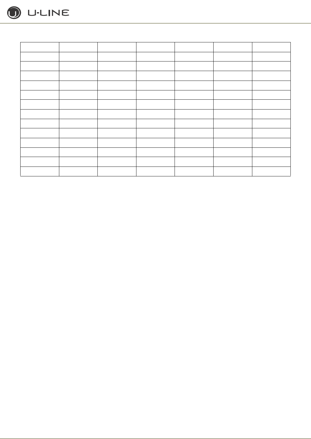
3-35
Section 3 - Service and Repair
Model Thermistor 1 Thermistor 2 Thermistor 3 Thermistor 4 Door Switch 1 Door Switch 2
2175R REF EVAP N/A N/A Yes N/A
2115R REF EVAP N/A N/A Yes N/A
2175WC REF EVAP N/A N/A Yes N/A
2115WC REF EVAP N/A N/A Yes N/A
2175DWRR REF EVAP Ambient N/A Bottom Drawer Top Drawer
CO2175F REF IM FZR Drain Pan Yes N/A
2175RF REF N/A FZR Drain Pan Yes N/A
CO2175DWR REF IM FZR Drain Pan Bottom Drawer Top Drawer
CLR2160 N/A IB N/A CON N/A P60
CLRCO2175 REF IB EVAP CON Yes P60
2175BEV REF EVAP N/A N/A Yes N/A
2275DWRWS Top Bottom Top Evap Bottom Evap Bottom Drawer Top Drawer
2275ZWC Top Bottom Top Evap Bottom Evap Yes N/A
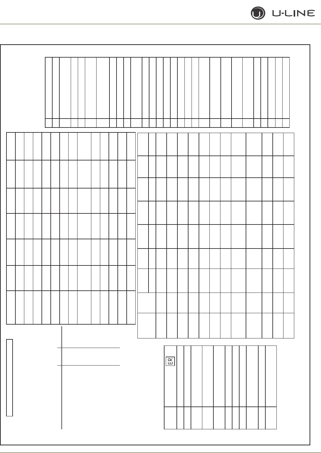
3-36
Section 3 - Service and Repair
Échelon Service Quick Reference Card
Model Part
Number
PIN 7
C_FAN
PIN 6
LIGHTS PIN 5 PIN 4
H_H20
PIN 3
C_PUMP
PIN 2
R_VALVE
PIN 7
BP_VALVE
Relay 1 Relay 2 Relay 3 Relay 4 Relay 5 Relay 6 Relay 7
2175R 61/75 Light Compressor/
Fan
2115R 71/73 Light Compressor/
Fan
2115WC 72/74 Light Compressor/
Fan
2175DWRR 70 Light 1 Compressor/
Fan Pan Heat Mull Heat
CO2175F 64/78 Cond Fan
E FAN Light Compressor Hot Gas
Valve
DRAIN
HEAT IM 1 IM2
2175RF 65/79 Cond Fan
E FAN Light Compressor Hot Gas
Valve
DRAIN
HEAT
CO2175DWR 66/80 Cond Fan
E FAN Light Compressor Hot Gas
Valve MULL HEAT IM 1 IM 2
CLR2160 67/81 Cond Fan Compressor
Hot Gas
Valve/Water
Valve
Circulation
Pump
CLRCO2175 68/82 Cond Fan Light Compressor
Hot Gas
Valve/Water
Valve
Ref Valve Ref Bypass
Valve
2175BEV 63177 Light Compressor/
Fan
2275DWRWS 85186 Cond Fan Bottom
Light Compressor Top Light Bottom
Valve To p Val ve
2275ZWC 87/88 Cond Fan Bottom
Light Compressor Top Light Bottom
Valve To p Val ve
#Description
1Light all LED segments
2Thermistor #1 status
(temp, E1 or E2)
3Error Log
4Defrost info
5Compressor runtime
(based on last cycle)
6Defrost length
(adjustable - up to 99 minutes)
7Light switch status (0 or 1)
8Display toggle status (0 or 1)
9Restore factory defaults
10 Adjust thermistor #1 offset
(-10° to +10°)
11 Data download
12 Clear error log
13 Clear download memory
14 Model number display
15 Adjust thermistor #1 differential
16 Adjust thermistor #2 offset
17 Adjust thermistor #3 offset
18 Adjust thermistor #4 offset
19 View thermistor #2 status
(temp or E7)
20 View thermistor #3 status
(temp or E8)
21 View thermistor #4 status
(temp or E9)
22 Automatic toggle through relays
(switch on and off)
23 Defrost interval adjustment
(3 to 24 hours)
24 Adjust thermistor #2 setpoint
25 Adjust thermistor #3 setpoint
26 Adjust thermistor #4 setpoint
27 Display software version
99 Exit
• Service Menu Options
(hold up arrow & touch light 3
times to access service menu)
• Use warmer/colder to scroll
through options
• Touch light bulb to enter and
before exiting an option
Model Thermistor 1 Thermistor 2 Thermistor 3 Thermistor 4 Door Switch 1 Door Switch 2
2175R Ref Evap N/A N/A Yes N/A
2115R Ref Evap N/A N/A Yes N/A
2115WC Ref Evap N/A N/A Yes N/A
2175WC Ref Evap N/A N/A Yes N/A
2175/2275 DWRR Ref Evap Ambient N/A Bottom Drawer Top Drawer
CO2175F Ref IM Freezer Drain Pan Yes N/A
2175RF Ref N/A Freezer Drain Pan Yes N/A
CO2175
CO2275 DWR Ref IM Freezer Drain Pan Bottom Drawer Top Drawer
CLR2160 N/A Ice Bin N/A Condenser N/A P60
CLRCO2175 Ref Ice Bin Ref Evap Condenser Yes P60
2175 BEV Ref Evap N/A N/A Yes N/A
2275DWRWS Top Ref Bottom Ref Top Evap Bottom Evap Bottom Drawer Top Drawer
2275ZWC Top Ref Bottom Ref Top Evap Bottom Evap Yes N/A
Error Code
E1 Thermistor #1 open
E2 Thermistor #1 shorted
E3 Door or bottom drawer open longer
than 20 minutes
E5 Thermistor #1 out of range (+10˚)
for more than 12 hours
E6 Thermistor #1 out of range (-10˚)
for more than 12 hours
E7 Thermistor #2 open or shorted
E8 Thermistor #3 open or shorted
E9 Thermistor #4 open or shorted
E10 Top drawer open longer than
20 minutes
E11 EE Memory Error
P1 Pump circuit open due to high water
level in ice bin
Description
(alternates with
setpoint display)
How to program a new board
1. Unplug unit and install new board
2. Plug unit in
3. The display may show a SP or --, either is OK
4. Install a jumper on J3
5. Hold down warmer, colder and light button until display shows
model number and main board beeps
6. Use warmer/colder to select new model number
Model 120 Volts 220 Volts Board Part #
2175R 61 75 68072
2175WC 62 76 68072
2175BEV 63 77 68072
CO2175F 64 78 68072
2175RF 65 79 68072
CO2175DWR / CO2275DWR 66 80 68072
CLR2160 67 81 68072
CLRCO2175 68 82 68072
2175DWRR / 2275DWRR 70 84 68072
2115R 71 73 68072
2115WC 72 74 68072
2275DWRWS 85 86 68084
2275ZWC 87 88 68084
7. Press and release light key
8. Wait for display to stop flashing
9. Remove jumper from board
10. Unplug unit and wait 5 seconds
11. Plug unit back in
Wait for the display to show the set point
Echelon Model Selection
Pump
Circulation
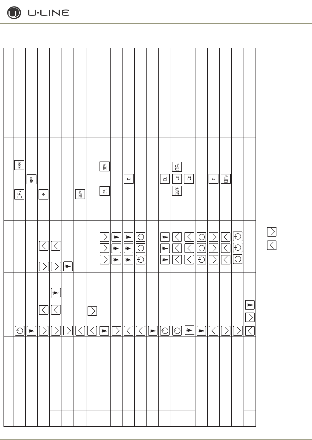
3-37
Section 3 - Service and Repair
Échelon Electronic Control Quick Reference Guide
Task Touch Touch Display Comments
1 On/Off Hold 10 Seconds Release when unit beeps or The CLR2160 will show
IC
E
2 Toggle Lights Glass door/drawer
models only
Light normally goes on/off with door opening. Pressing light
button will turn interior light on for 4 hours, then it will turn off.
3 Adjust Refrigerator Set-point or or Flashing Touch once to get into set mode,
then touch to adjust
42275DWRWC adjust lower drawer
set-point or or Bottom line of E flashes
Touch up/down once to get into set mode, touch light, for
bottom drawer then touch up/down to adjust
5 Adjust zone set-points 2278ZWC Touch to show zone Touch to set temp
Use warmer/colder to adjust temperature while small LED
is flashing
6 View actual temperature (T1)
Hold for
5 seconds
Flashing
WC’s will scroll top/middle/bottom temperatures
7 View actual temperature (T2 – T4) Scrolls through T2–T4 Flashing
8 Toggle F – C Hold or
9 Toggle Showroom Mode Hold Degree symbol flashes Repeat to exit mode
10 Service Mode Hold
See back of card for details
To exit, arrow up to 99 & touch light
11 Display Toggle
Glass door/drawer models only Hold Turns display on/off with door closed
12 Blackout Mode Hold for 10 seconds
Display (and cabinet light) not operable in
blackout mode
Hold light icon for 10 seconds to exit
13 Clean Cycle Hold
14 Icemaker Off Mode Hold Repeat to exit
15 Forced Harvest Hold Audible alert when entering this mode
16 Forced Refrigerator Defrost Hold Audible alert when entering this mode
17 Ice Thickness Adjustment Hold Use warmer/colder to adjust.
Touch light icon to exit.
18 Temporary Shutdown (Office Mode) Hold
Icemaker will automatically turn back on
in three hours
19 Relay Status Hold 21 30
Relay number with 1 or 0 to indicate on/off.
In this example relay 2 is on, relay 3 is off.
20 Change Mode Number (with jumper) Hold
2275ZWC use the left to enter or exit modes
Hold for 5 seconds
and
3-38
Section 3 - Service and Repair
ORIGINS ELECTRONIC CONTROL
Origins Keypad Options
DANGER
DANGER
Electrocution can cause death or serious injury. Burns from hot
or cold surfaces can cause serious injury. Take precautions when
servicing this unit.
• Disconnect the power source.
• Do not stand in standing water when working around
electrical appliances.
• Make sure the surfaces you touch are not hot or frozen.
• Do not touch a bare circuit board unless you are wearing
an anti-static wriststrap that is grounded to an electrical
ground or grounded water pipe.
• Handle circuit boards carefully and avoid touching
components.
NOTE: When touching key combinations in which you hold one key and
press another three times it is important to carefully follow the procedure.
1. Hold the desired key.
2. Press the other key three times.
3. Release the held key only after releasing the touched key for the
third time.
Except as noted, these functions are available on all models.
ON/OFF
The ON/OFF mode allows the unit to be turned on and off via the
keypad. To do this, hold the key for approximately 10 seconds until
the “F” begins to flash. Release and the unit will switch modes. In the
OFF position the cabinet light will remain operational. This mode
does not disconnect power from the circuit board so it is still “live.”
CABINET LIGHT
On units with glass doors, touching the LIGHT key will turn on the
cabinet light for four hours at a time. Touching the key again will turn
the light off. Using the cabinet light for more than four hours may be
detrimental to the cabinet temperature and product. Only available
on 1175BEV, 1115WC and 1175WC models.
IMPORTANT
IMPORTANT
This does not apply to ADA24R glass door units. The
light and display are always off when the glass door
is closed.
Adjusting the Set-point
To adjust the set-point press and release either the WARMER or
COLDER key. This will start the set-point flashing. While in this
mode you can adjust the set-point warmer or colder until the desired
temperature is reached. The factory recommended set-point is 38°F
for refrigerators/refrigerator-freezers and 50°F for wine coolers.
When adjustment is complete stop touching the display and the set-
point will be saved in approximately five seconds.
VIEWING ACTUAL TEMPERATURE
In viewing temperature in these modes any offsets are taken into
account. This means that if you place a thermistor in a known
temperature, let’s say ice water, it may not read the 32°F that you
would assume. If the control offset was preset at -3°F while you
placed the thermistor in an icebath, the actual thermistor reading
when viewing actual temperature would read 35°F. In the unit this
would cause the cabinet to push itself 3° cooler. To view pure
thermistor readings you must go into the service menu and choose
the correct option.
To view the thermistor temperature, hold the WARMER key for
approximately five seconds until the “F” flashes. Release and the
display will show the corrected refrigerator temperature. For Wine
Cooler models the display will cycle through all three zones. These
temperatures are approximate and calibrated for a cabinet in normal
ambient temperatures with some product load. Checking a
completely unloaded cabinet may result in other temperatures.
CHANGING FROM FAHRENHEIT TO CELSIUS
To change the displayed temperature from °F to °C, hold the LIGHT
key and press COLDER three times. This will change all values to °C.
When the key combination is accepted the control will change values.
SHOWROOM MODE
This mode is designed to show units in a display environment. When
in this mode the only functions will be the control and cabinet lights.
The compressor, fans, etc. will not operate. To enter this mode hold
the COLDER key and press the LIGHT button three times. Once
entered, the degree symbol will begin to flash. When the degree
symbol is flashing the unit will allow the use of the control for
demonstrations. After not touching the unit for one minute the
display will begin to “snake” around. This is meant to alert you the
unit is in showroom mode. The unit can be left in this mode
indefinitely. If you again want to demo the control, touch any key and
the degree symbol will begin to flash. To exit this mode: This mode
needs to be exited by the same key combination as used to enter the
mode.
SERVICE MODE
This mode has 16 different options available for service diagnostics.
To enter the mode hold the WARMER key and press the LIGHT
button three times. The display will show “0.” When in this mode the
WARMER and COLDER keys will act as up and down arrows to
select the desired option. The LIGHT key is the ENTER key and will
enter a function. If changing a setting, you must press the LIGHT key
again to retain the changed setting. To exit the service mode scroll to
option 99 and press the LIGHT key. After five minutes of not
touching any keys the mode will also exit automatically.
DISPLAY TOGGLE
On glass door units the display normally stays on all the time. To have
the display go off with the door, press the up arrow and touch the
ON/OFF key three times. The °F sign will flash to let you know the
mode has been accepted. This mode can be toggled on or off by the
same key combination. To see if the display should be staying on 100%
or turning off with the door, you can check service option 8. Only
available on 1115WC and 1175WC.
BLACKOUT MODE
Hold the LIGHT key for 10 seconds until the °F starts flashing. When
released, the unit will beep once and the display and cabinet light will
shut off. It will stay off for 36 hours, at which time it will automatically

3-39
Section 3 - Service and Repair
turn back on. If desired, you can manually cancel this mode by
touching the LIGHT button. Release and the unit will automatically
start normal operation.
MODEL NUMBER CHANGE
Origins Model Selection:
Origins Service Menu
Enter service menu by holding WARMER and pressing LIGHT
three times. Select option 1 to 16 with the WARMER and
COLDER keys. To enter the option, press the LIGHT key. If
changing a setting, you must press the LIGHT key again to retain
the changed setting.
When entering service mode all other modes are cancelled and
the unit will stop operating. When exiting service mode the unit
will begin to operate normally, however the four-minute
compressor off cycle still applies.
1. Light all LED segments
This will illuminate all the LEDs on the board to ensure they
work properly.
2. Thermistor 1 status—Temperature, E1, or E2
This will show the pure thermistor reading with no offsets
taken into account. When placed in ice water this thermistor
should read 32°F in this menu option.
3. Error log
A list of the errors in the order they occurred will scroll once
on the display. Repeat if desired. Once viewed perform option
12 to clear the errors from memory.
4. Defrost information
Displays the number of defrosts that have occurred in the past
24 hours.
5. Compressor runtime based on last cycle
This will show the number of minutes the compressor has run
in the prior cycle (or current cycle if the compressor was
running when service mode was entered).
6. Defrost length adjust min—99 minutes
The length of the defrost can be adjusted up to 99 minutes
long (for every six hours). The other defrost parameters still
apply. Lengthening a defrost may cause higher than normal
temperatures in the refrigerator section.
7. Light switch 1 status—0 or 1
This will tell if the light should turn off with the door switch or
not. At the “0” reading the light should be off with the door
closed and on with the door open. At the “1” reading the light
stays on always.
8. Display toggle status—0 or 1
This will tell if the display should turn off with the door switch
or not. At the “0” reading the light should be off with the door
closed and on with the door open. At the “1” reading the light
stays on always.
9. Restore factory defaults
This will restore the default set-point, defrost and offset values.
10. Adjust thermistor 1 offset—10 to +10F
This allows calibration of the sensor to cabinet for abnormal
operations. By adjusting this number colder you can change the
average cabinet temperature to a colder value.
11. Data download
Along with the separate USPY software you can download the
rolling data file.
12. Clear error log
Perform this operation after checking the errors.
13. Clear download memory
Clears the rolling data file if desired.
14. Model number displayed
Displays the two-digit model number of the specific unit.
15. Adjust thermistor 1 differential.
This number should not be adjusted.
16. Software number
This will show the software on the board.
1. Make sure board is not plugged in.
2. Hold down ON/OFF key and plug in unit.
3. Release ON/OFF key.
4. Press and release LIGHT icon.
5. Use WARMER/COLDER to select the model
number desired.
49-1175R/ADA24R 120V
50-1175WC 120V
51-1175BEV 120V
52-1175R 220V
53-1175WC 220V
54-1175BEV 220V
56-1115R 120V
57-1115R 220V
77-1115WC 120V
78-1115WC 220V
6. Press and release LIGHT icon.
7. Wait for display to stop.
8. Unplug unit and wait 5 seconds.
9. Plug unit back in.
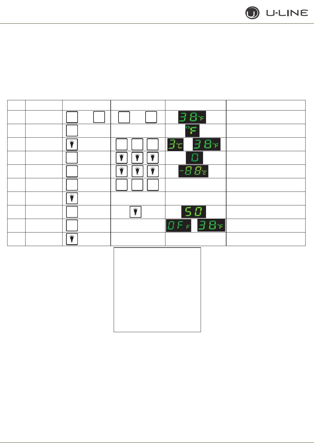
3-40
Section 3 - Service and Repair
Error Codes
E1 Thermistor 1 is open.
E2 Thermistor 1 is shorted.
E3 Main door or bottom drawer is open longer than 20 minutes.
E4 Compressor had 100% runtime between two defrost cycles.
E5 Thermistor 1 out of range + 10°F for more than 12 hours.
E6 Thermistor 1 out of range -10°F for more than 12 hours.
All errors show up on display alternating between SP and
the actual code.
Origins Electronic Control Quick Reference Guide
k s a T h c
u o T h c u o
T y
a l p s i
D t n e m m o C
t n i o p t e S t
s u
j d A r o r
o o t h c u o t n e h t , e d o m t e s
o t n i t e g o t e c n
o h c u o T
t s u j d a
p m e T
l a u
t c A
w e
i V s d n o
c e s 5 d l
o
H . s e r u t a r e p m
e t t o B / d i M /
p o
T l l o r c s l l i w C W
C / F e g n a h C 1 d l o H r o
e d o M
e
c i v
r e S 2 d
l o H r e d l o c
r o
r
e m r a w
e s U . s e t
u n i m
5 r e t
f
a t u o s e m i T
. w
e
i v o t n o t t u b t h g
i
l , l l o r c s
o t
3 e d
o M
m o
o
R
w o h S
e l g g o T d l o H
y a l p s i d
n
e h
t , t
s
r i
f
t
a s e h s a l
f
l
o
b m y
s
e
e
r g e D
. y t i v i t c a
n i
f
o e t u n i m e n o r e t f a
S
D
E
L
l l
a
s e k
a
n s
. e v o m e
r
o
t
n o i t a n i b m o
c
y e k
e m
a S
e
l
g
g
o T
y
a
l p s
i D 4 .
d e
s o
l
c s
i
r o o d
e l
i h
w S D
E
L l o
r
t n o c
y a
l p
s
i
D
) y l n O s l e d o M r o o D s s a l G (
e d o M t u o k c
a
l B
5 s d
n
o
c e
s
0
1
d
l
o
H e r
o
t s e r
o t
n o
t
t u b
t h g i l e s
u
r
o s r u
o h
6 3
f f
o
s
y
a t S
y a l p s i d d n a s t h g i l
l
e
d
o M e g n a
h
C 6
e l i h w d
l
o
H
n i g
n
i g g
u l
p
F F O
/
N O n r u T 7 s d
n o
c e
s
0 1 d l o H or o
t h g i
L
t e
n
i
b
a
C 8 e s
a e l
e R & h c u o T
.
g
n i
n e p o r
o
o d
h
t i w f f o / n o
s
e
o g y l l a m
r
o n t h
g
i L
r o
f n o
t h g i l r
o i
r e
t n
i
n
r u t
l l i
w n
o t
t
u b t h
g
i l
g
n i
s s e
r P
.
f f o n
r u
t
l l
i
w
t i
n e h
t
s r u o
h
4
g n i t s i L
e d o M e c i
v
r e S se d o
C
r o r r E
s t n e m g e s D E L l l a t h g i L 1 0 n e p o r o t s i m r e h T - 1 E
s u t a t S r o t s
i
m r
e
h T 2 0 d
e
t
r
o h s r o t
s
i m r
e
h
T
- 2 E
g o L r o
r
r E 3 0 s
e
t
u
n
i m 0 2 n a h t r e
g
n o l n e p o r o
o
D
-
3
E
) s r u o h 4 2 t
s
a p
n
i
#
(
o
f n
I
t
s o r f e D 4 0 n u r % 0 0 1 h t i w s l a v r e t n i t s o r f e d f
o
#
- 4 E
e l
c y
c t s a
l
e
c n i
s e
m i
t
n
o
p
m
o C 5
0 t n
i o
p
t e s
r e v
o
s
e e
r
g
e
d
0 1
p m
e
t
l a u t c A
-
5 E
h t g
n
e
L
t s
o r
f e
D
6 0 s
r u
o
h
6 n
a
h t
e r o
m
r o f
n o - 1
r o o
d
/
w
e l
g g
o t - 0 (
s u
t a t S h
c
t i w S
t
h
g i L 7 0 )
s y
a
w l
a
t
n
i o
p
t e s r e d
n u
s e e r g e
d
0 1 p m
e t
l a u t
c A -
6
E
w
l a
n o
- 1
r o
o d
/
w
e
l g g
o t
- 0 (
s u
t
a
t S
y a
l p s i D
8 0 )
s
y a s
r
u o h
6
n a h
t
e
r
o m r
o
f
) s g
o l
s e d
u l
c n
i (
s
t
l u a f e D e
r
o t
s
e
R
9
0
t e
s
f f O
t
s
u j
d A 0 1
d a o l n w o D a t a D 1 1
g o
L
r
o r
r E
r a e l C
2 1
y r o m e M
d
a o l n
w
o D
r a e l C
3
1
r
e b
m u
N l e d
o M y a l
p s
i
D
4 1
)
y e k
f f o / n o &
t
h
g i l e
s
u
(
l a i t n e r e f
f
i D t
s
u j d A 5 1
n
o i s r e v
e
r a w t
f
o S
y a l p
s i D
6
1
e d o M e c i
v
r
e
S t i x E
9
9
:n
o
i
t
c
e l
e
S
l e
d
o M
s n
i
g
i r O
e unit is not plugged in.
r u
s e
k a
M .
1
. t i n
u
n
i
g u l p
d n
a
y
e k
f f
o / n o n
w o
d
d
l o
H
. 2
.
y e
k f f o / n o
e
s
a e l
e R
.
3
. y e k t h g i l
e s a e
l
e
r
d n
a
s
s
e r P
. 4
e d o m e
h
t t c e
l
e
s
o t
r
e d l o c
/
r e m
r
a w
e
s U . 5
r
e b m u n l
.
d
e r i
s
e d
V 0
2
1
R 5
7 1 1
- 9
4
.
a
V 0 2 1
C
W 5 7 1 1
- 0
5
.
b
V 0 2 1
V E B 5 7 1 1 - 1
5
.
c
V 0 2
2
R 5 7 1
1 -
2
5
.
d
V 0 2 2
C
W 5 7 1 1
- 3
5
.
e
V 0
2 2
V E B 5
7 1
1
- 4 5
.
f
V 0
2
1
R 5 1 1 1 - 6
5
.
g
V 0
2
2
R 5
1 1
1 - 7 5
. h
V 0 2 1 C
W
5
1 1
1
- 7 7
.
i
V
0 2
2
C
W
5
1 1
1
- 8 7
. j
. y e k
t
h g i l e s
a e
l e r d n
a
s s e r P . 6
.
p
o t
s
o
t g n i h s a l f
r
o f t
i
a W
. 7
. s d n o
c e s
5
t i
a
w
- t i
n u
g
u
l
p n U . 8
. 9
. n i
k
c a b
t i n u g u l P
R
E M R
A
W R
E
L
O
O C
R E M R A W
R
E
M R
A
W
R
E M
R A W
R
E M
R A W
R
E L O O
C
R
E L O O
C R
E L O O
C R
E L O O
C
R
E L O O
C
/ N O
F F O
/ N O
F F O
/ N O
F F
O
/ N O
F
F O
/ N O
F F
O
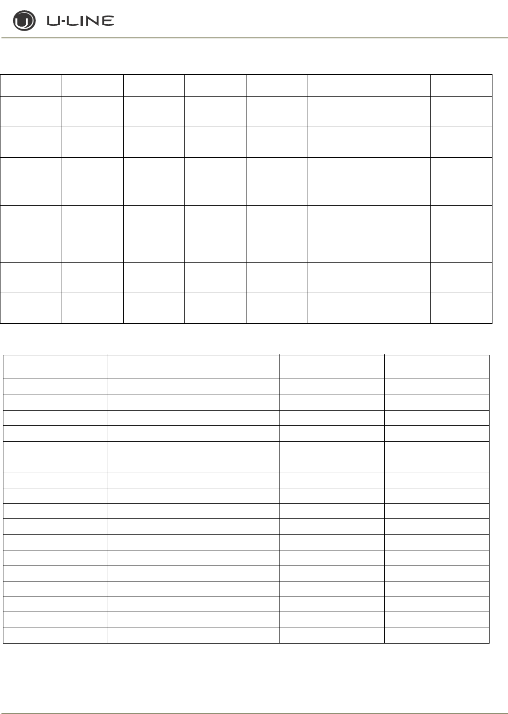
3-41
Section 3 - Service and Repair
Refrigeration System Diagnosis Guide
DEFROST INFORMATION - ALL MODELS
System
Condition
Suction
Pressure
Suction
Line
Compressor
Discharge
Condenser Capillary
Tube
Evaporator Wattage
Normal Normal Slightly below
room
temperature
Very hot Very hot Warm Cold Normal
Overcharge Higher than
normal
Very cold -
may frost
heavily
Slightly warm
to hot
Hot to warm Cool Cold Higher than
normal
Undercharge Lower than
normal
Warm -
near room
temperature
Hot Warm Warm Extremely cold
near inlet -
outlet below
room
temperature
Lower than
normal
Partial
Restriction
Somewhat
lower than
normal -
in vacuum
Warm -
near room
temperature
Very hot Top passes
warm -
lower passes
cool (near room
temperature
due to liquid
Room
temperature
(cool) or colder
Extremely cold
near inlet -
outlet below
room
temperature
backing up
Lower than
normal
Complete
Restriction
In deep
vacuum
Room
temperature
(cool)
Room
temperature
(cool)
Room
temperature
(cool)
Room
temperature
(cool)
No
refrigeration
Lower than
normal
No Gas 0 PSIG
to 25"
Room
temperature
(cool)
Cool to hot Room
temperature
(cool)
Room
temperature
(cool)
No
refrigeration
Lower than
normal
Model Hours Between Defrost Time
(Runtime) (Adjustable) Length/min Stop Point
2175R 6 90 42°
2115R 6 90 42°
2175WC 6 90 45°
2115WC 6 90 45°
2175BEV 6 90 42°
2175/2275DWRR 6 90 42°
CO2175F 12 18*/45 42°
2175RF 12 18*/45 42°
CO21752275DWR 12 18*/45 42°
CLRCO2175 6 90 42°
2275DWRWS 12 90 45° (both drawers)
2275ZWCS/2275ZWCOL 12 75 45° (both zones)
1115R 4 60 -
1175R/ADA24R 6 45 -
1115WC 6 45 -
1175WC 6 45 -
1175BEV 6 45 -
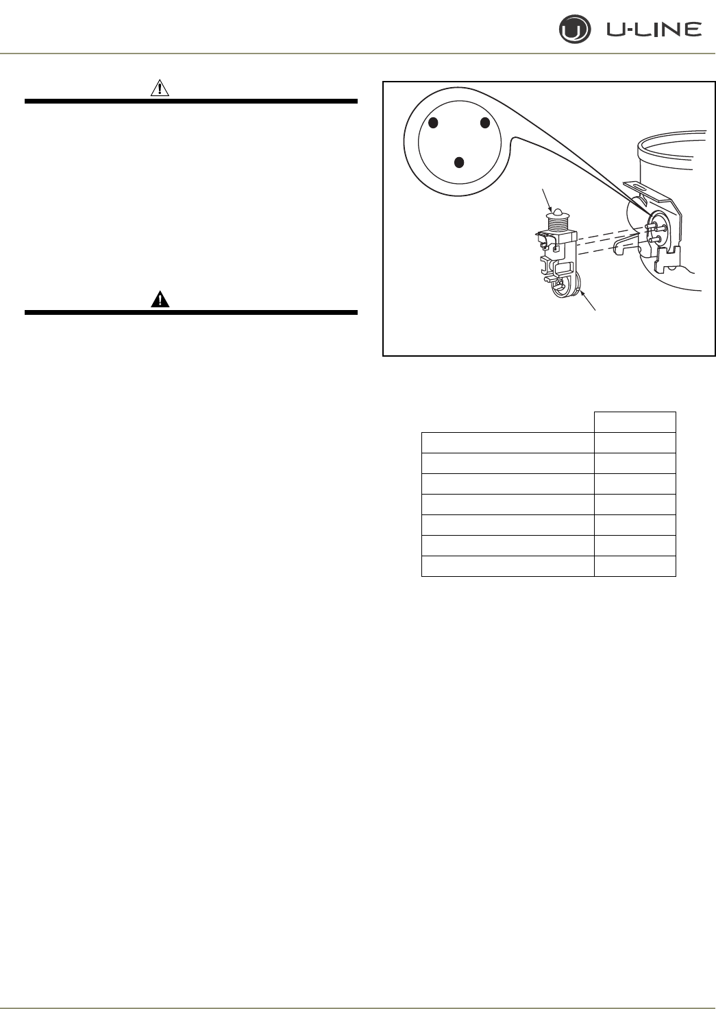
3-42
Section 3 - Service and Repair
CAUTION
If frost is heavy, divert water from drain to prevent water
from overflowing on the floor.
SPECIFICATIONS
CLR2160
COMPRESSOR/COIL SPECIFICATIONS
DANGERDANGER
Electrocution can cause death or serious injury. Burns from
hot or cold surfaces can cause serious injury. Take precautions
when servicing this unit.
• Disconnect the power source.
• Do not stand in standing water when working around
electrical appliances.
• Make sure the surfaces you touch are not hot or
frozen.
• Do not touch a bare circuit board unless you are
wearing an anti-static wriststrap that is grounded to
an electrical ground or grounded water pipe.
• Handle circuit boards carefully and avoid touching
components.
To measure the start winding resistance measure across the C and
S pins.
To measure the run winding resistance measure across the C and R
pins.
Also check S to R and you should get the sum of the run and start
windings.
To ensure the windings are not shorted check the S and R to
ground.
Figure 26. CLR2160
Water Valve 275 Ohms
Bypass Coil 300 Ohms
Pump Motor 72 Ohms
THERMISTORS
The U-Line Model CLR2160 uses two thermistors. The
thermistors are used in conjunction with the control panel to
monitor the unit’s functions and troubleshooting capabilities. A
type 1 thermistor is attached to the condenser dryer inlet and
senses temperature after the condenser to signal length of ice-
making and harvesting time. A type 2 thermistor senses the ice
level in the ice bin and maintains ice level in the bin.
REED SWITCH
None on this model.
EMY70HER
Voltage 115-127
Frequency 60.0
LRA 26.5
FLA 2.7
Start Winding 8.1
Run Winding 3.2
Capacitor N/A
C
S
R
ULIN_0568_A
STARTING
RELAY
3/4" OVERLOAD
PROTECTION
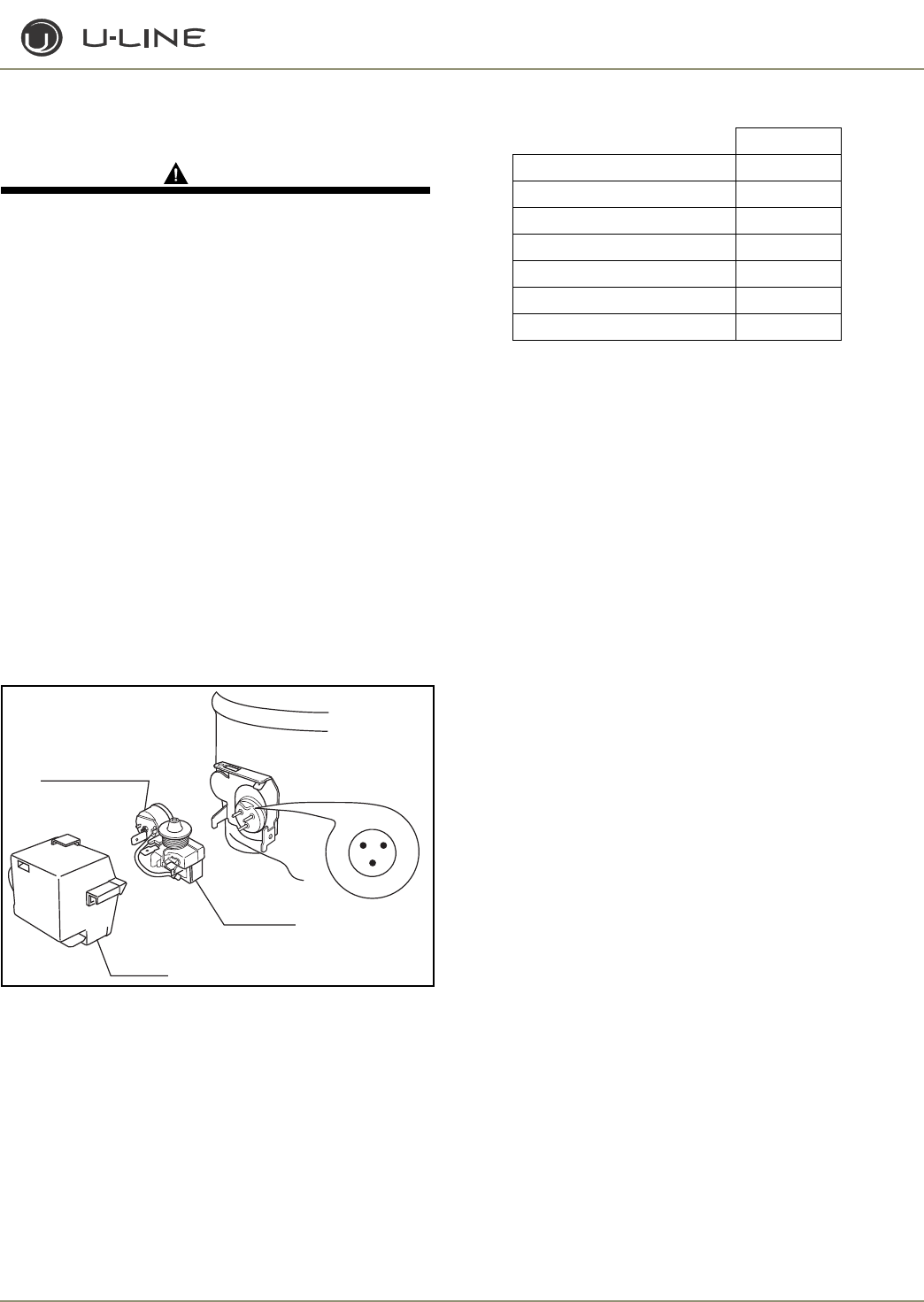
3-43
Section 3 - Service and Repair
CLRCO2175
COMPRESSOR/COIL SPECIFICATIONS
DANGERDANGER
Electrocution can cause death or serious injury. Burns from
hot or cold surfaces can cause serious injury. Take precautions
when servicing this unit.
• Disconnect the power source.
• Do not stand in standing water when working around
electrical appliances.
• Make sure the surfaces you touch are not hot or
frozen.
• Do not touch a bare circuit board unless you are
wearing an anti-static wriststrap that is grounded to
an electrical ground or grounded water pipe.
• Handle circuit boards carefully and avoid touching
components.
To measure the start winding resistance, measure across the C and
S pins.
To measure the run winding resistance, measure across the C and
R pins.
Also check S to R and you should get the sum of the run and start
windings.
To ensure the windings are not shorted, check the S and R to
ground.
Figure 27. CLRCO2175
Water Valve 275 Ohms
Bypass Coil 300 Ohms
Pump Motor 72 Ohms
Refrigeration coils 150 Ohms
THERMISTORS
Four thermistors are employed. A type 1 thermistor is used to
measure the condenser temperature and determine the freeze and
harvest cycles in conjunction with the custom electronic board. A
type 2 thermistor is used to measure the ice bin, refrigerator, and
evaporator temperatures.
REED SWITCH
A reed switch is mounted to the underside of the cabinet and a
magnet is mounted to the door. When the door is closed the
magnet trips the switch which turns the light and display off. This
also sets an audible warning.
DEFROST
For the refrigerator defrost information, please refer to page 3-40.
ULIN_0576_AW
R S
C
OVERLOAD PROTECTOR
STARTING RELAY
RELAY COVER
FF7.5HBK
Voltage 115.0
Frequency 60.0
LRA 25.5
FLA 4.0
Start Winding 11.2
Run Winding 2.2
Capacitor N/A
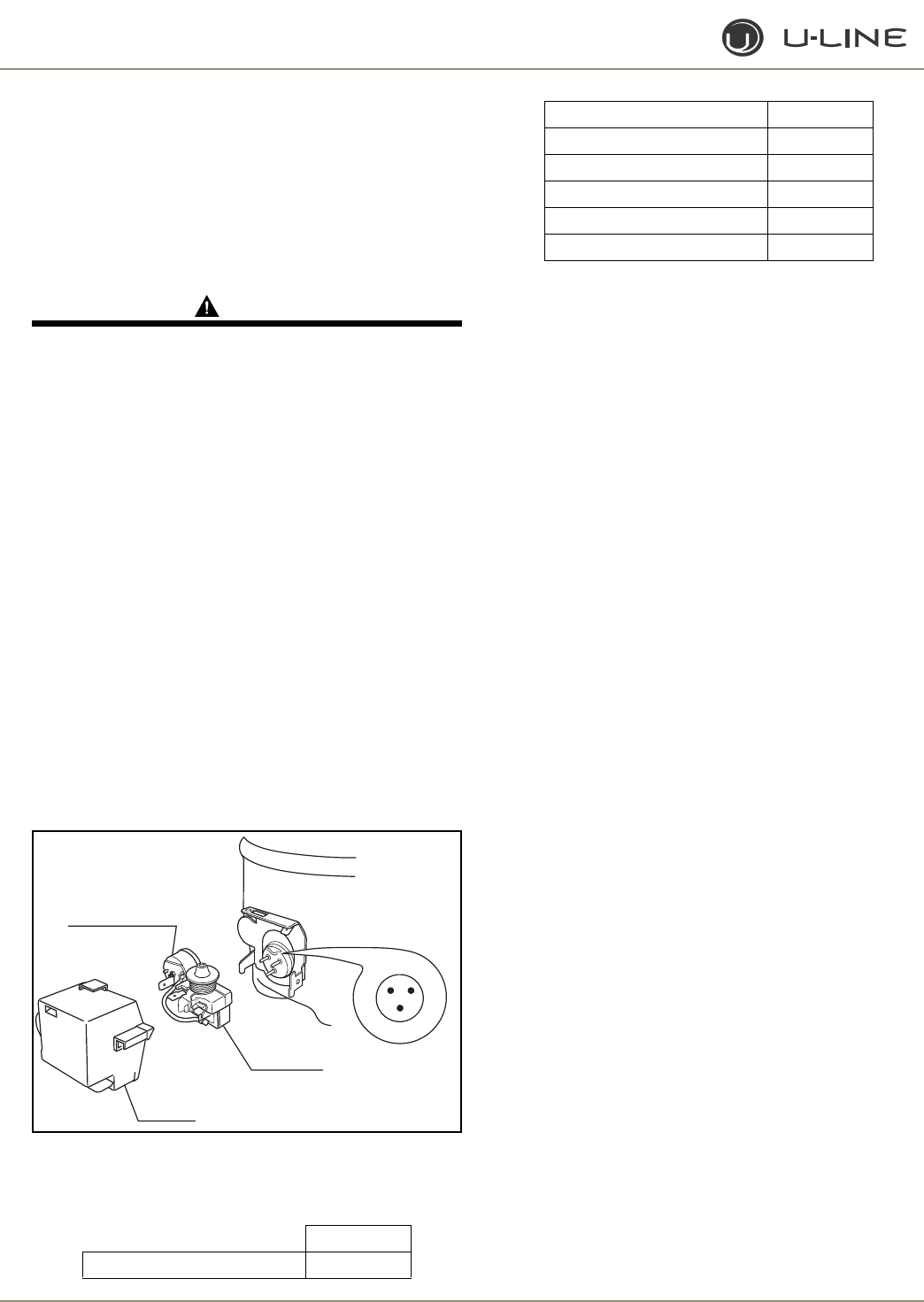
3-44
Section 3 - Service and Repair
2175R/2115R
2175WC/2115WC
2175BEV
2175DWRR/2275DWRR
2275DWRWS/2275ZWC
COMPRESSOR/COIL SPECIFICATIONS
DANGERDANGER
Electrocution can cause death or serious injury. Burns from
hot or cold surfaces can cause serious injury. Take precautions
when servicing this unit.
• Disconnect the power source.
• Do not stand in standing water when working around
electrical appliances.
• Make sure the surfaces you touch are not hot or
frozen.
• Do not touch a bare circuit board unless you are
wearing an anti-static wriststrap that is grounded to
an electrical ground or grounded water pipe.
• Handle circuit boards carefully and avoid touching
components.
To measure the start winding resistance, measure across the C and
S pins.
To measure the run winding resistance, measure across the C and
R pins.
Also check S to R and you should get the sum of the run and start
windings.
To ensure the windings are not shorted, check the S and R to
ground.
Figure 28. 2175R/2115R/2175WC/2115WC/2175BEV/
2175WRR/2175DWRWS
REFRIGERATOR COIL OHMS-2175DWRWS/2275ZWC
Refrigeration coils 3000 Ohms
THERMISTORS
Two or four thermistors are employed. A type 2 thermistor is used
to measure the refrigerator and evaporator temperatures.
REED SWITCH
A reed switch is mounted to the underside of the cabinet and a
magnet is mounted to the door. When the door is closed the
magnet trips the switch which turns the light and display off. This
also sets an audible warning.
DEFROST
For the refrigerator defrost information, please refer to the 2175R
model on page 32.
EMY70HER
Voltage 115-127
ULIN_0576_AW
R S
C
OVERLOAD PROTECTOR
STARTING RELAY
RELAY COVER
Frequency 60.0
LRA 26.5
FLA 2.7
Start Winding 8.1
Run Winding 3.2
Capacitor N/A
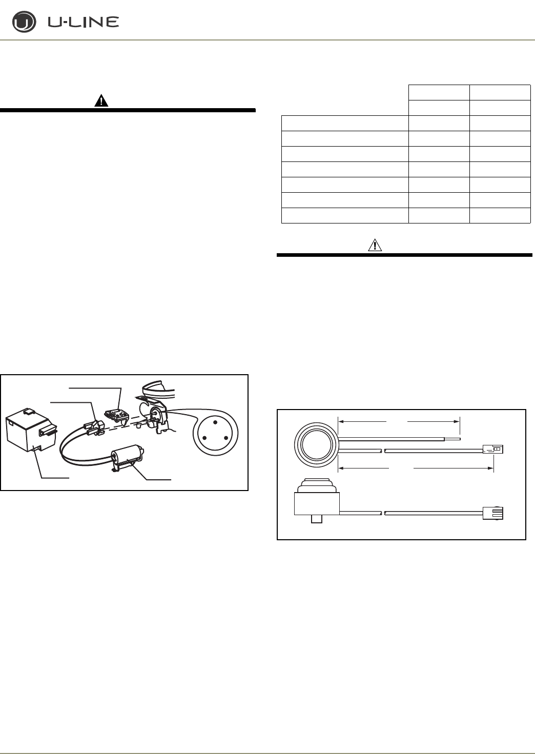
3-45
Section 3 - Service and Repair
CO2175F/2175RF/CO2175DWR
COMPRESSOR/COIL SPECIFICATIONS
DANGER
DANGER
Electrocution can cause death or serious injury. Burns from hot
or cold surfaces can cause serious injury. Take precautions when
servicing this unit.
• Disconnect the power source.
• Do not stand in standing water when working around
electrical appliances.
• Make sure the surfaces you touch are not hot or frozen.
• Do not touch a bare circuit board unless you are
wearing an anti-static wriststrap that is grounded to an
electrical ground or grounded water pipe.
• Handle circuit boards carefully and avoid touching
components.
To measure the start winding resistance, measure across the C and S
pins.
To measure the run winding resistance, measure across the C and R
pins.
Also check S to R and you should get the sum of the run and start
windings.
To ensure the windings are not shorted, check the S and R to ground
Figure 29. CO2175F/2175RF/CO2175DWR
WARNING
Do not cycle ice maker by hand. This will cause damage
to the ice maker.
Part Resistance
Ice Maker Heater-110V 80
Ice Maker Heater-220V 320
Mullion Heater 1600
Pan Heater 6350
Bypass coil 300
120V water valve 335
220V water valve 1900
ICE MAKER LIMIT SWITCH
Figure 30. Ice Maker Limit Switch-Normally Closed
C
SR
OVERLOAD PROTECTOR
STARTING RELAY
CAPACITOR
RELAY COVER
ULIN_0368_A
EMU45HSC EMY70HER
5408 70081
Voltage 115.0 115-127
Frequency 60.0 60.0
LRA 6.5 26.5
FLA 1.5 2.7
Start Winding 5.6 8.1
Run Winding 6.7 3.2
Capacitor 15uF N/A
3.00
28.12
ULIN-0351_A
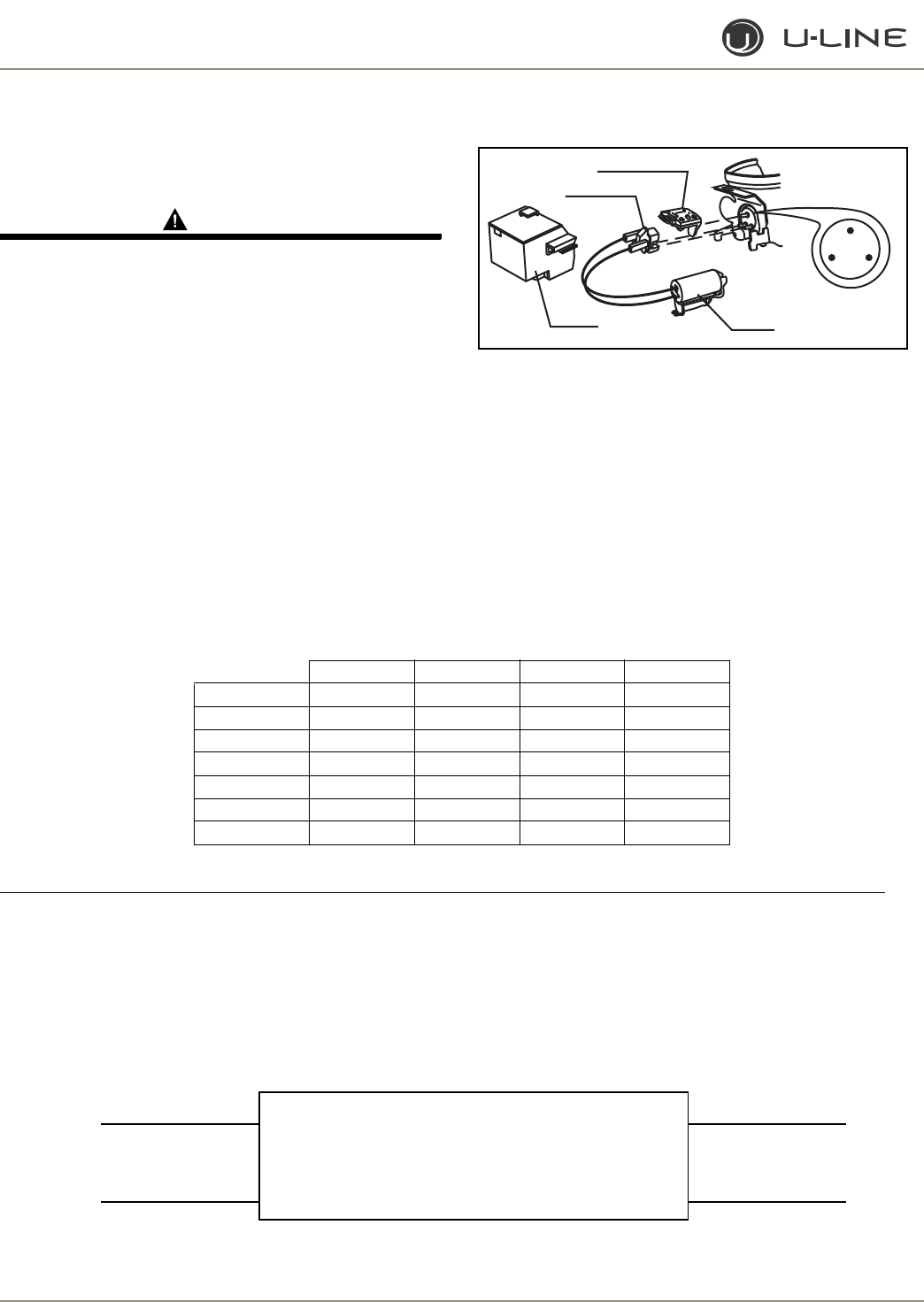
3-46
Section 3 - Service and Repair
1175R/1115R
1175WC/1115WC
1175BEV/ADA24R
COMPRESSOR/COIL SPECIFICATIONS
DANGER
DANGER
Electrocution can cause death or serious injury. Burns from hot
or cold surfaces can cause serious injury. Take precautions when
servicing this unit.
• Disconnect the power source.
• Do not stand in standing water when working around
electrical appliances.
• Make sure the surfaces you touch are not hot or frozen.
• Do not touch a bare circuit board unless you are
wearing an anti-static wriststrap that is grounded to an
electrical ground or grounded water pipe.
• Handle circuit boards carefully and avoid touching
components.
To measure the start winding resistance, measure across the C and S
pins.
To measure the run winding resistance, measure across the C and R
pins.
Also check S to R and you should get the sum of the run and start
windings.
To ensure the windings are not shorted, check the S and R to ground.
Figure 31. 1175R/1115R/1175WC/1115WC/1175BEV
THERMISTORS
For all models, one type 2 thermistor is mounted to the sidewall.
Reed Switch
A reed switch is mounted to the underside of the cabinet and a
magnet is mounted to the door. When the door is closed, the magnet
trips the switch which turns the light and display off. For glass door
models the display remains on unless toggled.
IMPORTANT
The U-Line ADA24R models employ both a 12VDC evaporator fan assembly and condenser fan assembly. The
motors are powered by a 12VDC power supply located in the base of the unit. These fans are designed to
operate in conjunction with the compressor and should be running whenever power is applied to the
compressor electricals. These motors do not require external lubrication and do not overtighten the mounting
screws upon installation (tab breakage could occur).
C
SR
OVERLOAD PROTECTOR
STARTING RELAY
CAPACITOR
RELAY COVER
ULIN_0368_A
5400 5403 70075 70077
Voltage 115.0 220-240 115.0 115.0
Frequency 60.0 50.0 60.0 60.0
LRA 9.8 4.0 6.0 5.5
FLA 1.2 0.7 1.2 1.0
Start Winding 21.2 39.5 4.2 7.0
Run Winding 7.9 28.6 5.4 8.4
Capacitor N/A N/A opt 15 uF 12uF
BLUE (NEUTRAL) RED + (POSITIVE)
Input Output
BROWN (HOT/LIVE BLACK - (NEGATIVE)
U-Line Part # 68103
Transformer/Power Supply
100-240VAC (0.55AMP MAX)
12VDC (1.7 AMP MAX)
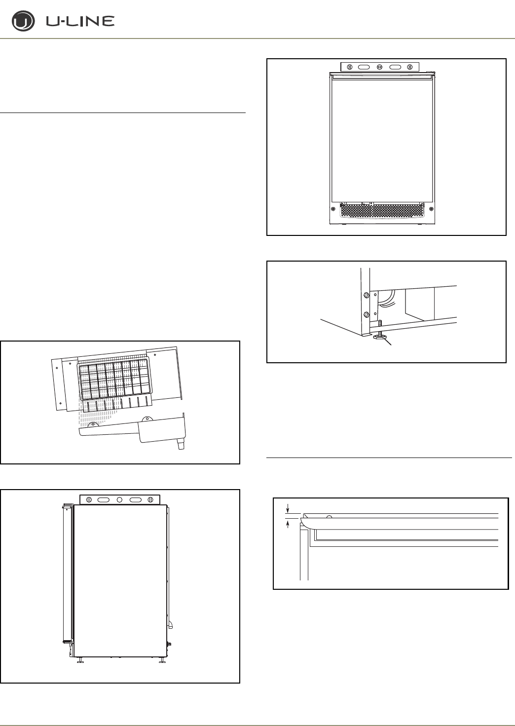
3-47
Section 3 - Service and Repair
ADJUSTMENTS AND REPAIR
Leveling
IMPORTANT
IMPORTANT
It is extremely important that the unit is level for maximum
production.
If it is not:
Doors or drawers will not work properly.
In ice maker units, uneven sized cubes will be formed. Ice
production will reduce and water spilling into the storage
area can occur causing the ice in the bin to melt
prematurely (Figure 32).
Remember, floors surrounding a drain have a tendency to
slope toward the drain.
1. Use a level to check the unit from front to back (Figure 33) and
from side to side (Figure 34).
2. If the unit is not level, adjust the feet on the corners as necessary
(Figure 35)
. Rotating the feet clockwise raises the unit.
Check after each adjustment and repeat the previous steps as
necessary until the unit is level.
Figure 32
Figure 33
Figure 34
Figure 35
Door Alignment - Échelon Models
The unit’s door is aligned at the factory before shipment. However,
its alignment could have been disturbed during shipment or during
door panel installation.
IMPORTANT
IMPORTANT
Properly aligned, the door should be 1/8" below the top of
the unit’s cabinet, NOT flush with the top (Figure 36).
Figure 36
1. Compare the top edge of the door to the top edge of the cabinet.
2. If the door edge is 1/8" below and parallel to the top of the cabinet,
it is adjusted correctly. If it is not, note whether the side opposite
the hinge needs to be moved UP or DOWN, and use the following
procedure.
ÉCHELON FULL OVERLAY
ULIN_0047_A
ULIN_0367_A
SIDE
FRONT
1ULIN_0044_A
1/8"
ULIN_0295_A
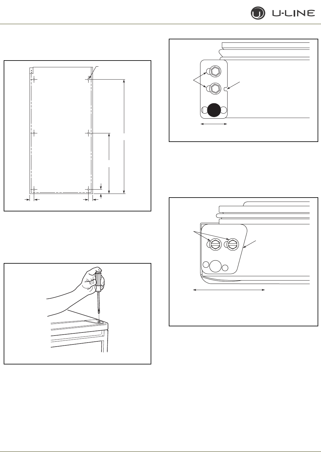
3-48
Section 3 - Service and Repair
NOTE: If door is adjusted correctly, but panel is not square with the
adjacent cabinets, slight adjustments can be made by drilling the holes
in the vinyl-coated steel panel slightly oversized (Figure 37).
Figure 37
ADJUSTING DOOR ALIGNMENT
1. Remove top hinge screw pin using a Phillips screwdriver (Figure
38). Remove door by tilting forward and lifting off bottom hinge
pin.
Figure 38
2. With door upside-down, loosen but do not remove the two
screws on the door’s bottom hinge plate.
Figure 39
3. See
Figure 39
and
Figure 40
. If the top far edge of the door
needs to move UP, move the hinge plate toward the outside of the
door and retighten screws. If the top far edge of the door needs to
move DOWN, move the hinge plate toward the inside of the door
and retighten screws.
Figure 40
4. Mount the door to recheck alignment and repeat steps 2 and 3 if
further adjustment is necessary.
5. When top edge of door is parallel to top edge of cabinet, remove
the door and ensure the two screws are secure.
6. Remove the door closers from the bottom hinge, clean thoroughly
and lubricate the mating surfaces with petroleum jelly.
7. Reinstall the closers, lining up the bosses with holes in hinge and
hinge plate
(Figure 41)
.
Drill 5/32" x 3/8" Deep for use
with #10 x 5/8" Wood Screw
and Nylon Spacer –
6 Places
1"±1/8"
1"±1/32"1"±1/32"
14-5/16"±1/4"
27"±1/4"
Rear View
of
Wood Panel
ULIN_0310_A
ULIN_0133_A
Notch must face center of door
Slotted
Mounting
Holes
Raise
Outside
Door Edge
Lower
Outside
Door Edge ULIN_0297_A
Angled Edge
Towards Center
of Door
Slotted
Mounting
Holes
Raise
Outside
Door Edge
Lower
Outside
Door Edge
ULIN_0311_A
2115WC, 2115WCOL, 2175WC, 2175WCOL Only
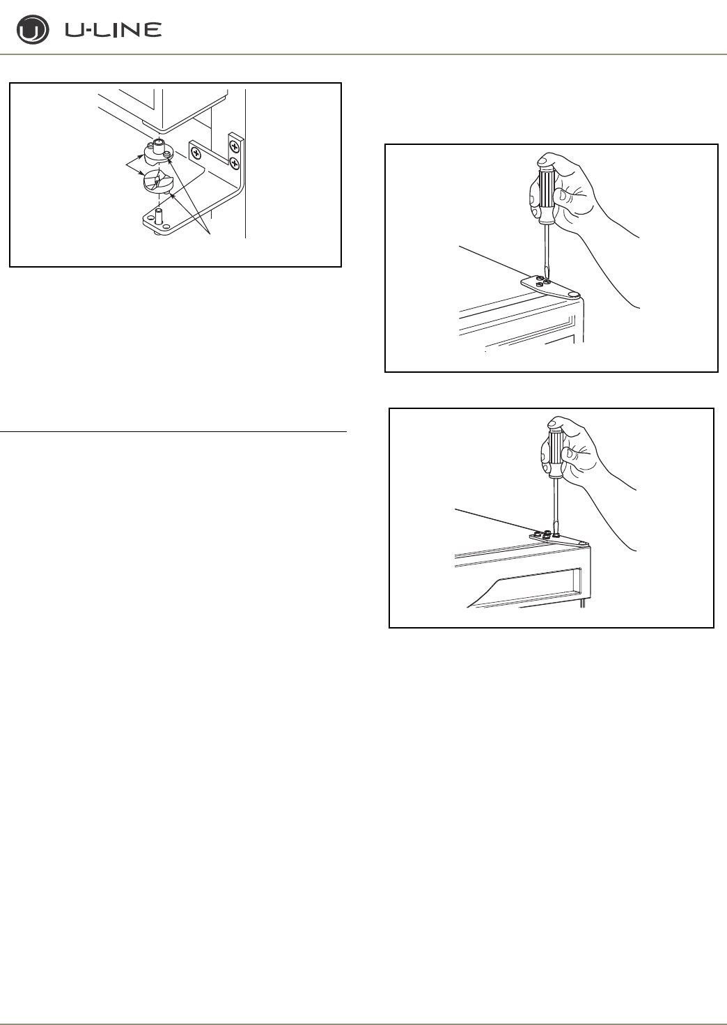
3-49
Section 3 - Service and Repair
Figure 41
8. Mount the door, install top hinge pivot pin.
Door Alignment - Origins Models
The unit’s door is aligned at the factory before shipment. However,
its alignment could have been disturbed during shipment or during
door panel installation.
IMPORTANT
IMPORTANT
Properly aligned, the door’s gasket should be firmly in
contact with the cabinet all the way around the door (no
gaps).
CHECKING DOOR ALIGNMENT
1. Carefully examine the door’s gasket to assure that it is firmly in
contact with the cabinet.
2. If the door is properly aligned, no further adjustment is necessary.
If it is not, use the following procedure.
ADJUSTING DOOR ALIGNMENT
1. Loosen (do not remove) top and bottom hinge screws (Figure
42 and Figure 43).
Figure 42
Figure 43
2. Align door squarely with cabinet. Make sure gasket is firmly in
contact with cabinet all the way around the door (no gaps).
3. Tighten bottom hinge screws.
4. Tighten top hinge screws.
Drawer Alignment
Door
Closer
Inserts
Boss
ULIN_0298a_A
ULIN_0293_A
ULIN_0104_A
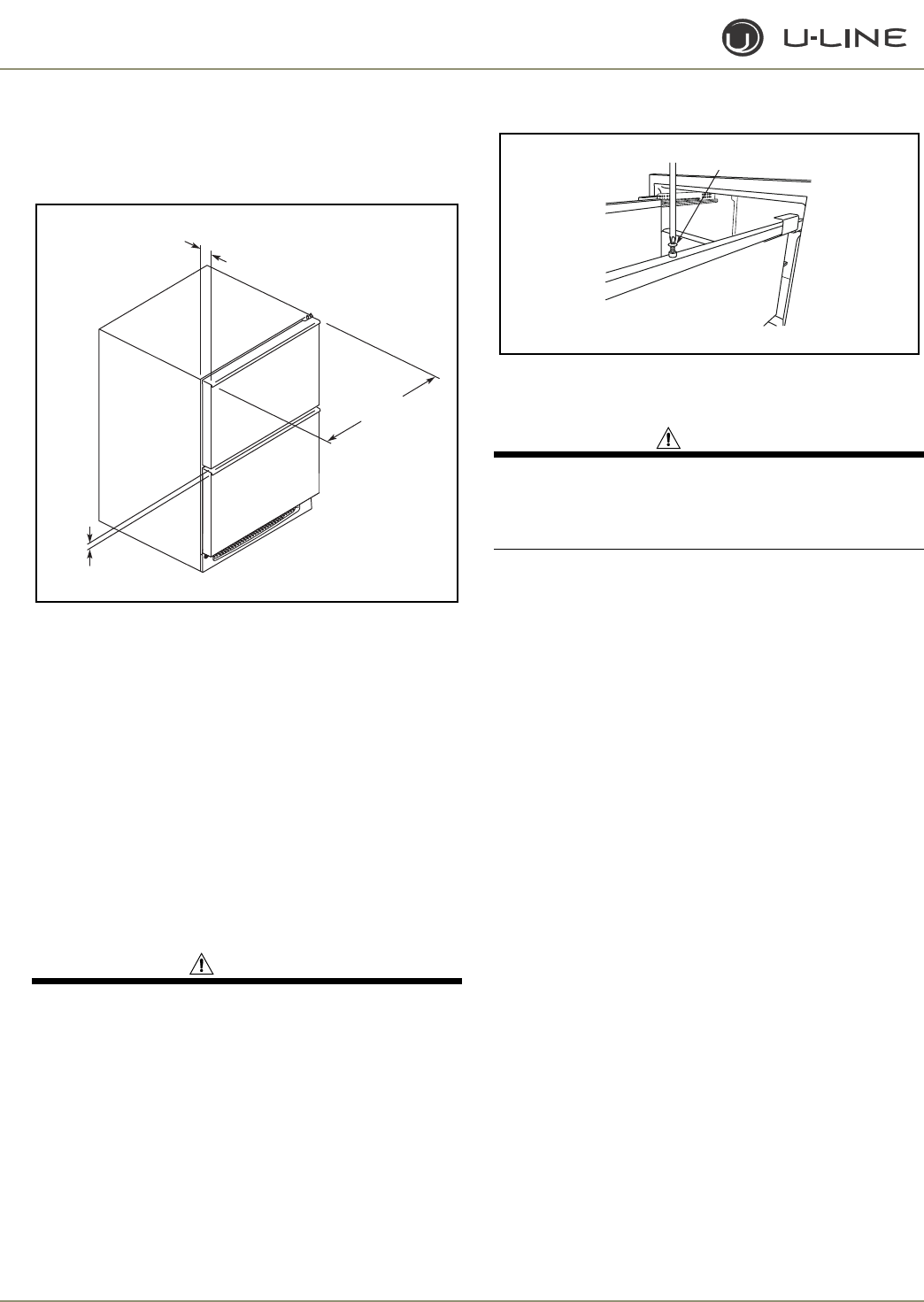
3-50
Section 3 - Service and Repair
CHECKING DRAWER ALIGNMENT
The unit’s drawers are aligned at the factory before shipment.
However, their alignment could have been disturbed during
shipment or during overlay panel installation.
Figure 44
See Figure 44. Check each drawer to confirm that it is aligned:
•Side-to-Side — When viewed from the top, the drawer front
should be square with the sides of the cabinet.
•Front-to-Back — When viewed from the side, the drawer
front should be straight with the cabinet’s sides, not cocked
forward or back.
•Top-to-Bottom — When viewed from the front, the drawer
should be level horizontally.
If both drawers are properly aligned, no further adjustment is
necessary. If either drawer is not aligned, carefully follow
instructions to remove that drawer, make the necessary
adjustment and re-install the drawer.
ADJUSTING DRAWER ALIGNMENT
WARNING
SHOCK HAZARD — The unit must be unplugged from
the wall outlet during drawer removal, adjustment and
re-installation.
DRAWER REMOVAL
1. Confirm that the unit is unplugged from wall outlet.
2. Unplug the drawer’s connection wiring (top drawer only).
3. Remove the mounting screws
(Figure 45
and
Figure 46)
.
Figure 45
4. Pull the drawer completely out of the unit.
CAUTION
Use care when handling the drawer. Drawer edges, drawer
rail and the unit’s slide may be sharp.
IMPORTANTIMPORTANT
Drawer adjustments are made by moving the slide that
carries the drawer’s rail. Minor adjustments may be made
by loosening one of the slide’s mounting screws, adjusting
the slide and retightening the screw. Severe adjustments
may be made by removing the slides’ mounting screws,
drilling new mounting holes and remounting the slide.
Aligned
Side-to-Side
Aligned
Front-to-Back
Aligned
Top-to-Bottom ULIN_0312_A
gnitnuoM
wercS
ULIN_0313_A
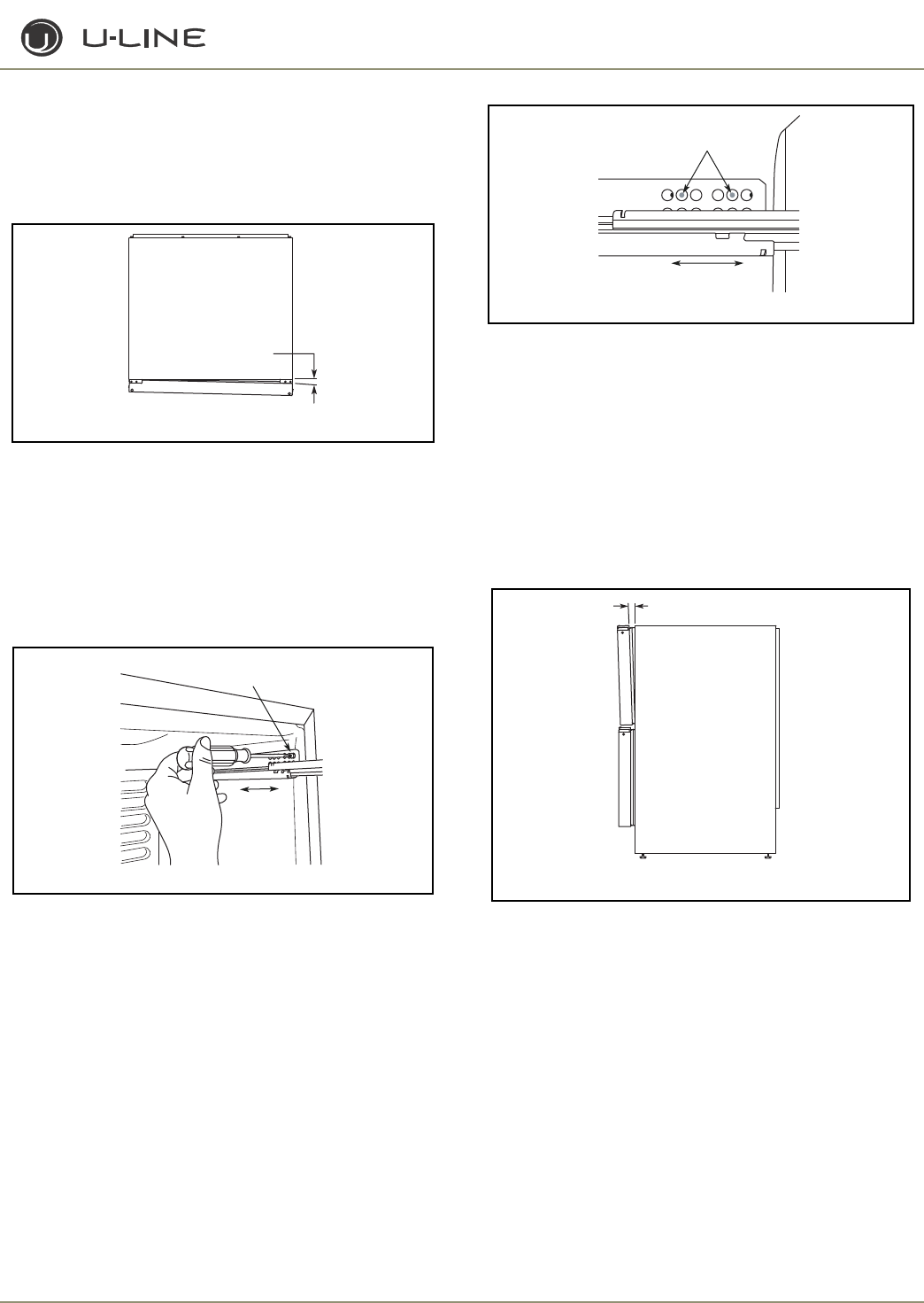
3-51
Section 3 - Service and Repair
SIDE-TO-SIDE ADJUSTMENT
See Figure 46. The drawer will need a side-to-side adjustment if,
when viewed from the top, the drawer front is not square with the
sides of the cabinet. This is caused by one of the slides being
mounted too far forward on the unit’s liner.
Figure 46
Minor Adjustment
NOTE: The mounting holes on the slide are slightly larger than the screws’
diameter.
1. Loosen the slide’s mounting screws.
2. Push the slide backward.
3. Retighten the screws
(Figure 47)
.
Figure 47
Severe Adjustment
NOTE: The slides have extra mounting holes that may be used.
1. Remove the slide’s mounting screws.
2. Reposition the slide so it is the same distance from the front of the
liner as the other slide. Measure to confirm.
3. Mark new drilling holes using different sets of mounting holes on
the slide
(Figure 48)
.
Figure 48
NOTE: Front location holes are shown. Corresponding rear holes will also
need to be marked.
4. Drill all the new holes with a #30 drill bit.
5. Remount the slide.
FRONT-TO-BACK ADJUSTMENT
See Figure 49. The drawer will need a front-to-back adjustment if,
when viewed from the side, the drawer front is cocked forward or
back. This is caused by the slide mountings not being level front to
back.
Figure 49
Minor Adjustment
NOTE: The mounting holes on the slide are slightly larger than the screws’
diameter.
1. Loosen one slide’s mounting screws.
2. Level the slide.
3. Retighten the screws
(Figure 50)
.
tinU fo weiV poT
ediS-ot-ediS dengilA toN
ULIN_0315_A
edilS hsuP
drawkcaB
nesooL
swercS gnitnuoM
ULIN_0316_A
weN llirD dna kraM
seloH gnitnuoM
edilS hsuP
drawkcaB
ULIN_0318_A
kcaB-ot-tnorF dengilA toN
tinU fo weiV ediS
ULIN_0319_A
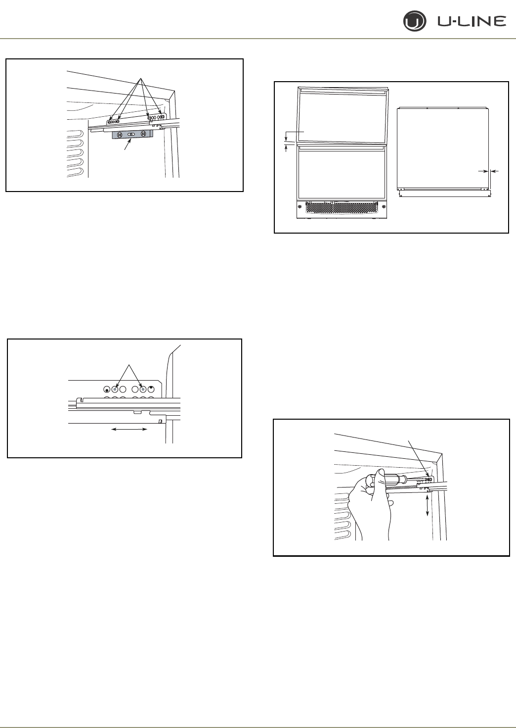
3-52
Section 3 - Service and Repair
Figure 50
4. Repeat the procedure for the other slide.
Severe Adjustment
NOTE: The slides have extra mounting holes that may be used.
1. Loosen one slide’s rear mounting screws.
2. Remove the slide’s front mounting screws.
3. Reposition the slide so it is level.
4. Mark new front drilling holes using a different set of mounting
holes on the slide
(Figure 51)
.
Figure 51
5. Drill the new holes with a #30 drill bit.
6. Remount the slide.
7. Repeat procedure for the other slide.
TOP-TO-BOTTOM (AND LEFT-TO-RIGHT)
ADJUSTMENT
Figure 52
See Figure 52. The drawer will need a top-to-bottom adjustment if,
when viewed from the front, the drawer is not level horizontally.
Viewed from the top, one side will protrude. This is caused by one of
the slides being mounted higher than the other slide on the unit’s
liner.
Minor Adjustment
NOTE: The mounting holes on the slide are slightly larger than the screws’
diameter.
1. Loosen one slide’s mounting screws.
2. Push the slide upward or downward to match the position of the
other slide.
3. Retighten the screws
(Figure 53)
.
Figure 53
4. Repeat the procedure with the other slide if necessary.
Severe Adjustment
NOTE: The slides have extra mounting holes that may be used.
1. Remove one slide’s mounting screws.
2. Reposition the slide so it is the same distance from the bottom of
the liner as the other slide. Measure to confirm.
3. Mark new drilling holes using different sets of mounting holes on
the slide
(Figure 54)
.
dluohS swercS
esooL eB
edilS eht leveL
ULIN_0320_A
weN llirD dna kraM
seloH gnitnuoM
edilS eht leveL
ULIN_0322_A
m o t t o B - o t - p o T d e n g i l A t o N
t i n U f o w e i V p o T
t h g i R - o t - t f e L d e n g i l A t o N
ULIN_0323_A
t i n U f o w e i V t n o r F
edilS hsuP
ro drawpU
drawnwoD
nesooL
swercS gnitnuoM
ULIN_0324_A
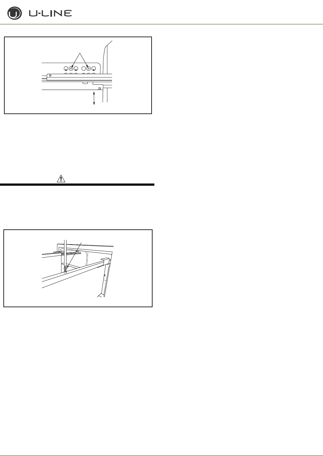
3-53
Section 3 - Service and Repair
Figure 54
NOTE: Front location holes are shown. Corresponding rear holes will also
need to be marked.
4. Drill all the new holes with a #30 drill bit.
5. Remount the slide.
RE-INSTALLATION OF DRAWER
CAUTION
Use care when handling the drawer. Drawer edges, drawer
rail and the unit’s slide may be sharp.
1. Set the drawer’s rails onto the slides.
2. Re-install the rails’ mounting screws
(Figure 55)
.
Figure 55
3. Plug in the drawer’s connection wiring (top drawer only).
weN llirD dna kraM
seloH gnitnuoM
edilS hsuP
ro drawpU
drawnwoD
ULIN_0325_A
gnitnuoM
wercS
ULIN_0313_A
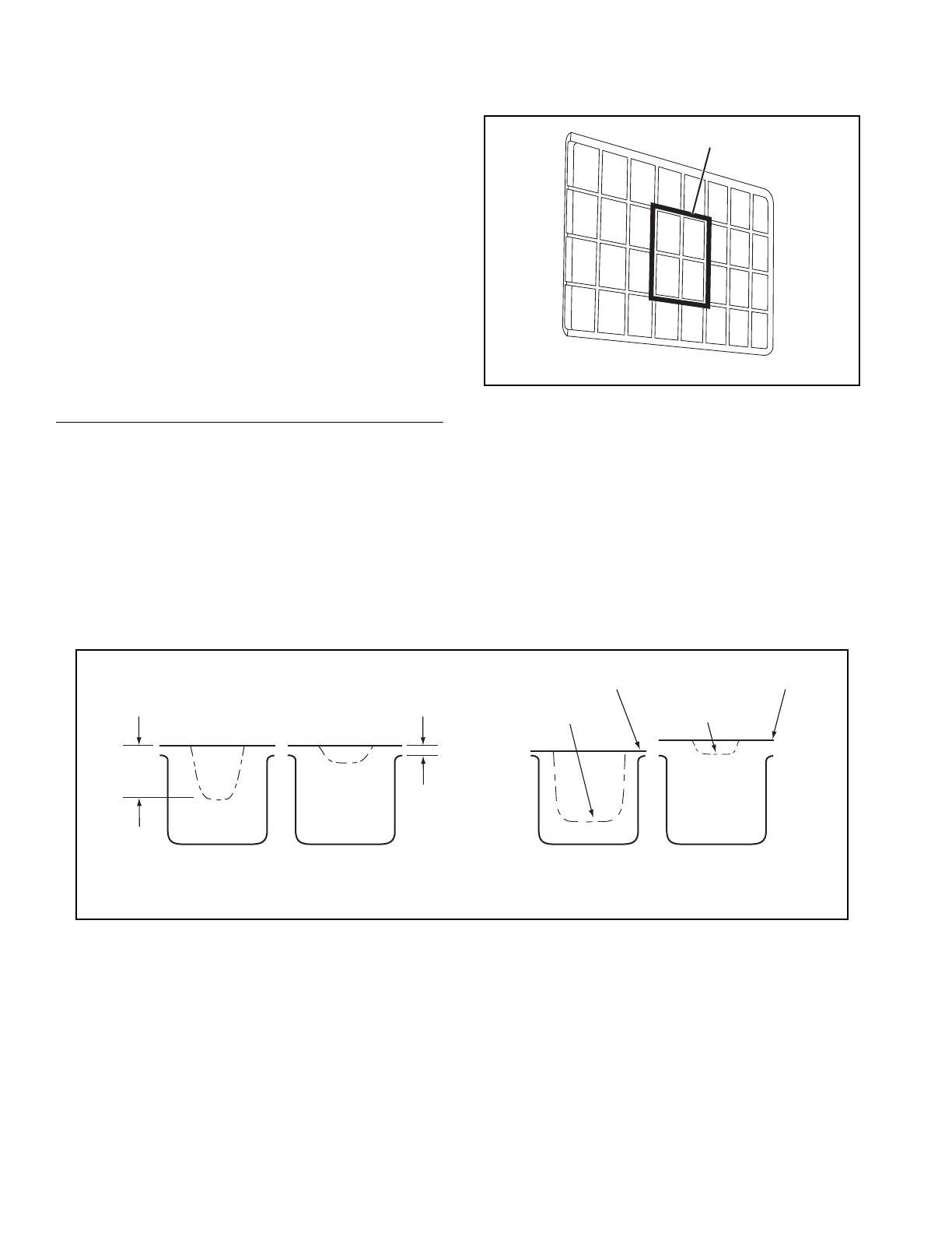
3-54
Section 3 - Service and Repair
Ice Cube Thickness Adjustment
INTERVAL - AS REQUIRED
Ice thickness adjustments are made using the control panel as follows:
1. To enter the thickness adjustment mode:
a. Touch and hold the UP ARROW button.
b. Touch and release the DOWN ARROW button three times,
then release the UP ARROW button.
c. The display will switch to “0” to confirm the thickness
adjustment mode has been selected.
2. The factory setting is “0,” and the total range of adjustment is -5 to
+5 (ideal range is -1 to +1). Use the UP ARROW button to raise
the setting and thicken the ice bridge, or the DOWN ARROW
button to lower the setting to thin the ice bridge.
IMPORTANT
IMPORTANT
Ice thickness adjustment should only be made one
increment at a time. Allow ice maker production to stabilize
for 24 hours before rechecking ice thickness.
3. Touch and release the LIGHT button key to exit the ice thickness
adjustment mode.
4. Remove all ice from the storage bin.
Figure 56
Ice cubes in any given batch will vary, so it is necessary to choose
cubes from the sample area for comparison when making
adjustments. If further adjustments are desired, repeat Steps 1
through 4.
The ice cube thickness is factory set for best overall performance.
The factory setting is designed to maintain an ice bridge of
approximately 1/16" to 1/8" under normal conditions resulting in a
dimple of approximately 1/4" to 1/2" in depth. A fuller cube with less
of a dimple results in a thicker ice bridge. As the ice bridge becomes
thicker, the tendency for the cubes to stay together as a slab
increases. A bridge thicker than 1/8" may cause cubes to overfill the
ice bucket.
Figure 57
Sample
area
ULIN_0063_A
GOOD
BRIDGE
TOO THIN
BRIDGE
TOO THICK
DIMPLE
TOO DEEP
LITTLE OR
NO DIMPLE
1/4" TO 1/2"
DIMPLE
1/16" TO 1/8"
ICE BRIDGE
BAD
ULIN_0300_A
Cube Types
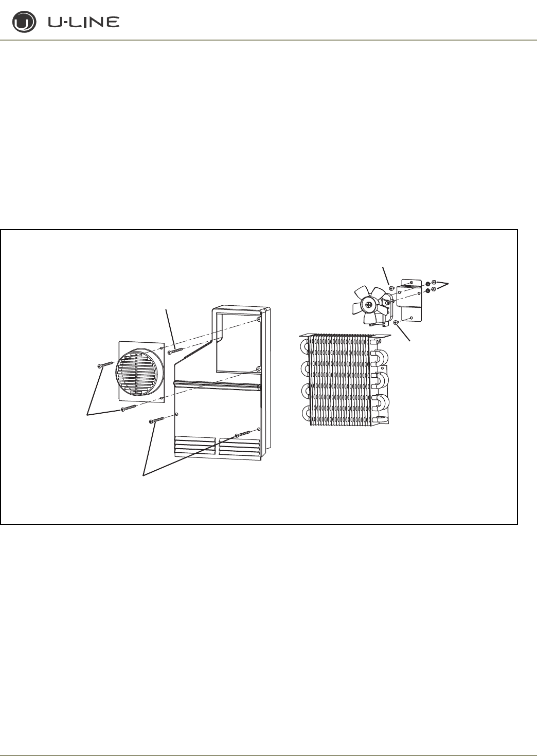
3-55
Section 3 - Service and Repair
Parts Replacement
NOTE: Echelon models do not require removal of the ice maker or freezer
housing to access the fan motor, drain or evaporator.
REPLACING EVAPORATOR FAN MOTOR
- CO2175F/2175RF
1. Disconnect unit from power source.
2. Remove two screws
(Figure 58)
from fan cover.
3. Remove two screws holding fan bracket to liner.
4. Unplug fan connection.
5. Remove two nuts holding the fan to the fan bracket.
6. Replace with new fan.
7. Plug in the fan connection.
8. Reinstall fan bracket to liner, making sure the fan wires are tucked
behind the fan bracket.
9. Reinstall unit and test.
ACCESSING EVAPORATOR OR DRAIN
- CO2175F/2175RF
1. Disconnect unit from power source.
2. Remove two screws
(Figure 58)
from fan cover.
3. Remove three screws from evaporator cover.
4. To remove, pull evaporator cover forward and turn.
Figure 58. CO2175F/2175RF
Fan cover
screws
Fan bracket screw
ULIN_0371_A
Evaporator cover
screws
Evaporator cover
screws
Fan bracket screw
Nuts
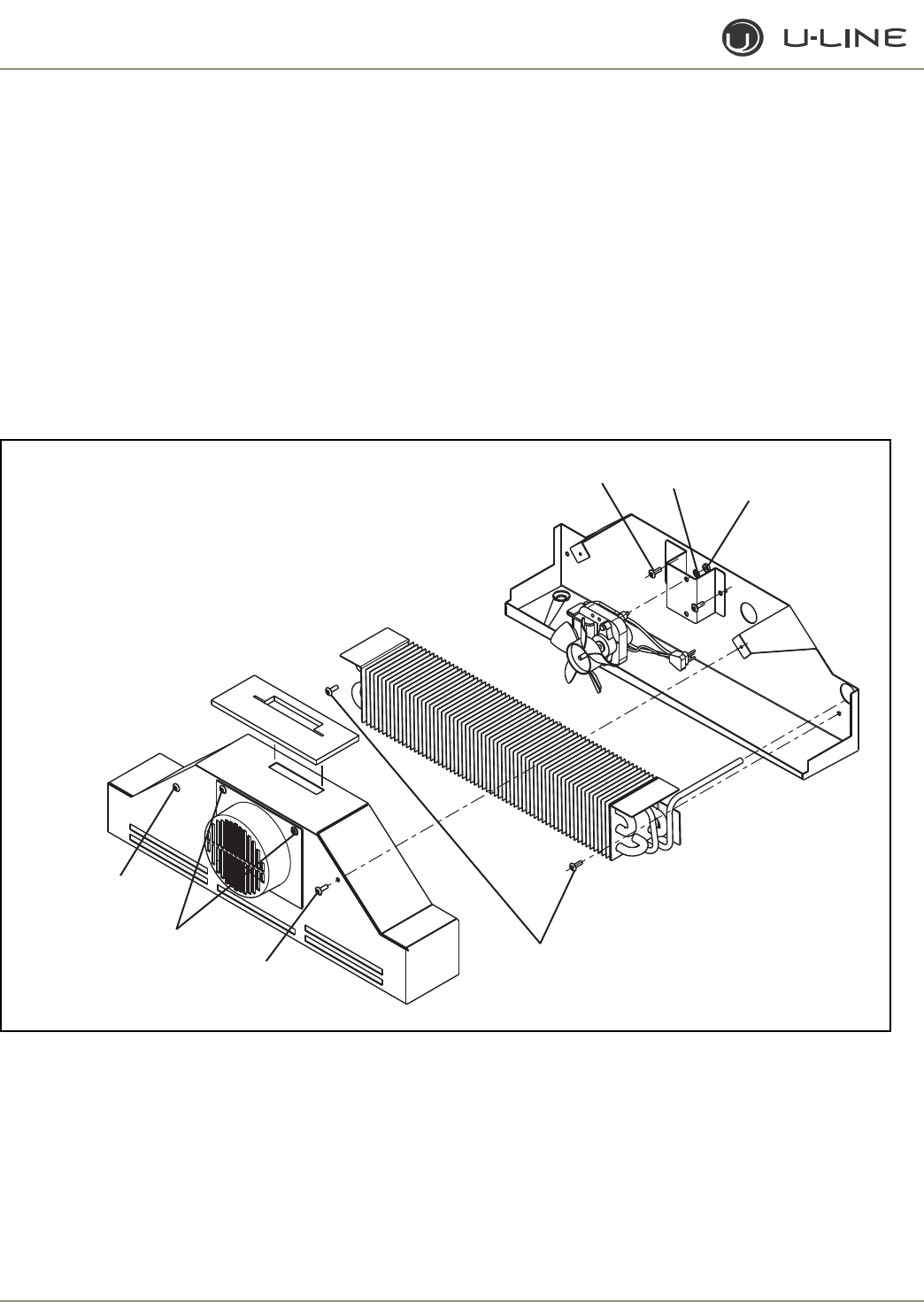
3-56
Section 3 - Service and Repair
REPLACING EVAPORATOR FAN MOTOR
- CO2175DWR
1. Disconnect unit from power source.
2. Remove two screws
(Figure 58)
holding evaporator fan cover to
evaporator cover.
3. Unplug fan connection.
4. Remove two nuts
and two washers holding the fan to the fan
bracket.
5. Replace with new fan.
6. Plug in the fan connection, making sure the fan wires are tucked
behind the fan bracket.
7. Reinstall evaporator cover.
8. Reinstall unit and test.
9. Reinstall fan bracket to liner, making sure the fan wires are tucked
behind the fan bracket.
10. Reinstall unit and test.
To access evaporator or drain:
1. Disconnect unit from power source.
2. Remove two screws
(Figure 58)
holding evaporator cover to
drain pan.
3. Remove two screws
holding evaporator to drain pan.
4. Remove two screws holding fan bracket to drain pan.
5. Unplug fan connection.
6. Reinstall parts in reverse order.
7. Reinstall unit and test.
Figure 59. CO2175DWR
ULIN_0372_A
Evaporator fan
cover screws
Washers Nuts
Fan bracket
screws
Evaporator
cover screws
Evaporator
cover screws
Evaporator to
drain pan screws
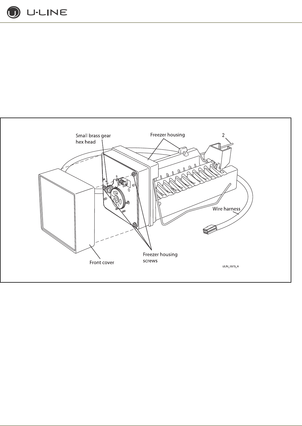
3-57
Section 3 - Service and Repair
REPLACING ICE MAKER
1. Unplug unit.
2. Disconnect ice maker wire harness at plug
(Figure 60)
.
3. Disconnect thermistor plug.
4. Remove water inlet tube.
5. Remove front cover.
6. Advance ejector blade to the 3 o’clock position by turning the 5/
16" hex head on the small brass gear counterclockwis
e
.
7. Remove three screws from wall of freezer housing.
8. Remove ice maker assembly.
9. Install new ice maker assembly.
10. Reconnect plug.
11. Reconnect thermistor plug.
12. Insert water inlet tube.
13. Apply Permagum
®
to all exit holes.
14. Install back panel.
15. Plug in unit and test.
Figure 60
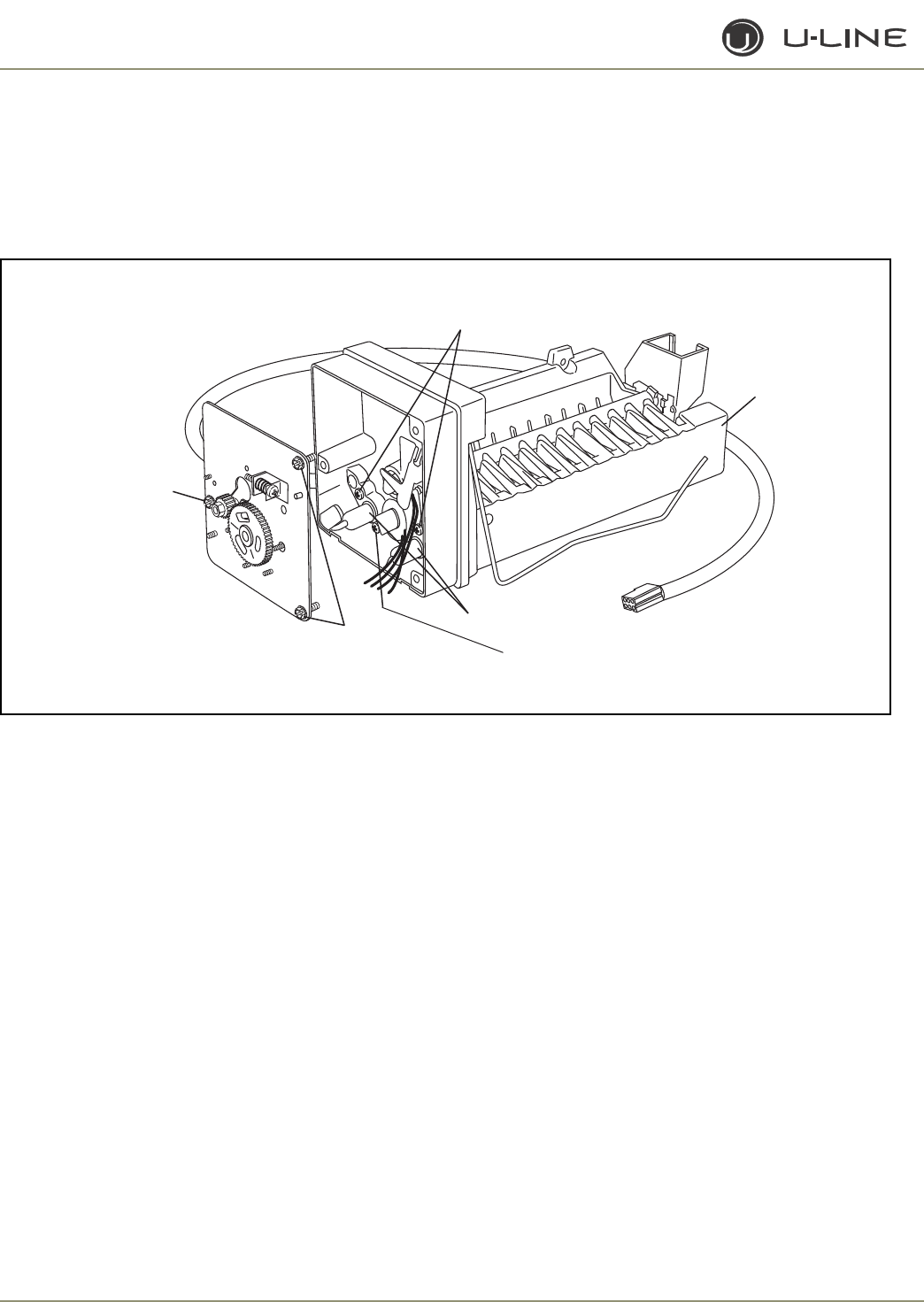
3-58
Section 3 - Service and Repair
REPLACING MOLD AND HEATER
- CO2175F/CO2175DWR
1. Remove ice maker assembly. Refer to Replacing Ice Maker
Assembly.
2. Remove one stripper screw
(Figure 61)
and stripper.
3. Remove three face plate screws
and face plate.
4. Remove one screw and detach limit switch from mold.
5. Detach heater leads.
6. Remove two screws and mold from support housing.
7. To assemble, replace parts in reverse order.
8. Install the ice maker assembly.
Figure 61
ULIN_0374_A
Face plate
screws
Face plate
screw
Mold and support
housing screws
Heater leads
Limit switch
screw
Stripper
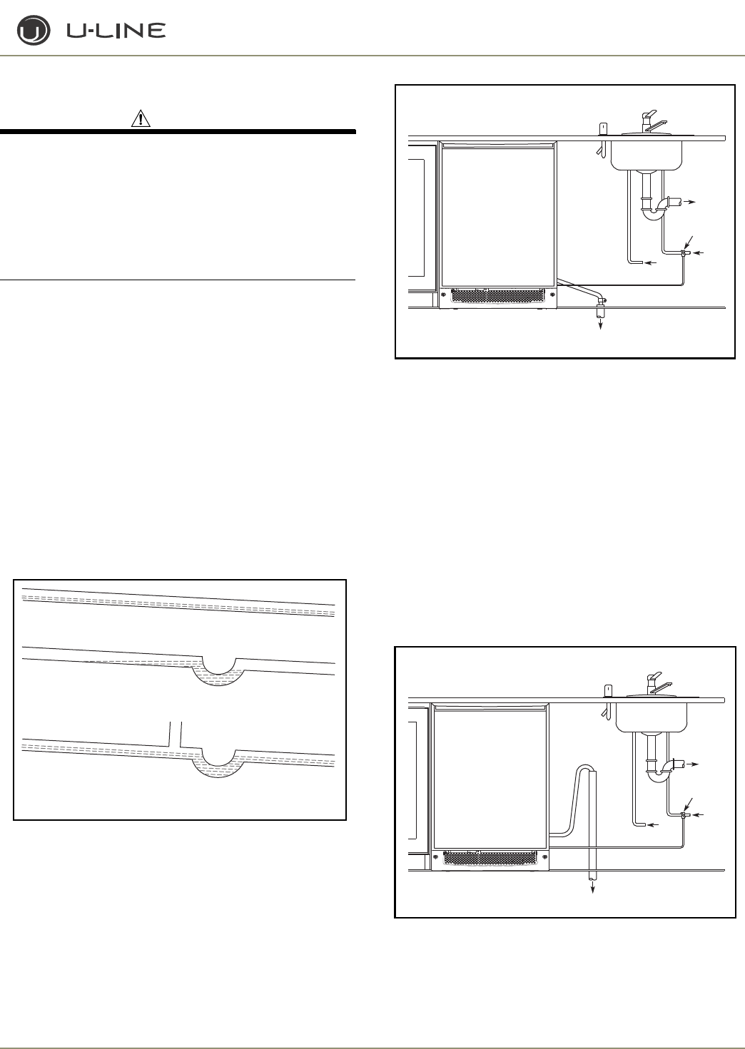
3-59
Section 3 - Service and Repair
Plumbing - CLR2160 and CLRCO2175
CAUTION
Plumbing installation must observe all state and local codes.
All water and drain connections MUST BE made by a
licensed/qualified plumbing contractor. Failure to follow
recommendations and instructions may result in damage
and/or harm.
DRAIN CONNECTION
IMPORTANT
IMPORTANT
Drain can NOT be located directly below unit. Unit has a
solid base that will not allow unit to drain below itself.
The unit can be installed using a gravity drain, a factory-installed drain
pump (U-Line P60) or a locally installed drain pump. Drain lines must
have a 5/8" inside diameter. The floor drain must be large enough to
accommodate drainage from all attached drains.
Follow these guidelines when installing drain lines to prevent water
from flowing back into the ice maker storage bin and/or potentially
flowing onto the floor, causing water damage:
GRAVITY DRAIN
A Gravity Drain may be used if:
• Drain line has at least a 1" drop per 48" of run
(1/4" per foot).
• Drain line does not create traps or created traps are vented
(Figure 62).
Figure 62
See Figure 63 for a typical gravity drain installation.
Figure 63
If using a gravity drain:
1. Attach the 5/8" ID drain connection on the back of the unit to a
5/8" OD rigid tube, using a worm clamp.
2. Attach the other end of the rigid tube to your 5/8" ID drain line
with a worm clamp.
3. Insulate the drain line, if necessary, to prevent condensation.
FACTORY-INSTALLED DRAIN PUMP
If your drain line will run up to a stand pipe, disposal assembly or
spigot assembly or does not otherwise meet the requirements for a
gravity drain, you may have ordered the CLR2160 with a U-Line P60
drain pump. See Figure 64, Figure 65 and Figure 66 for typical
installations requiring a drain pump. If you need to install a P60 drain
pump into your unit, see Locally-Installed Drain Pump.
Figure 64
Normal
Proper Drain
With Trap
Poor Drainage, Water Will Back Up
With Trap and Vent
Proper Drain
ULIN_0569_A
Waste
Waste
Cold
Water
Shut-Off
Valve
Hot
Water
Gravity Drain
ULIN_0570_A
Cold
Water
Hot
Water
Waste
Waste
Shut-Off
Valve
Stand Pipe
ULIN_0571_A
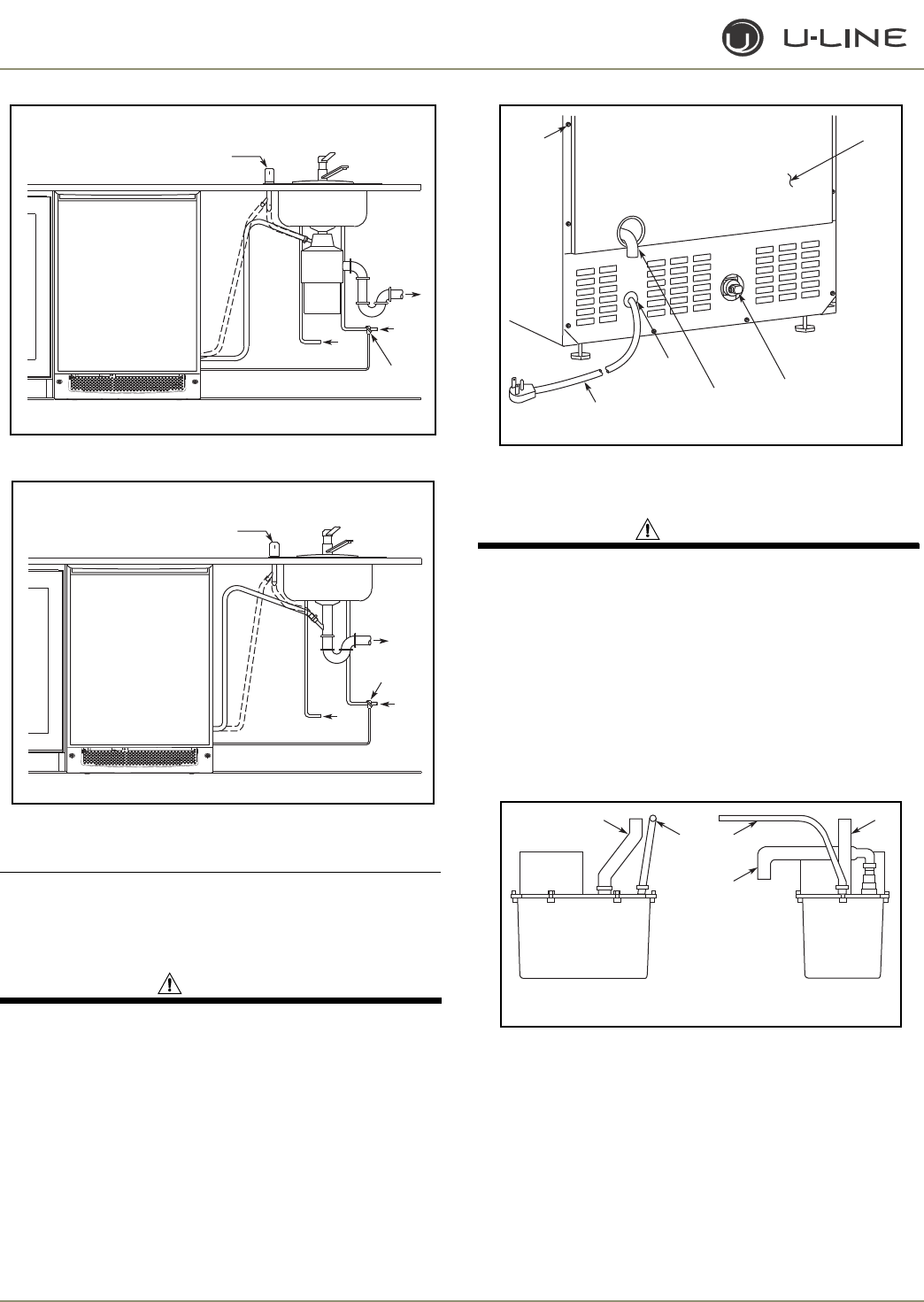
3-60
Section 3 - Service and Repair
Figure 65
Figure 66
IMPORTANT
IMPORTANT
Before installing your U-Line unit with factory- installed U-
Line P60 pump, it is extremely important to check and test
all hose connections at the drain pump. There is a possibility
that hose connections may have loosened during shipment.
WARNING
To prevent accidental electrocution, make certain that
the floor surfaces surrounding the unit are dry whenever
power is removed from, or applied to, the unit.
To check and test hose connections:
1. Make certain the unit is not plugged into an electrical outlet.
2. Carefully push the power cord grommet through the hole in the
back panel
(Figure 67)
.
Figure 67
3. Remove 12 screws and back panel.
WARNING
Back panel serves as a guard. DO NOT put your hands
inside the ice maker cabinet or attempt to touch any
components except the discharge tube during testing.
Failure to follow this warning could result in serious
personal injury or death.
4. Check that the clamps and hose connections are tight at the
following areas
(Figure 68)
:
• Discharge tube (A)
• Drain tube (B)
• Vent tube (C)
Figure 68
5. Place a suitable container beneath the pump’s discharge tube. (The
bucket must be able to hold a minimum of one gallon.)
6. Plug the ice maker power cord into a properly grounded, polarized
electrical outlet.
7. Verify pump operation by pouring one gallon of water into the ice
storage bin of the ice maker. The pump should energize and pump
the water into the container.
8. At this time, verify that all tube and clamp connections are tight
and leak free.
Air Gap
(Optional Hook-Up)
Cold
Water
Hot
Water
Waste
Shut-Off
Valve
Disposal Assembly
ULIN_0572_A
Waste
Cold
Water
Shut-Off
Valve
Hot
Water
Air Gap
(Optional Hook-Up)
Spigot Assembly
ULIN_0573_A
Power
Cord
Grommet
Drain
Fitting
Back
Panel
Water
Connection
Screws
ULIN_0574_A
Back View Side View
BB
A
CC
ULIN_0575_A
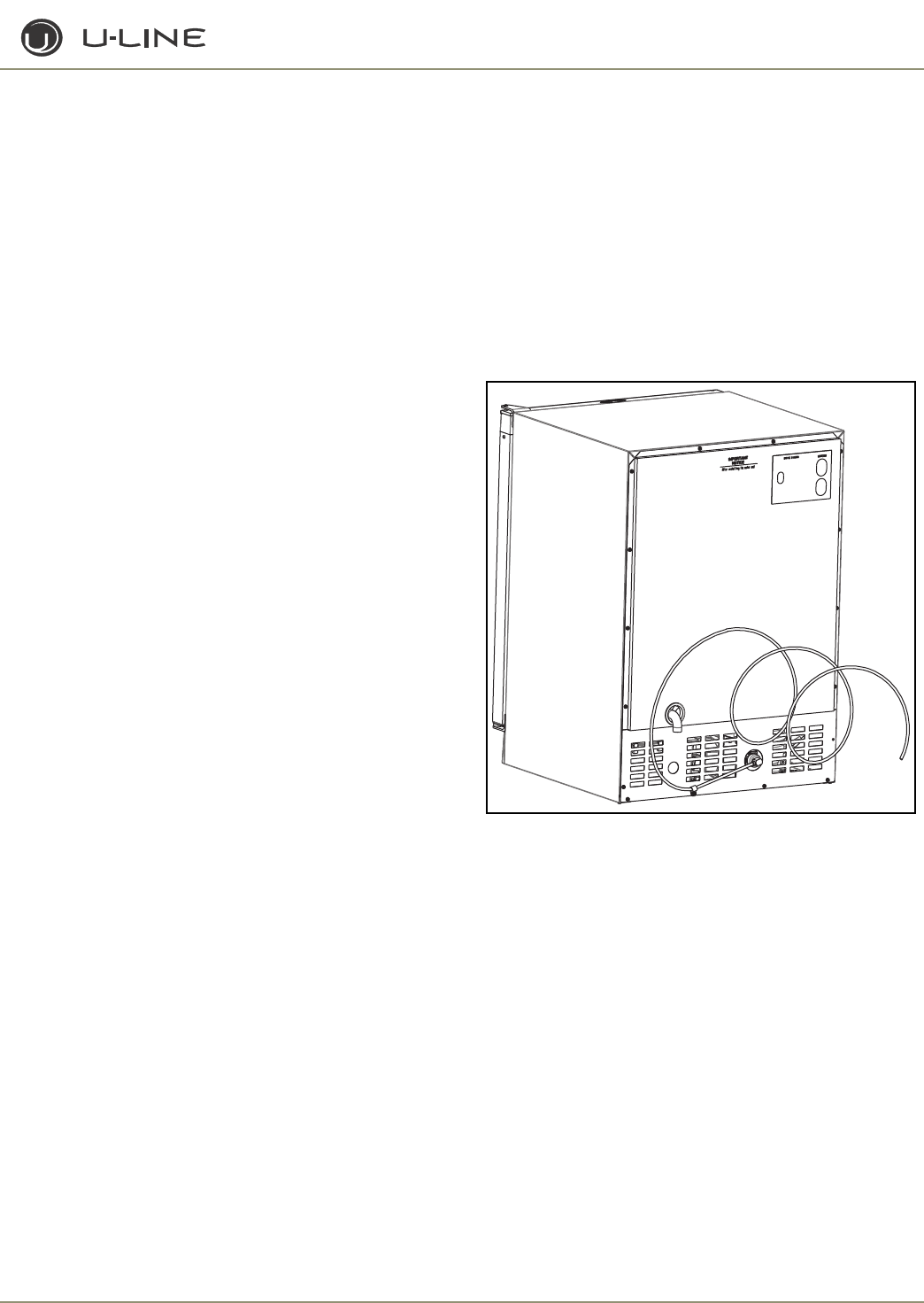
3-61
Section 3 - Service and Repair
9. Unplug unit power cord from electrical outlet.
10. Reinstall back panel.
To connect to drain:
1. Attach the 5/8" ID drain connection on the back of the unit to a
5/8" OD rigid tube, using a worm clamp.
2. Attach the other end of the rigid tube to your 5/8" ID drain line
with a worm clamp.
3. Insulate the drain line, if necessary, to prevent condensation.
LOCALLY-INSTALLED DRAIN PUMP
If a gravity drain connection is not possible, and you have not
purchased the CLR2160 with factory-installed pump, we strongly
recommend the use of the U-Line P60 drain pump. The U-Line P60
drain pump is available through your dealer, or direct from U-Line
with complete installation instructions. If a pump other than the U-
Line P60 drain pump is to be used, it must meet the following
specifications:
• It must be UL listed and have a UL listed, 120 VAC,
3-wire grounded power cord.
• It must have overall maximum outside dimensions of
8-3/4" wide x 5-3/4" deep x 7-3/4" high.
• It must have a minimum flow rate of 15 gallons per hour at 10 feet
of lift.
• It must have a sealed sump which does not allow water leakage in
the case of a power outage, restricted drain or pump failure.
• It must have a check valve in the discharge line to prevent waste
water return to the pump.
• It must have an overflow protection control which will shut off
power to the ice maker in the event of a pump failure.
• It must have an operating temperature range of 50°F to 110°F
(10°C to 40°C).
U-CLR DRAIN KIT (AVAILABLE FOR PURCHASE)
Tools Required
• 1/4" Nut driver or flat 5/16" screwdriver
•Side cutter
• Copper tubing cutter
• 12" Level
• 9/16" Open end wrench
• 7/16" Open end wrench
• Pliers
Materials Required
• (10' or more depending on water supply location) 1/4" O.D. soft
copper tubing
• **(10' or more depending on drain location) 5/8" I.D. braid
reinforced PVC drain tubing
• **(3) 11/16" to 1-1/4" Clamp range worm drive hose clamps
• **(1) Brass garden hose fitting (supplied with product)
• **(1) Nylon barbed coupling for 5/8" ID hose
• **(1) 5/8" to 7/8" adapter
** Depending on your model, your unit may have been packaged with
these items. If you need to order these items, please contact U-Line and
order Part # U-CLRDRAINKIT.
NOTE: These instructions are based on the U-Line recommendations and
common industry practice. You must consult your local plumbing codes to
ensure compliance. U-Line requires the use of copper cold water supply
connection tubing. Plastic tubing should not be used.
1. Locate the desired cold water supply location. Attach a 1/4"
copper line to this location and route the tubing to the appliance.
Leave approximately 8' of water line to be coiled behind the
appliance as shown (Figure 69). This water line should be
looped into 2 coils. This will allow the line to flex when moving
the appliance in and out of the opening.
Figure 69
2. Locate the U-Line supplied garden hose fitting. Ensure the end of
the copper tubing has been cut straight and is free of burrs. Slide
the compression nut and ferrule onto the copper tubing as shown
(Figure 70)
. Push the assembly completely into the garden hose
fitting and tighten using the two wrenches. Wait to connect this
assembly to the appliance until the drain connection is ready.
ULIN_S_165
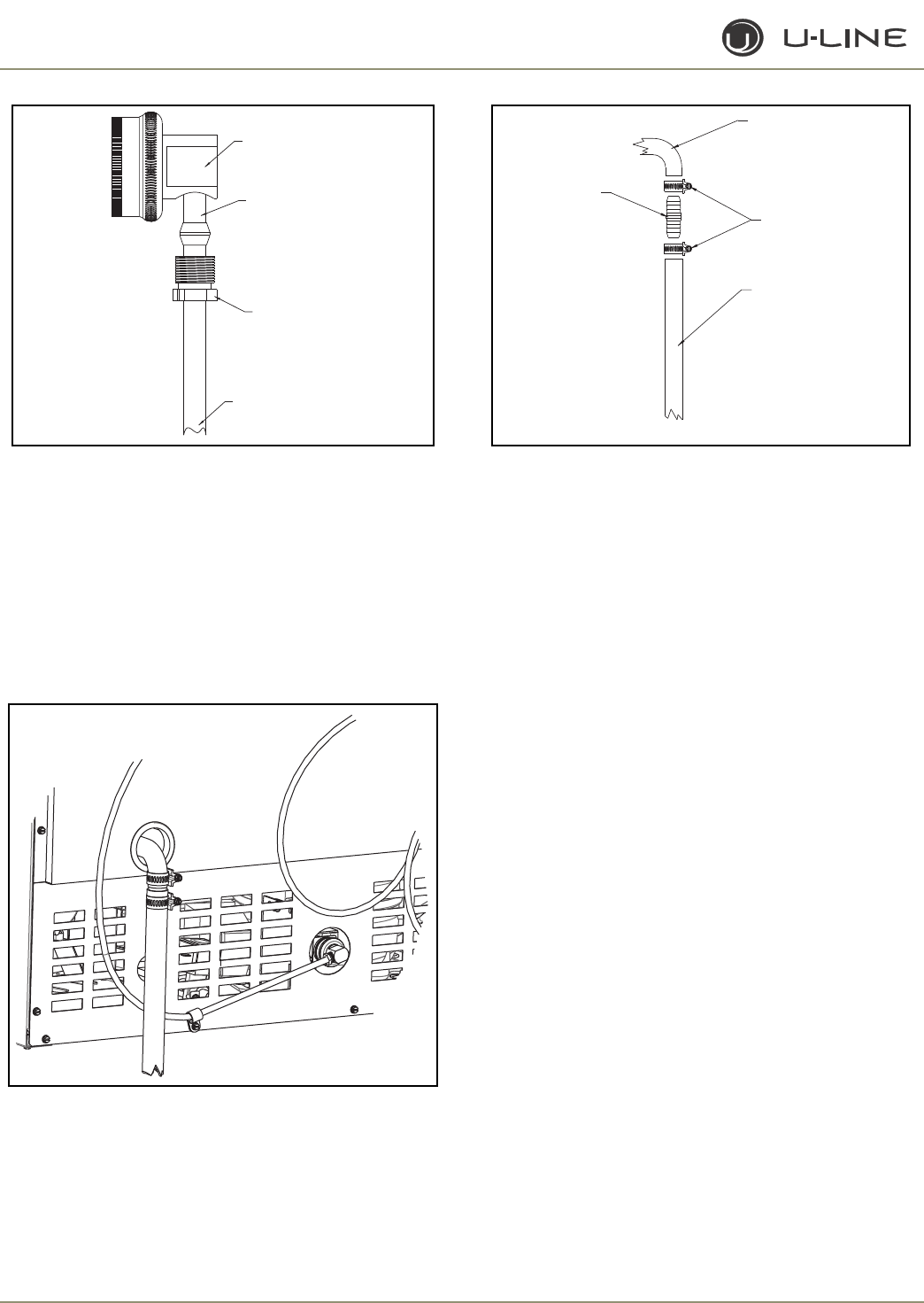
3-62
Section 3 - Service and Repair
Figure 70
3. Your U-Line icemaker requires a drain connection. This unit can be
purchased with or without a factory-installed drain pump.
If a
pump is not installed in the appliance you must use the
gravity drain style installation
OR install a pump per the
installation instructions found on www.U-Line.com.
4. Slide two hose clamps onto the drain connection on the rear of the
appliance. Insert the barbed fitting half-way into this connection.
On the other end of the barbed fitting attach the 5/8" braided
tubing. Slide a clamp onto each side of the barbed fitting as shown
(Figure 71 & 70)
.
Figure 71
Figure 72
5. Determine the location of your drain and begin to route the drain
tubing in that direction. If using the gravity drain option you must
provide 1/4" drop every foot of line. For drain pump application
you must not go higher than 10 feet of lift. The lift should be made
vertically at the beginning of the drain line. After the lift try and
provide 1/4" drop every foot of line to the drain location.
6. Connect the water supply fitting by screwing the brass garden hose
fitting to the water valve in the rear of the unit. Tighten this fitting
with a pliers. Do not use Teflon tape or joint compound on the
fitting. The rubber washer provides an adequate seal. Other
materials could cause blockage of the valve. The copper water line
should now be clamped to the rear of the unit to prevent rotation
when sliding in. Remove the clamp from the unit, slide the tube
into it and reattach using the 1/4" nut driver as shown
(Figure 71
and 70)
.
7. Plug in the unit and put the unit into OFF mode by holding the
power key for 10 seconds. Not doing this will cause the unit to fill
with water for three minutes.
8. Turn on the water supply and ensure the connections are free of
leaks.
9. Begin to push the appliance into the desired cabinet opening. The
copper tubing should remain in two coils behind the unit. While
pushing the unit into the opening continuously reroute the drain
tube to avoid kinks. The most common installation pulls the slack
into an adjacent cabinet or basement area. Again, if installing a
gravity drain, ensure you provide proper slope
9/16" Wrench
1/4" Copper Water
Supply Line
7/16" Wrench
From Water Supply
to Ice Maker
ULIN_S_0168_A
ULIN_S_0166b1_A
Drain Fitting from
Back of Unit
Worm Clamps
Drain Line
5/8" x 5/8"
Barb Connector
ULIN_S_0166b2_A
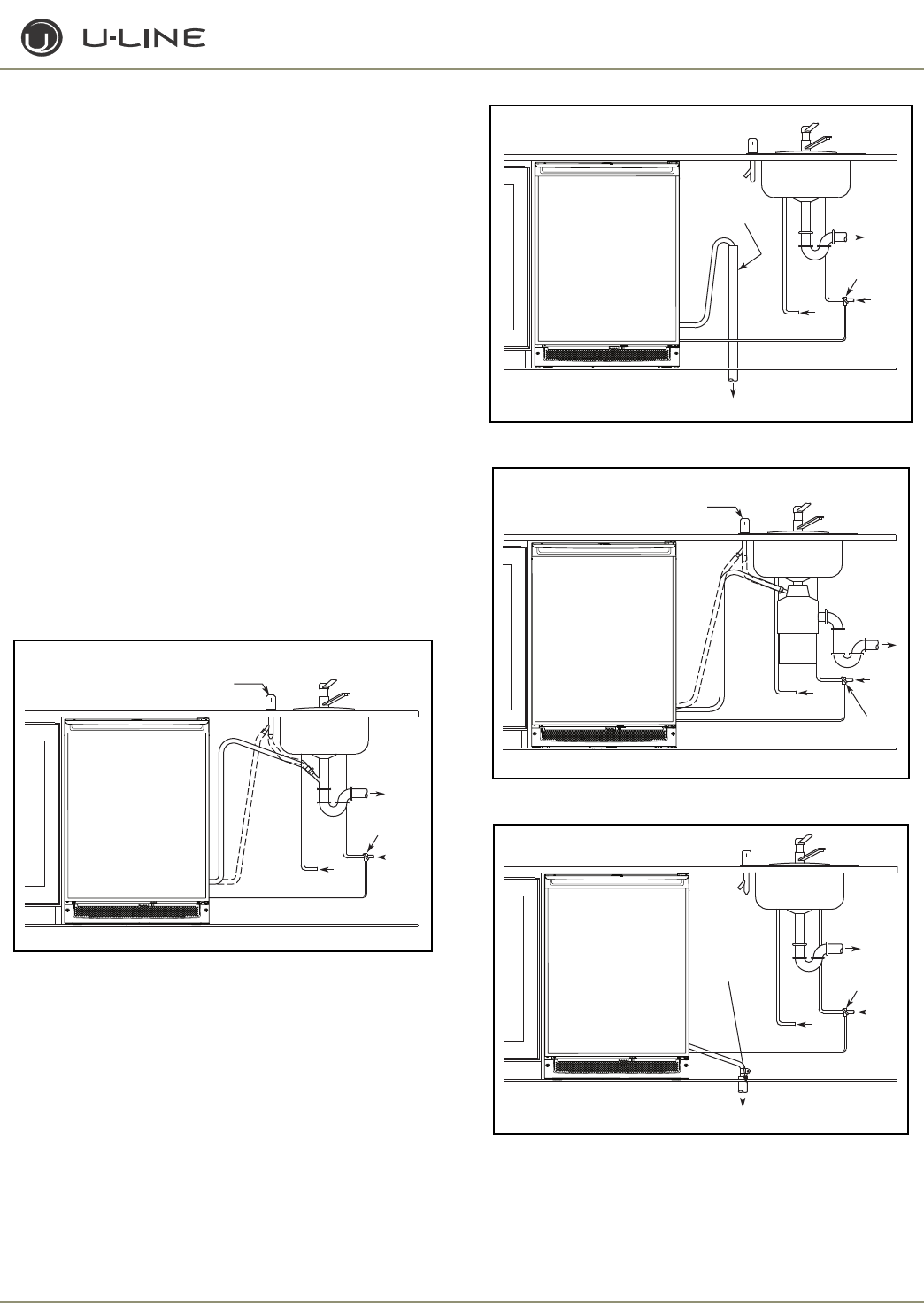
3-63
Section 3 - Service and Repair
10. Once pushed completely into the opening finish routing the drain
tubing to the desired location. Common installations use a floor
drain, standpipe, garbage disposal, or Y-branch tailpiece-type drain
connection
(Figure 73 - 76)
. After the installation is complete,
check the unit to ensure it is level both side to side and front to
back. For disposal connections an optional adapter may be
required (included with the kit) to adapt from the 7/8" connection.
11. For the gravity/floor drain or the standpipe drains it is important to
secure the drain tubing to those items to prevent it from coming
loose. For the disposal or
Y-branch tailpiece connections press the drain tube over the
barbed end on the connector. Make sure the knockout inside the
tailpiece has been removed for both types of connections. Attach
these two with a worm drive hose clamp. Depending on the size of
the
Y-branch or disposer fitting an adapter may be needed to interface
between the 5/8" hose and connection.
12. After all connections have been completed turn the unit to the ON
position. Pour one gallon of water into the ice bin and check all drain
connections for leaks. During this time also ensure that the water
flows from the bin. If the water does not flow from the bin there
may be a problem with the drain connection such as kinks or
improper slope. If your unit has a drain pump an indicator of P1 on
the display will alert to a slow or clogged drain. If any problems are
found, retrace the drain connection, correct the issue and retest
with water.
Figure 73
Figure 74
Figure 75
Figure 76
Waste
Cold
Water
Shut-Off
Valve
Hot
Water
Air Gap
(Optional Hook-Up)
Y-Branch Tailpiece
P60 Pump Required
ULIN_0600a_A
Cold
Water
Hot
Water
Waste
Waste
Shut-Off
Valve
Standpipe
P60 Pump Required
Air gap must
be left between
drain line and
water level.
ULIN_0598a_A
Air Gap
(Optional Hook-Up)
Cold
Water
Hot
Water
Waste
Shut-Off
Valve
Disposal
P60 Pump
Required
ULIN_0599a_A
Waste
Waste
Cold
Water
Shut-Off
Valve
Hot
Water
Floor Drain
Air gap must
be left between
drain line and
water level.
ULIN_0597a_A
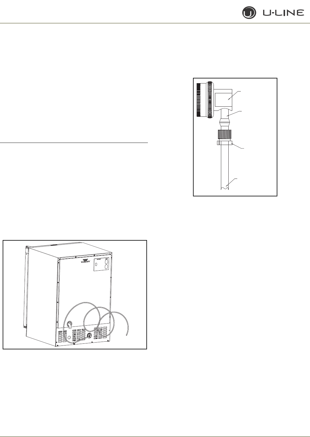
3-64
Section 3 - Service and Repair
WATER SUPPLY CONNECTION
When connecting the water supply, follow these guidelines:
• Review the local plumbing codes before you install the unit.
• Connect to the cold water supply.
• The water pressure should be between 20 and 120 psi.
• The water line MUST have a shut-off valve in the 1/4” O.D. supply
line.
• Leave approximately 8’ of water line to be coiled behind the
appliance (Figure 77). The water line should be looped into 2
coils. This will allow the unit to be removed for cleaning and
servicing. However, make certain that the tubing is not pinched or
damaged during installation.
IMPORTANT
IMPORTANT
U-Line recommends the use of copper tubing for installation
or using flexible water supply kit from U-Line, Part No.
WATERHOOKUP.
If using the flexible water supply kit, follow the instructions included
with the kit.
To connect to 1/4” copper line water supply:
1. Locate the desired cold water supply location. Attach a 1/4”
copper line to this location and route the tubing to the appliance.
Leave approximately 8’ of water line to be coiled behind the
appliance. The water line should be looped into 2 coils. This will
allow the line to flex when removing the unit for cleaning and
servicing (Figure 77).
Figure 77
2. Locate the U-Line supplied garden hose fitting. Ensure the end of
the copper tubing has been cut straight and free of burrs. Slide the
compression nut and ferrule onto the copper tubing as shown
(
Figure 78
). Push the assembly completely into the the garden
hose fitting and tighten using the two wrenches. Wait to connect
this assembly to the appliance until the drain connection is ready.
Figure 78
ULIN_S_165
9/16" Wrench
1/4" Copper Water
Supply Line
7/16" Wrench
From Water Supply
to Ice Maker
ULIN_S_0168_A
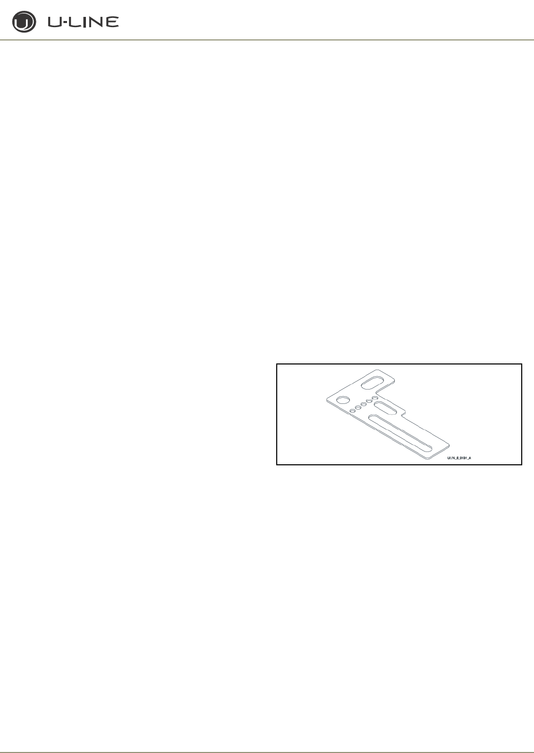
4-1
Section 4 - Parts
PARTS LISTING
How to Order Replacement Parts
1. Refer to Service Parts and locate the illustration(s) for the model
you are servicing.
2. Locate the desired part to be serviced and note the item number
assigned to it.
3. Locate the item number within the parts list. Note the full
description and the corresponding part number. If this is for a
warranty unit, indicate and record the model and serial numbers.
4. When ordering parts, it will be necessary to supply Model
Number, Serial Number, Part Number, Part Description and in
some cases Color or Voltage.
5. U-Line requires the return of the parts listed below if replaced
under warranty.
All warranty parts will be shipped at no charge as long as warranty
status has been confirmed. We require that some parts be returned
to U-line, so we may return them to our vendor. It will be noted on
your packing list if we require you to return a part or if you may field
scrap it. If U-Line requires a defective part to be returned, a prepaid
shipping label will be included with your new replacement part.
When returning parts enclose a copy of your packing list and a copy
of your labor claim, showing the model and serial number, and tag or
label the part with the nature of the defect.
Our warranty records may not match the customer's
information. In this case, a proof of purchase will be
required. If you do not have the proof of purchase at the
time the order is placed, the part will be sent net 15 days,
charged to a Visa or MasterCard or COD if you don't have an
open account with U-Line Corporation. When the proof of
purchase is provided, we will credit your credit card or U-
Line account (a check will be sent if the part was sent COD).
6. Parts may be ordered on-line, by FAX or phone:
www.U-LineService.com
onlineparts@u-line.com
FAX Number (414) 354-7905
Phone Number (414) 354-0300 or (800) 779-2547
REPLACEMENT PARTS: Use only genuine U-Line replacement
parts. The use of non-U-Line parts can reduce ice rate, cause water
to overflow from ice maker mold, damage the unit, and can void the
warranty.
ANTI-TIP KIT
Anti-Tip Kit, Part No. 80-16005-01 (BLK) or 80-16005-02 (SS), is
available for all models. Kit includes two brackets.
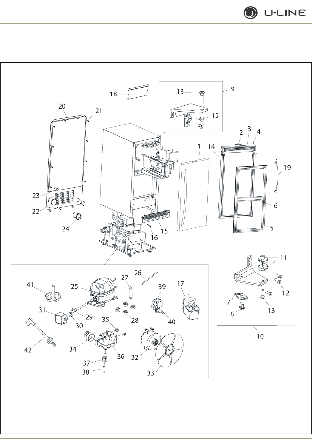
4-2
Section 4 - Parts
CLR2160 (1 of 2)

4-3
Section 4 - Parts
Item Part No. Part No. Part No. Description
Black White Stainless Steel
1 80-17071-01 80-17071-02 80-17071-03 Door Assembly, RH
N/A N/A 80-17071-13 Door Assembly, LH
2 23025 23025 23025 Nameplate
3 26071-01-S 26071-02-S N/A Handle Assembly
4 42173-BLK 42173-NAT N/A Hole plug (included with handle assembly)
5 12094-04-S 12094-06-S 12094-05-S Gasket, door
6 12095-04 12095-06 12095-05 Gasket, center (included with gasket assembly)
7 11901-1-BLK-S 11901-1-BLK-S 11994-BLK-S Pivot plate
8 42161-ZP 42161-ZP 42161-ZP Screw
9 11898-S-BLK 11898-S-KIT 11995-S-SS Hinge Assembly, top
10 11899-S-BLK 11899-S-KIT 11996-S-SS Hinge Assembly, bottom
11 31673-S 31673-S 31673-S Door Closer Assembly
12 42101-BLK 42101-ZP 42101-SS Screw, hinge (included with hinge assembly)
13 42096 42096 42096 Pivot post (included with hinge assembly)
14 41604 41725 N/A Screw, handle (included with handle assembly)
15 80-29012-01 80-29012-02 80-29012-03 Grille
16 20033-BLK 20033-ZP 20033-ZP Screw (included with grille)
17 P-60 P-60 P-60 Waste Water Pump Kit
18 14132-BLK 14132-KIT 14132-SS Front panel (board access)
19 N/A N/A 14160-01 Towel Bar Handle Assembly
20 11964-02 11964-02 11964-02 Back panel
21 41342 41342 41342 Screw, back panel
22 42125 42125 42125 Cover, solid hole
23 N/A N/A N/A Cover, perforated hole
24 41955 41955 41955 Bushing, black
25 70081-S 70081-S 70081-S Compressor, EMY70HER
26 2819 2819 2819 Process tube (included with 70081-S)
27 2693 2693 2693 Dryer (included with 70081-S)
28 31021 31021 31021 Grommet (included with 70081-S)
29 71027 71027 71027 Overload (included with 70081-S)
30 71028 71028 71028 Relay (included with 70081-S)
31 70081-CAP 70081-CAP 70081-CAP Cover (included with 70081-S)
32 5300 5300 5300 Fan motor, condenser
33 5303 5303 5303 Fan blade, condenser
34 41826 41826 41826 Fitting, water line, 90°
35 42114 42114 42114 Screw, water valve
36 2716-1 2716-1 2716-1 Water valve
37 41254 41254 41254 Compression nut (included with 404-CLR60
38 404-CLR60 404-CLR60 404-CLR60 Water line
39 73002-2 73002-2 73002-2 Coil only, Danfoss
40 73002-1-S 73002-1-S 73002-1-S Hot Gas Bypass Assembly
(includes dryer and process tube)
41 41319 41319 41319 Foot, leveler
42 2949 2949 2949 Power cord
Not N/A N/A 12091 Bushing, top pivot post
Shown
CLR2160 (1 of 2)
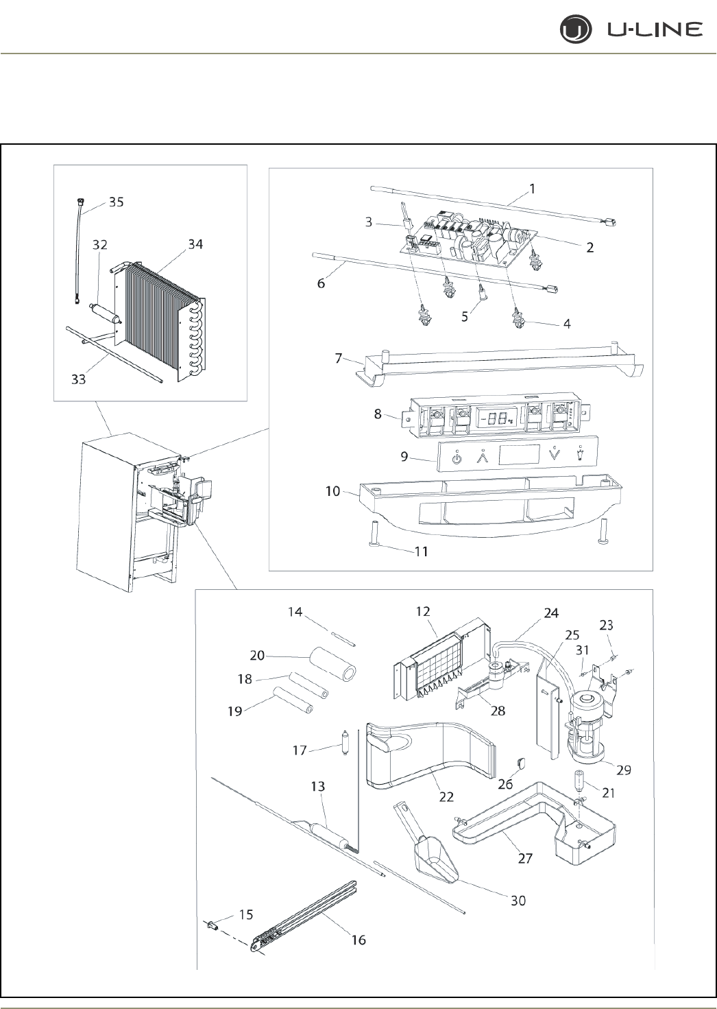
4-4
Section 4 - Parts
CLR2160 (2 of 2)

4-5
Section 4 - Parts
Item Part No. Part No. Part No. Description
Black White Stainless Steel
1 68092 68092 68092 Thermistor, white
2 68072-S 68072-S 68072-S Circuit Board Assembly
3 68080 68080 68080 Switch jumper (included with 68072-S)
4 41992 41992 41992 Support, circuit board (included with 68072-S)
5 41993 41993 41993 Support, circuit board (included with 68072-S)
6 68093 68093 68093 Liquid Line Thermistor, black
7 26086 26086 26086 Liner, baseplate
8 68074 68074 68074 Display Assembly, Echelon
9 68059-01 68059-01 68059-01 Display glass, Echelon control
10 26089 26089 26089 Housing, display
11 42162 42162 42162 Screw, 8-18 x .75, plastite
12 2276-S 2276-S 2276-S Evaporator Assembly
13 2725-S 2725-S 2725-S Heat Exchanger (included with 2276-S)
14 2819 2819 2819 Process tube (included with 2276-S)
15 31434-1 31434-1 31434-1 Push rivet, thermistor cover
16 26091 26091 26091 Cover, thermistor
17 2850 2850 2850 Dryer (included with 2276-S)
18 31154 31154 31154 Armaflex, 3/8” ID (included with 2276-S)
19 31410 31410 31410 Armaflex, 5/8” OD (included with 2276-S)
20 31636 31636 31636 Armaflex, 1-5/8” ID (included with 2276-S)
21 31619 31619 31619 Stand pipe
22 11868 11868 11868 Front cover
23 41979 41979 41979 Well Nut (included with 31613-S)
24 31615-S 31615-S 31615-S Pre-formed white tube
25 11893 11893 11893 Cover, circulation pump
26 42011 42011 42011 Hanger, ice scoop
27 11813 11813 11813 Water Trough with Drain Tube Assembly
28 11812-S 11812-S 11812-S Water Dispersion Receptacle
29 31613-S 31613-S 31613-S Circulation Pump Assembly
30 31614 31614 31614 Ice Scoop
31 41981 41981 41981 Screw (included with 31613-S)
32 2693 2693 2693 Dryer (included with 2269-S)
33 2819 2819 2819 Process tube (included with 2269-S)
34 2269-S 2269-S 2269-S Condenser Assembly
35 2892-02 2892-02 2892-02 Wire Assembly Pump(to power cord)
Not 41978 41978 41978 U-Line Cleaner (6 applications per order)
Shown
Not N/A N/A 14159-01 Commercial handle (SS Accessory only)
Shown
CLR2160 (2 of 2)
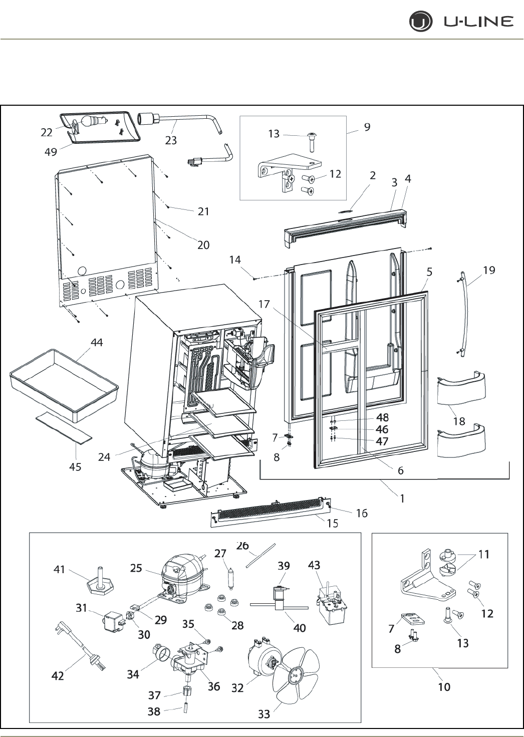
4-6
Section 4 - Parts
CLRCO2175 (1 of 4)

4-7
Section 4 - Parts
Item Part No. Part No. Part No. Description
Black White Stainless Steel
1 80-17072-01 80-17072-02 80-17072-03 Door Assembly, RH
N/A N/A 80-17072-13 Door Assembly, LH
2 23025 23025 23025 Nameplate
3 26070-01-S 26070-02-S N/A Handle Assembly
4 42173-BLK 42173-NAT N/A Hole plug (included with handle assembly)
5 12094-01 12094-03 12094-02 Gasket, door
6 12095-07 12095-08 12095-09 Gasket, vertical
7 11901-1-BLK-S 11901-1-BLK-S 11994-BLK-S Pivot plate
8 42161-ZP 42161-ZP 42161-ZP Screw, pivot plate
9 11898-S-BLK 11898-S-KIT 11995-S-SS Hinge Assembly, top
10 11899-S-BLK 11899-S-KIT 11996-S-SS Hinge Assembly, bottom
11 31673-S 31673-S 31673-S Door Closer Assembly
12 42101-BLK 42101-ZP 42101-SS Screw, hinge (included with hinge assembly)
13 42096 42096 42096 Pivot post (included with hinge assembly)
14 41604 41725 N/A Screw, handle (included with handle assembly)
15 80-29010-01 80-29010-02 80-29010-03 Grille
16 20033-BLK 20033-ZP 20033-ZP Screw (included with grille)
17 12095-01 12095-03 12095-02 Gasket, horizontal
18 31690 31690 31690 Door Shelf
19 N/A N/A 14160-01 Towel Bar Handle Assembly
20 11969-02 11969-02 11969-02 Back panel
21 41342 41342 41342 Screw, back panel
22 31317 31317 31317 Light bulb, 10W, 120V
23 2891-01 2891-01 2891-01 Light Socket Assembly
24 31696 31696 31696 Shelf
25 70078-S 70078-S 70078-S Compressor
26 2819 2819 2819 Process tube (included with 70078-S)
27 2693 2693 2693 Dryer (included with 70078-S)
28 31021 31021 31021 Grommet (included with 70078-S)
29 71011 71011 71011 Overload (included with 70078-S)
30 71012 71012 71012 Relay (included with 70078-S)
31 70078-CAP 70078-CAP 70078-CAP Cover (included with 70078-S)
Not 41978 41978 41978 U-Line Cleaner (6 applications per order)
Shown
Not N/A N/A 14159-01 Commercial handle (SS accessory only)
Shown
CLRCO2175 (1 of 4)
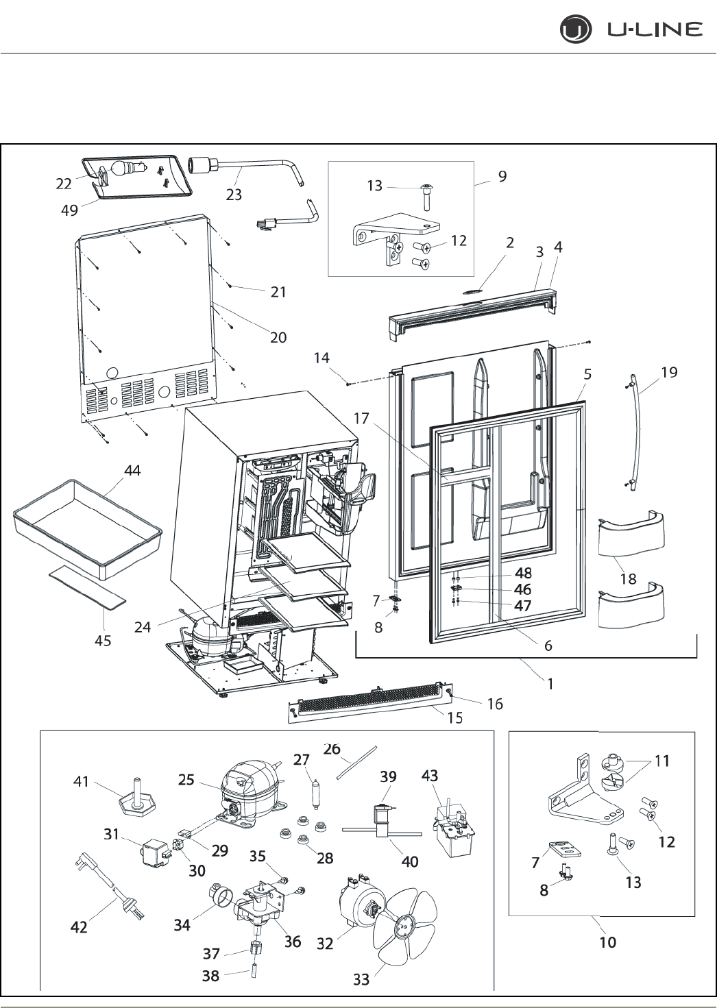
4-8
Section 4 - Parts
CLRCO2175 (2 of 4)

4-9
Section 4 - Parts
CLRCO2175 (2 of 4)
Item Part No. Part No. Part No. Description
Black White Stainless Steel
32 5300 5300 5300 Fan motor, condenser
33 5303 5303 5303 Fan blade, condenser
34 41826 41826 41826 Fitting, water line, 90°
35 42114 42114 42114 Screw, water valve
36 2716 2716 2716 Water valve
37 41254 41254 41254 Compression nut (included with water line)
38 41223-05 41223-05 41223-05 Water line
39 73001-S 73001-S 73001-S Coil only, Parker
40 73000-S 73000-S 73000-S Hot Gas Bypass Assembly
(includes dryer and process tube)
41 41319 41319 41319 Foot, leveler
42 2947 2947 2947 Power cord
43 P-60 P-60 P-60 Waste Water Pump Kit
44 31550-1-S 31550-1-S 31550-1-S Drain Pan Assembly
45 31664 31664 31664 Tape (included with #44)
46 66016 66016 66016 Magnet
47 20050 20050 20050 Screw, spacer
48 66019 66019 66019 Spacer, magnet
49 11859 11859 11859 Lens, light housing
Not N/A N/A 12091 Bushing, top pivot post
Shown
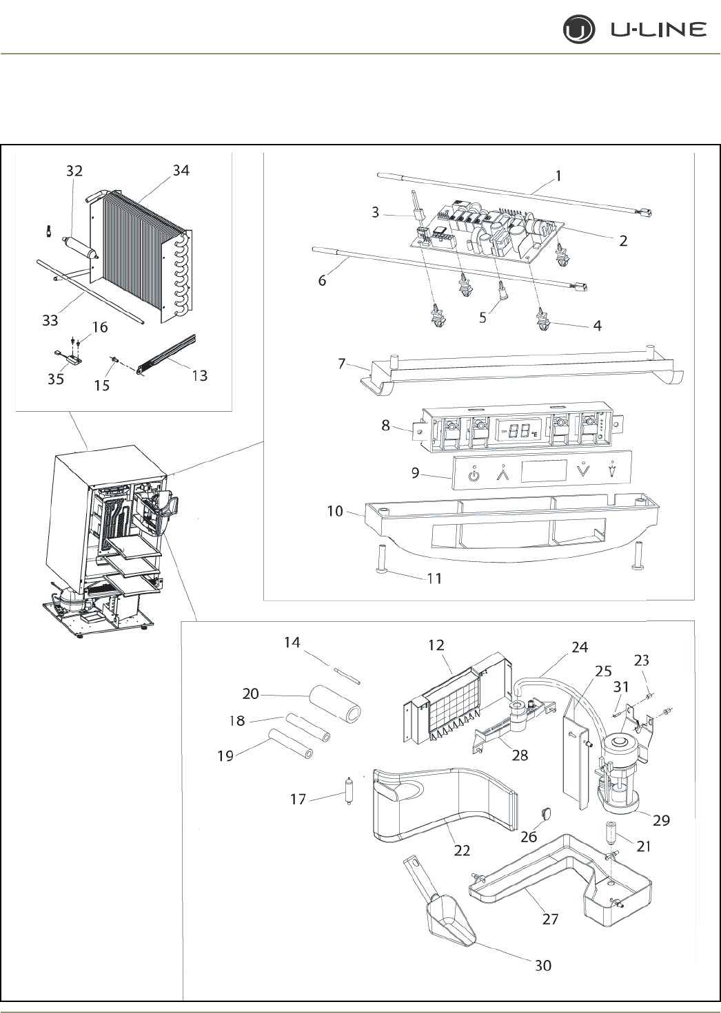
4-10
Section 4 - Parts
CLRCO2175 (3 of 4)

4-11
Section 4 - Parts
CLRCO2175 (3 of 4)
Item Part No. Part No. Part No. Description
Black White Stainless Steel
1 68092 68092 68092 Thermistor, white
2 68072-S 68072-S 68072-S Circuit Board Assembly
3 68080 68080 68080 Switch jumper (included with 68072-S)
4 41992 41992 41992 Support, circuit board (included with 68072-S)
5 41993 41993 41993 Support, circuit board (included with 68072-S)
6 68093 68093 68093 Liquid Line Thermistor, black
7 26086 26086 26086 Liner, baseplate
8 68074 68074 68074 Display Assembly, Echelon
9 68059-01 68059-01 68059-01 Display glass, Echelon control
10 26089 26089 26089 Housing, display
11 42162 42162 42162 Screw, 8-18 x .75, plastite
12 2276-CLRCO-S 2276-CLRCO-S 2276-CLRCO-S Evaporator Assembly
13 26091 26091 26091 Cover, thermistor
14 2819 2819 2819 Process tube (included with 2276-CLRCO-S)
15 31434-1 31434-1 31434-1 Rivet, thermistor cover
16 20026 20026 20026 Screw, reed switch
17 2693 2693 2693 Dryer (included with 2276-CLRCO-S)
18 72000 72000 72000 Armaflex, 3/8” ID (included with 2276-CLRCO-S)
19 31410 31410 31410 Armaflex, 5/8” OD (included with 2276-CLRCO-S)
20 31636 31636 31636 Armaflex, 1-5/8” ID (included with 2276-CLRCO-S)
21 31619 31619 31619 Stand pipe
22 12070-01 12070-01 12070-01 Front cover
23 41979 41979 41979 Well Nut (included with 31613-S)
24 31615-S 31615-S 31615-S Pre-formed white tube
25 12057-01 12057-01 12057-01 Cover, circulation pump
26 42011 42011 42011 Hanger, ice scoop
27 12068-01 12068-01 12068-01 Water Trough with Drain Tube Assembly
28 11812-S 11812-S 11812-S Water Dispersion Receptacle
29 31613-S 31613-S 31613-S Circulation Pump Assembly
30 31614 31614 31614 Ice Scoop
31 41981 41981 41981 Screw (included with 31613-S)
32 2693 2693 2693 Dryer (included with 2269-S)
33 2819 2819 2819 Process tube (included with 2269-S)
34 2269-S 2269-S 2269-S Condenser Assembly
35 66010 66010 66010 Reed Switch
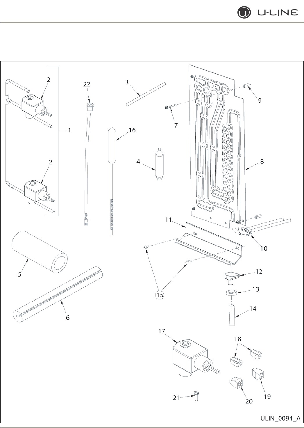
4-12
Section 4 - Parts
CLRCO2175 (4 OF 4)

4-13
Section 4 - Parts
CLRCO2175 (4 of 4)
Item Part No. Part No. Part No. Description
Black White Stainless Steel
1 80-37005-00-S 80-37005-00-S 80-37005-00-S Valve Manifold Assembly
(includes dryer and process tube)
2 73004 73004 73004 Bypass Valve (included with 80-37005-00-S)
3 2819 2819 2819 Process tube (included with 80-37005-00-S)
4 2693 2693 2693 Dryer (included with 80-37005-00-S)
5 31636 31636 31636 Armaflex (included with 80-37005-00-S)
6 75000 75000 75000 Armaflex, split (included with 80-37005-00-S)
7 41855 41855 41855 Screw
8 2878-02-S 2878-02-S 2878-02-S Refrigerator Evaporator
(includes dryer and process tube)
9 31213 31213 31213 Spacer, evaporator
10 31386-02 31386-02 31386-02 Bushing
11 31391-5 31391-5 31391-5 Drain trough
12 26008 26008 26008 Funnel drain cup
13 31578 31578 31578 Washer, drain tube
14 31731 31731 31731 Formed drain tube
15 31434-1 31434-1 31434-1 Rivet, white, large
16 72006-S 72006-S 72006-S Heat Exchanger (includes dryer and process tube)
17 BF4CO5-S BF4CO5-S BF4CO5-S Refrigeration Coil Assembly (includes 2 coils)
18 66013 66013 66013 Connector, 2 port, yellow
(included with BF4CO5-S)
19 66014 66014 66014 Connector, 4 port, green
(included with BF4CO5-S)
20 66015 66015 66015 Connector, 4 port, orange
(included with BF4CO5-S)
21 41342 41342 41342 Screw (included with BF4O5-S)
22 2892-02 2892-02 2892-02 Wire Assembly Pump to Power Cord
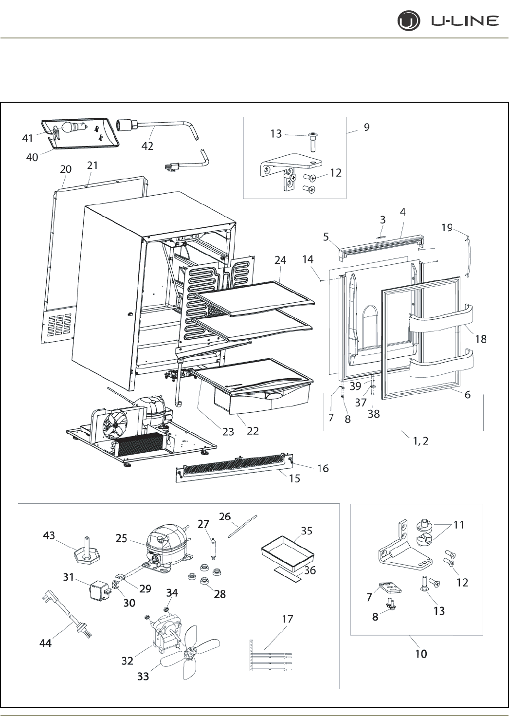
4-14
Section 4 - Parts
2175R (1 of 2)

4-15
Section 4 - Parts
Item Part No. Part No. Part No. Description
Black White Stainless Steel
1 80-17060-01 80-17060-02 80-17075-01 Door Assembly, RH
2 N/A N/A 80-17075-02 Door Assembly, LH
3 23025 23025 23025 Nameplate
4 26070-01-S 26070-02-S N/A Handle Assembly
5 42173-BLK 42173-NAT N/A Hole plug (included with handle assembly)
6 12094-01 12094-03 12094-02 Gasket, door
7 11901-1-BLK-S 11901-1-BLK-S 11994-BLK-S Pivot plate
8 42161-ZP 42161-ZP 42161-ZP Screw, pivot plate
9 11898-S-BLK 11898-S-KIT 11995-S-SS Hinge Assembly, top
10 11899-S-BLK 11899-S-KIT 11996-S-SS Hinge Assembly, bottom
11 31673-S 31673-S 31673-S Door Closer Assembly
12 42101-BLK 42101-ZP 42101-SS Screw, hinge (included with hinge assembly)
13 42096 42096 42096 Pivot post (included with hinge assembly)
14 41604 41725 N/A Screw, handle (included with handle assembly)
15 80-29010-01 80-29010-02 80-29010-03 Grille
16 20033-BLK 20033-ZP 20033-ZP Screw (included with grille)
17 2945 2945 2945 Jumper wire, power cord
18 31686 31686 31686 Door Shelf
19 N/A N/A 14160-01 Towel Bar Handle Assembly
20 11969 11969 11969 Back panel
21 41342 41342 41342 Screw, back panel
22 31685 31685 31685 Crisper drawer
23 40021 40021 40021 Crisper shelf
24 40020 40020 40020 Glass shelf
25 5400-S 5400-S 5400-S Compressor
26 2800 2800 2800 Process tube (included with 5400-S)
27 2694 2694 2694 Dryer (included with 5400-S)
28 31021 31021 31021 Grommet (included with 5400-S)
29 5411 5411 5411 Overload (included with 5400-S)
30 5412 5412 5412 Relay (included with 5400-S)
31 5400-CAP 5400-CAP 5400-CAP Cover (included with 5400-S)
32 5263-S 5263-S 5263-S Fan motor, condenser
33 5188 5188 5188 Fan blade, condenser
34 41787 41787 41787 Nut (included with 5263-S)
35 31550-1-S 31550-1-S 31550-1-S Drain Pan Assembly
36 31664 31664 31664 Tape (included with #35)
37 66016 66016 66016 Magnet
38 20050 20050 20050 Screw, magnet
39 66019 66019 66019 Spacer, nylon
40 11859 11859 11859 Lens, light housing
41 31317 31317 31317 Light bulb, 10W, 120V
42 2891-01 2891-01 2891-01 Light Socket Assembly
43 41319 41319 41319 Foot, leveler
44 2938-2 2938-2 2938-2 Power cord
2175R (1 of 2)
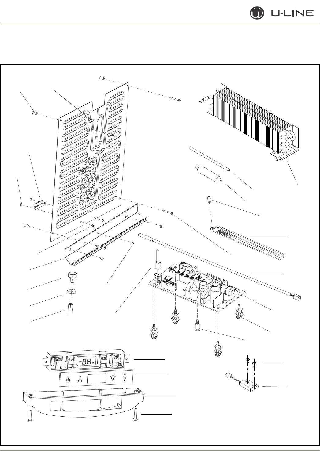
4-16
Section 4 - Parts
1
2
3
4
5
6
7
8
9
10
11
12
18
17
16
15
14
13
19
20
21
22
23
24
25
26 27
2175R (2 of 2)

4-17
Section 4 - Parts
Item Part No. Part No. Part No. Description
Black White Stainless Steel
1 2303-S 2303-S 2303-S Condenser Assembly**
2 2800 2800 2800 Process tube
3 2694 2694 2694 Dryer
4 31434-1 31434-1 31434-1 Rivet, thermistor cover
5 26091 26091 26091 Cover, thermistor
6 41855 41855 41855 Screw, Evaporator
7 68092 68092 68092 Thermistor, quick connect white
8 68072-S 68072-S 68072-S Circuit Board Assembly
9 41992 41992 41992 Support, circuit board (included with 68072-S)
10 41993 41993 41993 Support, circuit board (included with 68072-S)
11 20026 20026 20026 Screw, reed switch
12 66010 66010 66010 Reed Switch
13 42162 42162 42162 Screw, 8-18 x .75, plastite
14 26089 26089 26089 Housing, display
15 68059-01 68059-01 68059-01 Display glass, Echelon control
16 68074 68074 68074 Display Assembly, Echelon
17 68080 68080 68080 Switch jumper (included with 68072-S)
18 21012-WHT 21012-WHT 21012-WHT Rivet, white
19 31726 31726 31726 Formed drain tube
20 31578 31578 31578 Washer, drain tube
21 11508 11508 11508 Drain cup
22 31391-3 31391-3 31391-3 Drain trough
23 41156 41156 41156 Screw, stainless steel
24 41158 41158 41158 Nut
25 11835 11835 11835 Clamp, thermistor
26 31213 31213 31213 Spacer, Evaporator
27 2333-S 2333-S 2333-S Evaporator Assembly**
Not N/A N/A 12091 Bushing, top pivot post
Shown
Not N/A N/A 14159-01 Commercial handle (SS accessory only)
Shown
Not 2950-01 2950-01 2950-01 Wire connector, 12-pin
Shown
**Part Includes Dryer & Process Tube
2175R (2 of 2)
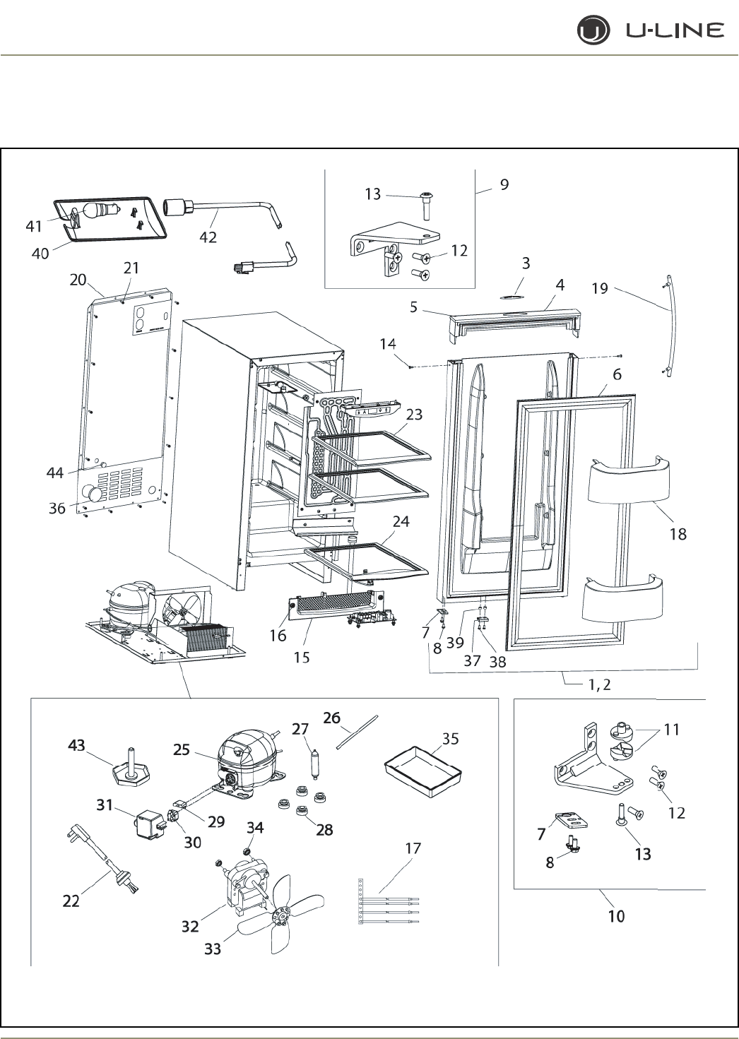
4-18
Section 4 - Parts
2115R (1 of 2)

4-19
Section 4 - Parts
Item Part No. Part No. Part No. Description
Black White Stainless Steel
1 80-17064-01 80-17064-02 80-17080-01 Door Assembly, RH
2 N/A N/A 80-17080-02 Door Assembly, LH
3 23025 23025 23025 Nameplate
4 26071-01-S 26071-02-S N/A Handle Assembly
5 42173-BLK 42173-NAT N/A Hole plug (included with handle assembly)
6 12094-04 12094-06 12094-05 Gasket, door
7 11901-1-BLK-S 11901-1BLK-S 11994-BLK-S Pivot plate
8 42161-ZP 42161-ZP 42161-ZP Screw, pivot plate
9 11898-S-BLK 11898-S-KIT 11995-S-SS Hinge Assembly, top
10 11899-S-BLK 11899-S-KIT 11996-S-SS Hinge Assembly, bottom
11 31673-S 31673-S 31673-S Door Closer Assembly
12 42101-BLK 42101-ZP 42101-SS Screw, hinge (included with hinge assembly)
13 42096 42096 42096 Pivot post (included with hinge assembly)
14 41604 41725 N/A Screw, handle (included with handle assembly)
15 80-29012-01 80-29012-02 80-29012-03 Grille
16 20033-BLK 20033-ZP 20033-ZP Screw (included with grille)
17 2945 2945 2945 Jumper wire, power cord
18 31690 31690 31690 Door Shelf
19 N/A N/A 14160-01 Towel Bar Handle Assembly
20 11964-01 11964-01 11964-01 Back panel
21 41342 41342 41342 Screw, back panel
22 2938-2 2938-2 2938-2 Power cord
23 31704 31704 31704 Glass shelf, upper
24 31703 31703 31703 Glass shelf, lower
25 5400-S 5400-S 5400-S Compressor
26 2800 2800 2800 Process tube (included with 5400-S)
27 2694 2694 2694 Dryer (included with 5400-S)
28 31021 31021 31021 Grommet (included with 5400-S)
29 5411 5411 5411 Overload (included with 5400-S)
30 5412 5412 5412 Relay (included with 5400-S)
31 5400-CAP 5400-CAP 5400-CAP Cover (included with 5400-S)
32 5263-S 5263-S 5263-S Fan motor, condenser
33 5188 5188 5188 Fan blade, condenser
34 41787 41787 41787 Nut (included with 5263-S)
35 31385 31385 31385 Drain Pan
36 42126 42126 42126 Hole cover, perforated
37 66016 66016 66016 Magnet
38 20050 20050 20050 Screw, magnet
39 66019 66019 66019 Spacer, nylon
40 11859 11859 11859 Lens, light housing
41 31317 31317 31317 Light bulb, 10W, 120V
42 2891-01 2891-01 2891-01 Light Socket Assembly
43 41319 41319 41319 Foot, leveler
44 42125 42125 42125 Hole cover, solid
2115R (1 of 2)
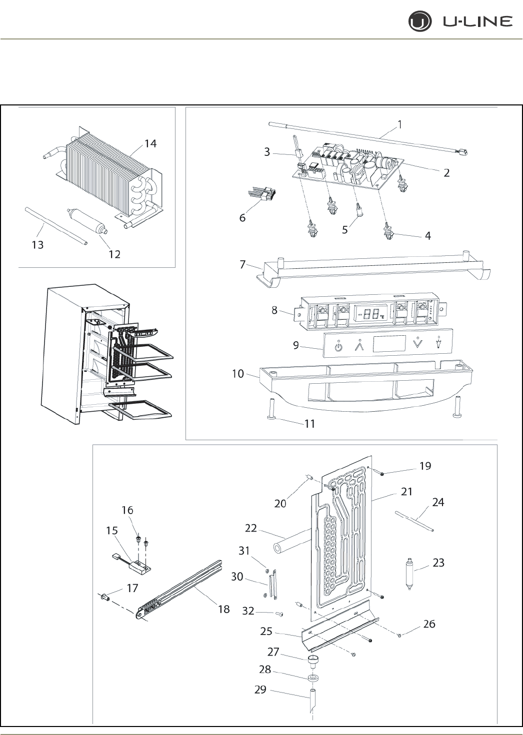
4-20
Section 4 - Parts
2115R (2 of 2)

4-21
Section 4 - Parts
2115R (2 of 2)
Item Part No. Part No. Part No. Description
Black White Stainless Steel
1 68092 68092 68092 Thermistor, quick connect white
2 68072-S 68072-S 68072-S Circuit Board Assembly
3 68080 68080 68080 Switch jumper (included with 68072-S)
4 41992 41992 41992 Support, circuit board (included with 68072-S)
5 41993 41993 41993 Support, circuit board (included with 68072-S)
6 2950-01 2950-01 2950-01 Wire connector, 12-pin
7 26086 26086 26086 Liner, baseplate
8 68074 68074 68074 Display Assembly, Echelon
9 68059-01 68059-01 68059-01 Display glass, Echelon control
10 26089 26089 26089 Housing, display
11 42162 42162 42162 Screw, 8-18 x .75, plastite
12 2694 2694 2694 Dryer (included with 2303-02-S)
13 2800 2800 2800 Process tube (included with 2303-02-S)
14 2303-02-S 2303-02-S 2303-02-S Condenser Assembly
15 66010 66010 66010 Reed Switch
16 20026 20026 20026 Screw, reed switch
17 31434-1 31434-1 31434-1 Rivet, thermistor cover
18 26091 26091 26091 Cover, thermistor
19 41855 41855 41855 Screw, Evaporator
20 31213 31213 31213 Spacer, Evaporator
21 2878-01-S 2878-01-S 2878-01-S Evaporator Assembly
22 31154 31154 31154 Armaflex (included with 27878-01-S)
23 2694 2694 2694 Dryer (included with 27878-01-S)
24 2800 2800 2800 Process tube (included with 27878-01-S)
25 31391-4 31391-4 31391-4 Drain trough
26 21012-WHT 21012-WHT 21012-WHT Rivet, white
27 11508 11508 11508 Drain cup
28 31578 31578 31578 Washer, drain tube
29 31726 31726 31726 Formed drain tube
30 11835 11835 11835 Clamp, thermistor
31 41158 41158 41158 Nut
32 41156 41156 41156 Screw
Not N/A N/A 12091 Bushing, top pivot post
Shown
Not N/A N/A 14159-01 Commercial handle (SS accessory only)
Shown

4-22
Section 4 - Parts
2175WC/2175WCOL/2175WCOL2 (1 OF 2)
23
24
31
30
29
25
27 26
34
32
3333
28 7
813
12
11
10
35
36
41
40
22
20 21
13
9
12
1, 2
654
19
39
3837
7
8
6
7
8
37
38
3
18
17
16 15

4-23
Section 4 - Parts
Item Part No. Part No. Part No. Description
Black White Stainless Steel
1 80-17057-01 80-17057-03 Door Assembly, RH
2 N/A 80-17057-13 Door Assembly, LH
3 80-17081-02 N/A Overlay Door (Model U-2175WCOL-00)
80-17104-11 N/A Overlay Door (Model U-2175WCOL2-00)
4 26088-4-BLK N/A Handle Assembly
5 42173-BLK N/A Hole plug (included with handle assembly)
6 12094-01 12094-02 Gasket, door
7 11994-BLK-S 11994-BLK-S Pivot plate
8 42161-ZP 42161-ZP Screw, pivot plate
9 11995-S-BLK 11995-S-SS Hinge Assembly, top
10 11996-S-BLK 11996-S-SS Hinge Assembly, bottom
11 31673-S 31673-S Door Closer Assembly
12 42101-BLK 42101-SS Screw, hinge (included with hinge assembly)
13 42096 42096 Pivot post (included with hinge assembly)
14 42174 N/A Screw, handle
15 80-29010-01 80-29010-03 Grille
16 20033-BLK 20033-ZP Screw (included with grille)
17 2945 2945 Jumper wire, power cord
18 16002 16002 Hinge Backing Plate Assembly
19 N/A 14160-01 Towel Bar Handle Assembly
20 11969 11969 Back panel
21 41342 41342 Screw, back panel
42125 42125 Hole Cover, perforated
22 2891-01 2891-01 Light Socket Assembly
23 41319 41319 Foot, leveler
24 2938-2 2938-2 Power cord
25 5400-S 5400-S Compressor, EMY130HER
26 2800 2800 Process tube (included with 5400-S)
27 2694 2694 Dryer (included with 5400-S)
28 31021 31021 Grommet (included with 5400-S)
29 5411 5411 Overload (included with 5400-S)
30 5412 5412 Relay (included with 5400-S)
31 5400-CAP 5400-CAP Cover (included with 5400-S)
32 5263-S 5263-S Fan motor, condenser
33 5188 5188 Fan blade, condenser
34 41787 41787 Nut (included with 5263-S)
35 31550-1-S 31550-1-S Drain Pan Assembly
36 31664 31664 Tape (included with #35)
37 66016 66016 Magnet
38 20050 20050 Screw, magnet
39 66019 66019 Spacer, nylon
40 11859 11859 Lens, light housing
41 31317 31317 Light bulb, 10W, 120V
Not N/A 14159-01 Commercial handle (SS accessory only)
Shown
2175WC/2175WCOL/2175WCOL2 (1 OF 2)
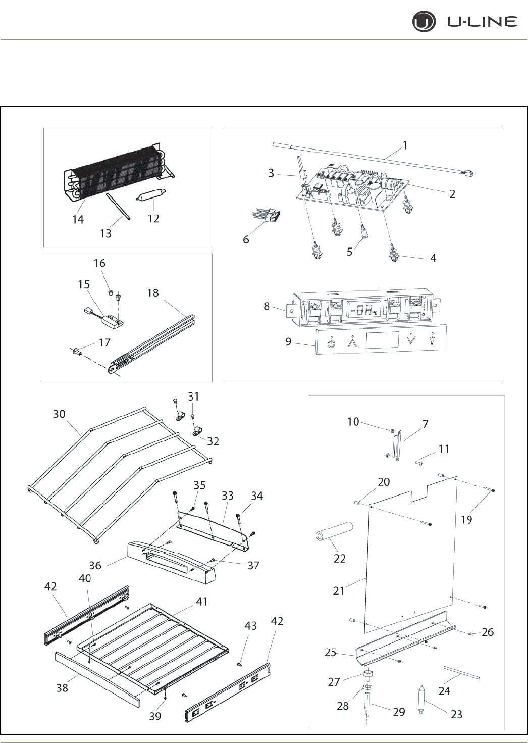
4-24
Section 4 - Parts
2175WC/2175WCOL /2175WCOL2(2 OF 2)

4-25
Section 4 - Parts
Item Part No. Part No. Description
Black Stainless Steel
1 68092 68092 Thermistor, quick connect white
2 68072-S 68072-S Circuit Board Assembly
3 68080 68080 Switch jumper (included with 68072-S)
4 41992 41992 Support, circuit board (included with 68072-S)
5 41993 41993 Support, circuit board (included with 68072-S)
6 2950-1 2950-1 Wire connector, 12-pin
7 11835 11835 Clamp, thermistor
8 68074 68074 Display Assembly, Echelon
9 68059-01 68059-01 Display glass, Echelon control
10 41158 41158 Nut
11 41156-02 41156-02 Screw, black
12 2694 2694 Dryer (included with 2303-S)
13 2800 2800 Process tube (included with 2303-S)
14 2303-S 2303-S Condenser Assembly
15 66010 66010 Reed Switch
16 20026 20026 Screw, reed switch
17 31434-2 31434-2 Rivet, thermistor cover
18 26091-02 26091-02 Cover, thermistor, black
19 41855-02 41855-02 Screw, Evaporator
20 31213 31213 Spacer, Evaporator
21 2186-02-S 2186-02-S Evaporator Assembly, black
22 31154 31154 Armaflex (included with 2186-02-SS)
23 2694 2694 Dryer (included with 2186-02-S)
24 2800 2800 Process tube (included with 2186-02-S)
25 31391-7 31391-7 Drain trough
26 21012-BLK 21012-BLK Rivet, black
27 11508-02 11508-02 Drain cup
28 31578-02 31578-02 Washer, drain tube
29 31726 31726 Formed drain tube
30 18048 18048 Display Rack
31 31434-2 31434-2 Rivet, large, black
32 31648-02 31648-02 Clamp, black
33 14135-01 14135-01 Mounting bracket, angle, display
34 41405 41405 Screw
35 42106 42106 Screw
36 39006-01 39006-01 Wood Front Housing
37 42122 42122 Screw
38 39004-01 39004-01 Wood Front
39 4816 4816 Screw
40 42106 42106 Screw, wood
41 18066-Vinyl 18066-Vinyl Wine Rack
42 23027-03 23027-03 Slide Assembly (set of two)
43 4816 4816 Screw (included with 23027-03)
2175WC/2175WCOL /2175WCOL2(2 of 2)
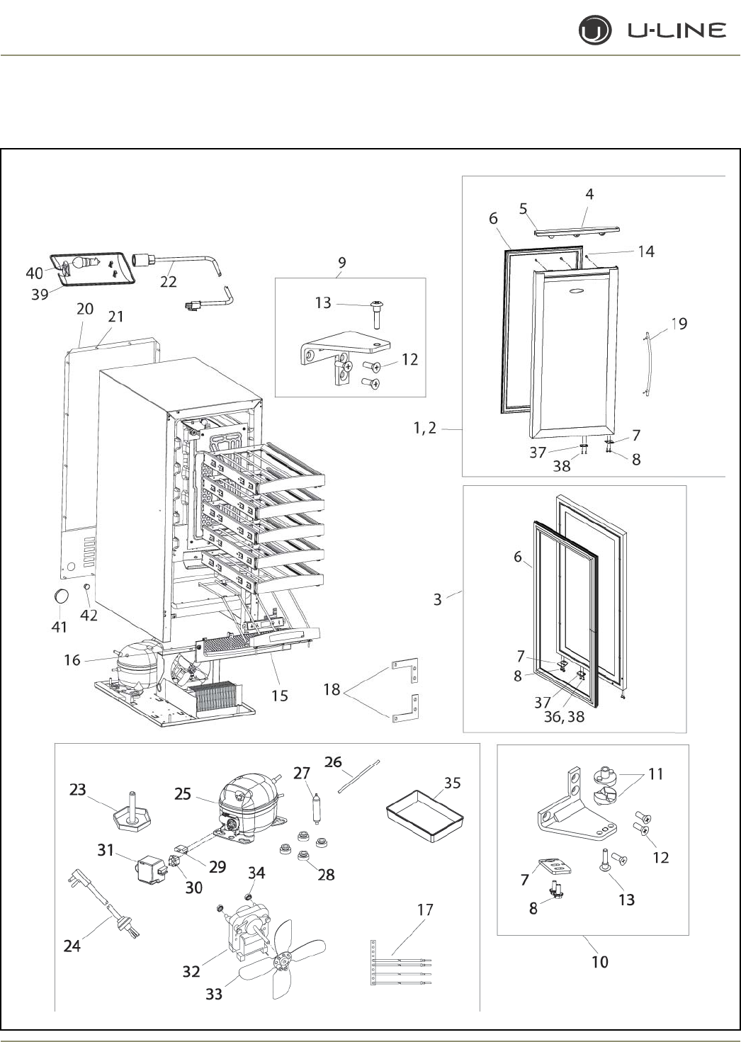
4-26
Section 4 - Parts
2115WC/2115WCOL/2115WCOL2 (1OF2)

4-27
Section 4 - Parts
2115WC/2115WCOL/2115WCOL2 (1 of 2)
Item Part No. Part No. Description
Black Stainless Steel
1 80-17065-01 80-17065-03 Door Assembly, RH
2 N/A 80-17065-13 Door Assembly, LH
3 80-17081-01 N/A Overlay Door (Model U-2115WCOL-00)
80-17104-12 N/A Overlay Door (Model U-2115WCOL2-00)
4 26088-6-BLK N/A Handle Assembly
5 42173-BLK N/A Hole plug (included with handle assembly)
6 31493-8-BLK 31496-8-GRY Gasket, door
7 11994-BLK-S 11994-BLK-S Pivot plate
8 42161-ZP 42161-ZP Screw, pivot plate
9 11995-S-BLK 11995-S-SS Hinge Assembly, top
10 11996-S-BLK 11996-S-SS Hinge Assembly, bottom
11 31673-S 31673-S Door Closer Assembly
12 42101-BLK 42101-SS Screw, hinge (included with hinge assembly)
13 42096 42096 Pivot post (included with hinge assembly)
14 42174 N/A Screw, handle
15 80-29012-01 80-29012-03 Grille
16 20033-BLK 20033-ZP Screw (included with grille)
17 2945 2945 Jumper wire, power cord
18 16002 16002 Hinge Backing Plate Assembly
19 N/A 14160-01 Towel Bar Handle Assembly
20 11964-01 11964-01 Back panel
21 41342 41342 Screw, back panel
22 2891-01 2891-01 Light Socket Assembly
23 41319 41319 Foot, leveler
24 2938-2 2938-2 Power cord
25 5400-S 5400-S Compressor, EMY130HER
26 2800 2800 Process tube (included with 5400-S)
27 2694 2694 Dryer (included with 5400-S)
28 31021 31021 Grommet (included with 5400-S)
29 5411 5411 Overload (included with 5400-S)
30 5412 5412 Relay (included with 5400-S)
31 5400-CAP 5400-CAP Cover (included with 5400-S)
32 5263-S 5263-S Fan motor, condenser
33 5188 5188 Fan blade, condenser
34 41787 41787 Nut (included with 5263-S)
35 31385 13185 Drain Pan
36 66019 66019 Spacer, magnet
37 66016 66016 Magnet
38 20050 20050 Screw, magnet
39 11859 11859 Lens, light housing
40 31317 31317 Light bulb, 10W, 120V
41 42125 42125 Hole cover, perforated
42 42126 42126 Hole cover, solid
Not N/A 14159-01 Commercial handle (SS accessory only)
Shown
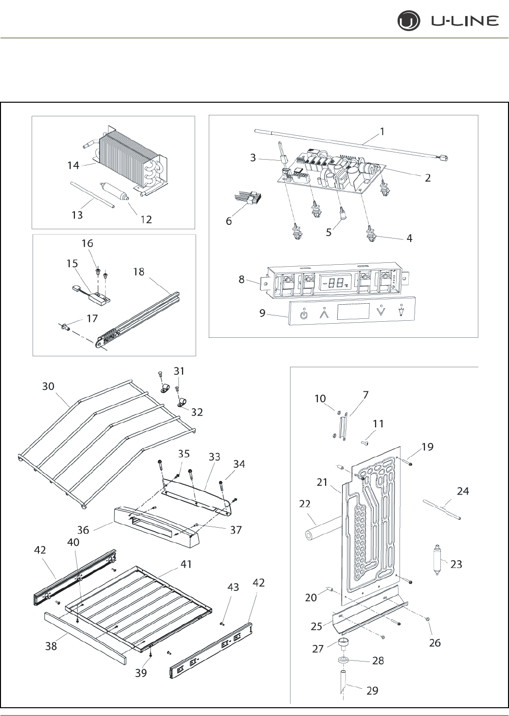
4-28
Section 4 - Parts
2115WC/2115WCOL/2115WCOL2 (2 OF 2)

4-29
Section 4 - Parts
Item Part No. Part No. Description
Black Stainless Steel
1 68092 68092 Thermistor, quick connect white
2 68072-S 68072-S Circuit Board Assembly
3 68080 68080 Switch jumper (included with 68072-S)
4 41992 41992 Support, circuit board (included with 68072-S)
5 41993 41993 Support, circuit board (included with 68072-S)
6 2950-1 2950-1 Wire connector, 12-pin
7 11835 11835 Clamp, thermistor
8 68074 68074 Display Assembly, Echelon
9 68059-01 68059-01 Display glass, Echelon control
10 41158 41158 Nut
11 41156-02 41156-02 Screw, black
12 2694 2694 Dryer (included with 2303-S)
13 2800 2800 Process tube (included with 2303-S)
14 2303-02-S 2303-02-S Condenser Assembly
15 66010 66010 Reed Switch
16 20026 20026 Screw, reed switch
17 31434-2 31434-2 Rivet, thermistor cover
18 26091-02 26091-02 Cover, thermistor
19 41855-02 41855-02 Screw, Evaporator
20 31213 31213 Spacer, Evaporator
21 2649-02-S 2649-02-S Evaporator Assembly, black
22 31154 31154 Armaflex (included with 2649-02-S)
23 2694 2694 Dryer (included with 2649-02-S)
24 2800 2800 Process tube (included with 2649-02-S)
25 31391-8 31391-8 Drain trough
26 21012-BLK 21012-BLK Rivet, black
27 11508-02 11508-02 Drain cup
28 31578-02 31578-02 Washer, drain tube
29 31726 31726 Formed drain tube
30 18052 18052 Display Rack
31 31434-2 31434-2 Rivet, large, black
32 31648-02 31648-02 Clamp, black
33 14135-02 14135-02 Mounting bracket, angle, display
34 41405 41405 Screw
35 42106 42106 Screw
36 39006-02 39006-02 Wood Front Housing
37 42122 42122 Screw
38 39004-02 39004-02 Wood Front
39 4816 4816 Screw
40 42106 42106 Screw, wood
41 18067-Vinyl 18067-Vinyl Wine Rack
42 23027-03 23027-03 Slide (set of two)
2115WC/2115WCOL/2115WCOL2 (2 of 2)
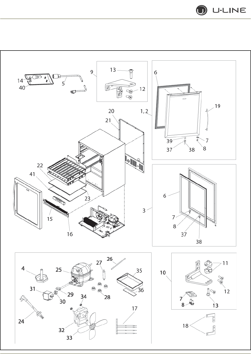
4-30
Section 4 - Parts
43 4816 4816 Screw (included with 23027-03)
2175BEV/2175BEVOL/2175BEVOL2 (1 OF 2)

4-31
Section 4 - Parts
Item Part No. Part No. Description
Overlay Door Stainless Steel
1 N/A 80-17094-03 Door Assembly, RH
2 N/A 80-17094-13 Door Assembly, LH
3 80-17094-01 N/A Overlay Door (Model U-2175BEVOL-00)
80-17104-11 N/A Overlay Door (Model U-2175BEVOL2-00)
4 41319 41319 Foot, leveler
5 2891-01 2891-01 Light Socket Assembly
6 12094-01 12094-02 Gasket, door
7 11994-BLK-S 11994-BLK-S Pivot plate
8 42161-ZP 42161-ZP Screw, pivot plate
9 11995-S-BLK 11995-S-SS Hinge Assembly, top
10 11996-S-BLK 11996-S-SS Hinge Assembly, bottom
11 31673-S 31673-S Door Closer Assembly
12 42101-BLK 42101-SS Screw, hinge (included with hinge assembly)
13 42096 42096 Pivot post (included with hinge assembly)
14 31317 31317 Light bulb, 10W, 120V
15 80-29010-01 80-29010-03 Grille
16 20033-BLK 20033-ZP Screw (included with grille)
17 2945 2945 Jumper wire, power cord
18 16002 16002 Hinge Backing Plate Assembly
19 N/A 14160-01 Towel Bar Handle Assembly
20 11969 11969 Back panel
21 41342 41342 Screw, back panel
22 40010-12 40010-12 Glass shelf
23 25032-7 25032-7 Edge trim, rear
24 2938-2 2938-2 Power cord
25 5400-S 5400-S Compressor, EMY130HER
26 2800 2800 Process tube (included with 5400-S)
27 2694 2694 Dryer (included with 5400-S)
28 31021 31021 Grommet (included with 5400-S)
29 5411 5411 Overload (included with 5400-S)
30 5412 5412 Relay (included with 5400-S)
31 5400-CAP 5400-CAP Cover (included with 5400-S)
32 5263-S 5263-S Fan motor, condenser
33 5188 5188 Fan blade, condenser
34 41787 41787 Nut (included with 5263-S)
35 31550-1-S 31550-1-S Drain Pan Assembly
36 31664 31664 Tape (included with #35)
37 66016 66016 Magnet
38 20050 20050 Screw, magnet
39 66019 66019 Spacer, nylon
40 11859 11859 Lens, light housing
41 31443-11 31443-11 Edge trim, front
Not N/A 14159-01 Commercial handle (SS accessory only)
Shown
2175BEV/2175BEVOL/2175BEVOL2 (1 of 2)
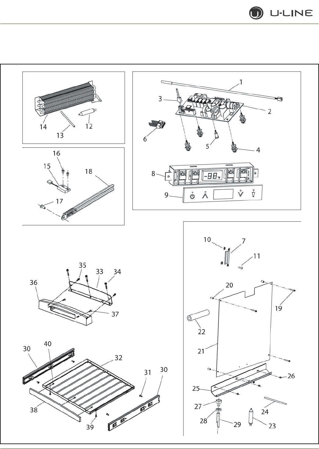
4-32
Section 4 - Parts
2175BEV/2175BEVOL/2175BEVOL2 (2 OF 2)

4-33
Section 4 - Parts
Item Part No. Part No. Description
Black Stainless Steel
1 68092 68092 Thermistor, quick connect white
2 68072-S 68072-S Circuit Board Assembly
3 68080 68080 Switch jumper (included with 68072-S)
4 41992 41992 Support, circuit board (included with 68072-S)
5 41993 41993 Support, circuit board (included with 68072-S)
6 2950-1 2950-1 Wire connector, 12-pin
7 11835 11835 Clamp, thermistor
8 68074 68074 Display Assembly, Echelon
9 68059-01 68059-01 Display glass, Echelon control
10 41158 41158 Nut
11 41156-02 41156-02 Screw
12 2694 2694 Dryer (included with 2303-S)
13 2800 2800 Process tube (included with 2303-S)
14 2303-S 2303-S Condenser Assembly
15 66010 66010 Reed Switch
16 20026 20026 Screw, reed switch
17 31434-2 31434-2 Rivet, thermistor cover
18 26091-02 26091-02 Cover, thermistor
19 41855-02 41855-02 Screw, Evaporator
20 31213 31213 Spacer, Evaporator
21 2186-02-S 2186-02-S Evaporator Assembly, black
22 31154 31154 Armaflex (included with 2186-02-SS)
23 2694 2694 Dryer (included with 2186-02-S)
24 2800 2800 Process tube (included with 2186-02-S)
25 31391-7 31391-7 Drain trough
26 21012-BLK 21012-BLK Rivet, black
27 11508-02 11508-02 Drain cup
28 31578-02 31578-02 Washer, drain tube
29 31726 31726 Formed drain tube
30 23027-03 23027-03 Slide Assembly (set of 2)
31 4816 4816 Screw (included with 23027-03)
32 18066-Vinyl 18066-Vinyl Wine Rack
33 14135-02 14135-02 Mounting bracket, angle, display
34 41405 41405 Screw
35 42106 42106 Screw
36 39006-02 39006-02 Wood Front Housing
37 42122 42122 Screw
38 39004-01 39004-01 Wood Front
39 4816 4816 Screw
40 42106 42106 Screw, wood
2175BEV/2175BEVOL/2175BEVOL2 (2 of 2)
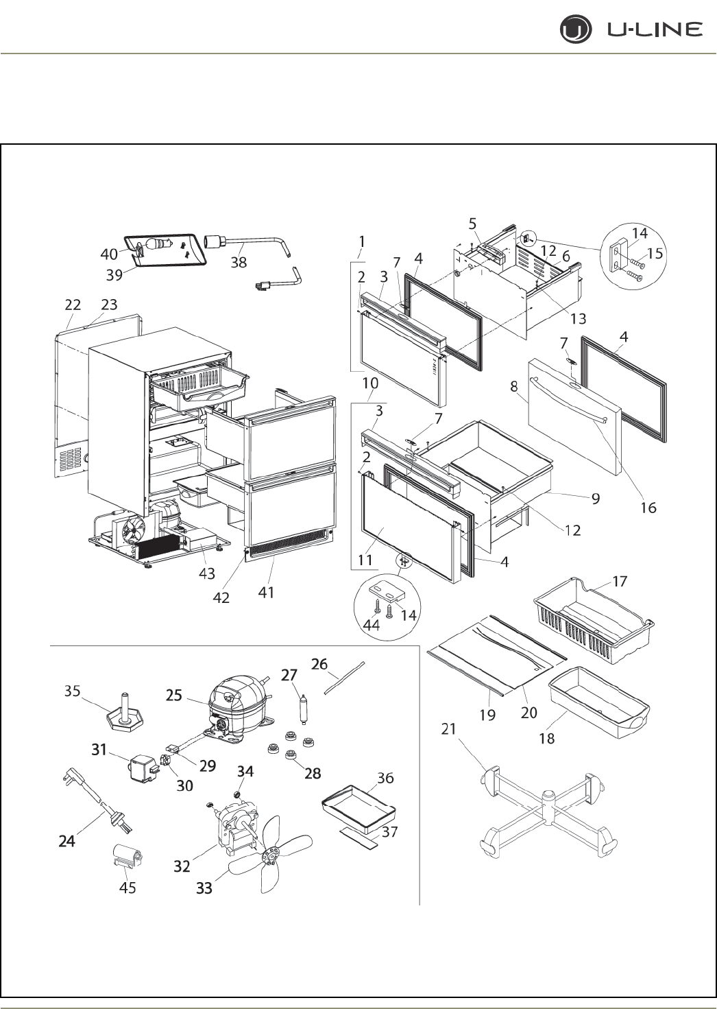
4-34
Section 4 - Parts
2175DWRR/2275DWRR (1 OF 2)

4-35
Section 4 - Parts
Item Part No. Part No. Description
Black Stainless Steel
1 2175DWR-TOP-BLK N/A Drawer Front Assembly
2 41604 N/A Screw, handle
3 26070-05-S N/A Handle, overlay
4 12094-07 12094-08 Gasket, door
5 26094 26094 Housing, display
6 14138-02 14138-02 Drawer, no front, top
7 23025 23025 Nameplate
8 N/A 11939-05-S Stainless steel wrap only (includes handle)
9 14008-S 14008-S Drawer, no front, bottom
10 2175DWR-BTM-BLK N/A Drawer Front Assembly, bottom
11 11933-18-BLK N/A Front panel only
12 41156 41156 Screw
13 41965 41965 Spacer, nylon
14 66016 66016 Magnet
15 41259 41259 Rivet, magnet
16 N/A 14160-05 Towel Bar Handle Assembly
17 26000 26000 Crisper, top
18 26001 26001 Crisper, bottom
19 31443-7 31443-7 Trim, front edge
20 40000-02 40000-02 Crisper Shelf
21 80-48001-00 80-48001-00 Drawer Organizer Assembly
22 11969 11969 Back panel
23 41342 41342 Screw, back panel
24 2955-2 2955-2 Power cord
25 70077-S 70077-S Compressor
26 2800 2800 Process tube (included with 70077-S)
27 2694 2694 Dryer (included with 70077-S)
28 31021 31021 Grommet (included with 70077-S)
29 71009 71009 Overload (included with 70077-S)
30 71010 71010 Relay (included with 70077-S)
31 70077-CAP 70077-CAP Cover (included with 70077-S)
32 5263-S 5263-S Fan motor, condenser
33 5188 5188 Fan blade, condenser
34 41787 41787 Nut (included with 5263-S)
35 41319 41319 Foot, leveler
36 31550-1-S 31550-1-S Drain Pan Assembly
37 31664 31664 Tape (included with #36)
38 2891-01 2891-01 Light Socket Assembly
39 11859 11859 Lens, light housing
40 31317 31317 Light bulb, 10W, 120V
41 80-29010-01 80-29010-03 Grille Assembly
42 20033-BLK 20033-ZP Screw (included with grille)
43 14147-01 14107-01 Splash guard (included with 70077-S)
44 20050 20050 Screw, magnet
45 71008 71008 Capacitor (included with 70077-S)
2175DWRR/2275DWRR (1 of 2)
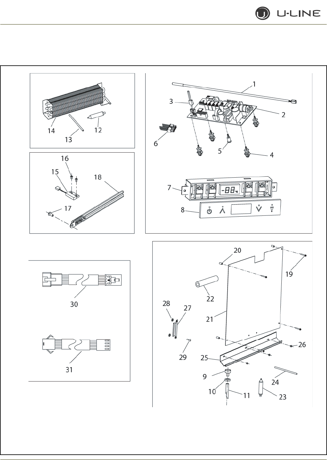
4-36
Section 4 - Parts
2175DWRR/2275DWRR (2 of 2)

4-37
Section 4 - Parts
2175DWRR/2275DWRR (2 of 2)
Item Part No. Part No. Description
Black Stainless Steel
1 68092 68092 Thermistor, quick connect white
2 68072-S 68072-S Circuit Board Assembly
3 68080 68080 Switch jumper (included with 68072-S)
4 41992 41992 Support, circuit board (included with 68072-S)
5 41993 41993 Support, circuit board (included with 68072-S)
6 2950-01 2950-01 Wire connector, 12-pin
7 68074 68074 Display Assembly, Echelon
8 68059-01 68059-01 Display glass, Echelon control
9 11508 11508 Drain cup (white)
11508-02 11508-02 Drain cup (black)
10 31578 31578 Washer, drain tube (white)
31578-02 31578-02 Washer, drain tube (black)
11 31726 31726 Formed drain tube
12 2694 2694 Dryer (included with 2303-S)
13 2800 2800 Process tube (included with 2303-S)
14 2303-S 2303-S Condenser Assembly
15 66010 66010 Reed Switch
16 20026 20026 Screw, reed switch
17 31434-1 31434-1 Rivet, thermistor cover (white)
31434-2 31434-2 Rivet, thermistor cover (black)
18 26091 26091 Cover, thermistor (white)
26091-02 26091-02 Cover, thermistor (black)
19 41855 41855 Screw, evaporator (SS)
41855-02 41855-02 Screw, evaporator (black)
20 31213 31213 Spacer, evaporator
21 2333-S 2333-S Evaporator Assembly, (white)
2333-02-S 2333-02-S Evaporator Assembly, (black)
22 31154 31154 Armaflex (included with 2333-02-SS)
23 2694 2694 Dryer (included with 2333-02-S)
24 2800 2800 Process tube (included with 2333-02-S)
25 31391-6 31391-6 Drain trough (white)
31391-7 31391-7 Drain trough (black)
26 21012-WHT 21012-WHT Rivet, (white)
21012-BLK 21012-BLK Rivet, (black)
27 11835 11835 Clamp, thermistor
28 41158 41158 Nut
29 41156 41156 Screw (SS)
41156-02 41156-02 Screw (black)
30 2953 2953 Wire harness (from display to plug)
31 2952 2952 Wire harness (base to plug)
Not 26070-01-S N/A Full handle
Shown
Not N/A 14159-05 Commerical handle (SS accesory only)
Shown
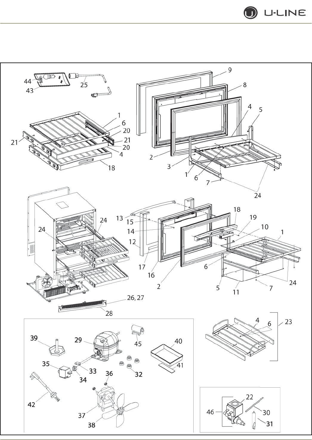
4-38
Section 4 - Parts
2275DWRWS/2275DWRWOL (1 OF 2)

4-39
Section 4 - Parts
Item Part No. Description
1 18066-Vinyl Wine Rack Assembly
2 12094-08-GREY Gasket, drawer, grey
12094-07-BLK Gasket, drawer, black
3 14016 Front, top drawer
4 39004-03 Wood front, top drawer
5 41729 Pop rivet, stainless steel
6 42106 Screw, wood
7 42175 Pop rivet
8 26018-02 Glass front, top drawer
9 14030-03 Stainless steel wrap, top
10 2953 Main wire to harness
11 14017 Tub, bottom drawer
12 14030-04 Stainless steel wrap, bottom
13 14160-05 Towel Bar Handle Assembly
14 20046 Screw
15 23015 Washer, felt
16 26023 Glass front, drawer
17 35009 Transfer tape
18 39006-03 Wood front display,
bottom drawer
19 42122 Screw
20 4816 Screw
21 23027-03 Slide Assembly (set of 2)
22 73002-2 Coil (included with 73002-S)
23 80-48005-00 Wine Caddy Assembly
(includes items 4 & 6)
24 80-47001-00 Drawer Slide Assembly
(set of 2)
25 2891-01 Light Socket Assembly
26 80-29010-01 Grille Assembly, black
Item Part No. Description
27 80-29010-03 Grille Assembly, SS
28 20033-ZP Screw (included with grille)
29 70077-S Compressor Assembly
30 2800 Process tube
(included with 70077-S
31 2694 Dryer (included with 70077-S)
32 31021 Grommet
(included with 70077-S)
33 71009 Overload
(included with 70077-S)
34 71010 Relay (included with 70077-S)
35 70077-CAP Cap (included with 70077-S)
36 41787 Nut (included with 5263-S)
37 5263-S Fan motor, condenser
38 5188 Fan blade
39 41319 Foot, leveler
40 31550-1-S Drain Pan Assembly
41 31664 Tape (included with #40))
42 2948 Power cord
43 11859 Lens, light housing
44 31317 Light bulb, 10W, 120V
45 71013 Capacitor
(included with 70077-S)
46 73002-S Refrigerator valve
Not 66018-01 Light switch
Shown
Not 80-50002-00 Overlay Bracket Assembly
Shown
Not 14159-05 Commercial handle
Shown (SS accessory only)
2275DWRWS/2275DWRWOL (1 of 2)
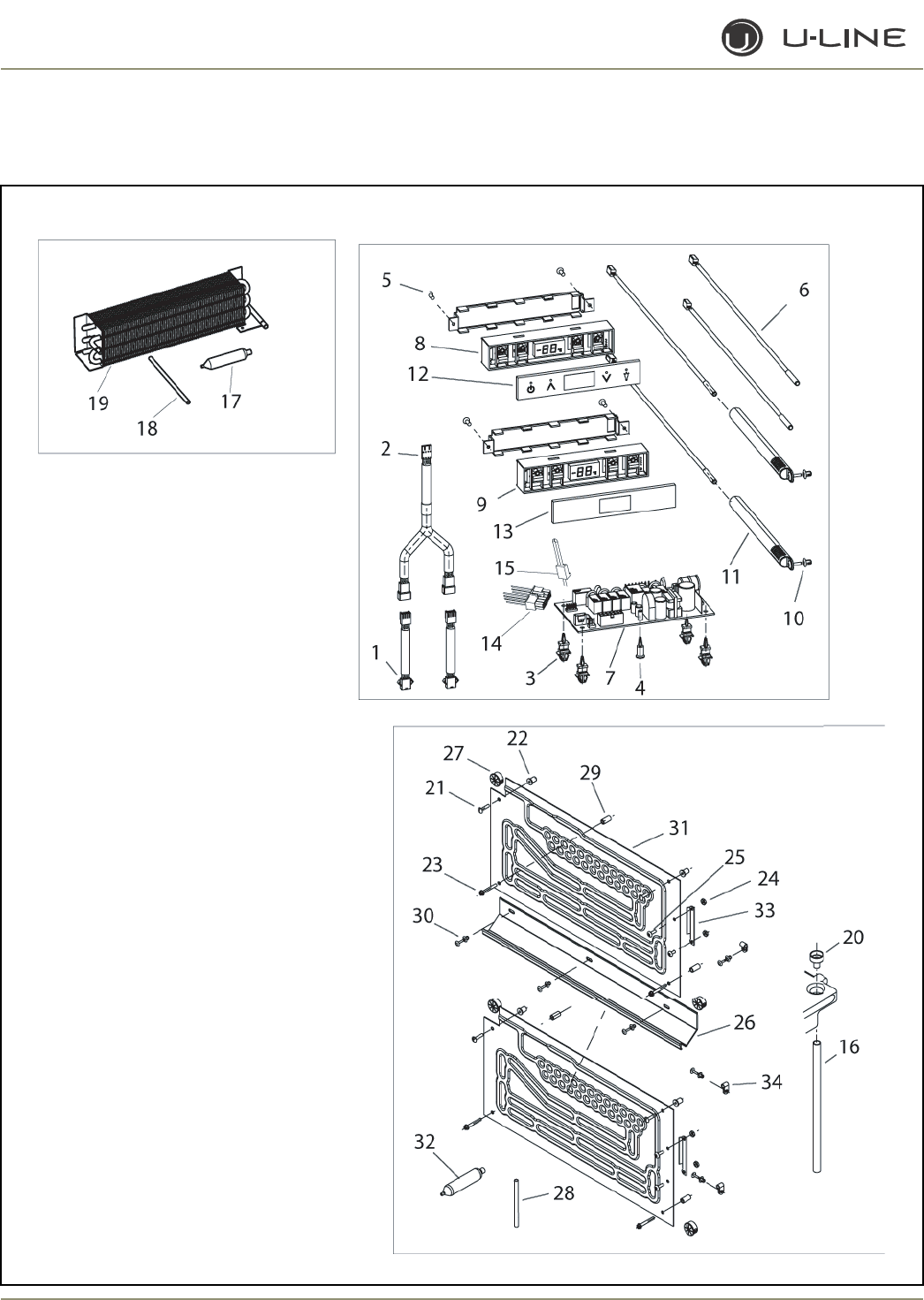
4-40
Section 4 - Parts
2275DWRWS/2275DWRWOL (2 OF 2)

4-41
Section 4 - Parts
Item Part No. Description
1 2953 Main harness to plug
2 2959 Dual Harness
3 41992 Support, circuit board
(included with 68064)
4 41993 Support, center, circuit
(included with 68064)
5 42122 Screw, wood
6 68092 Thermistor Assembly
7 68084 Main Board
8 68085 Display Assembly, top drawer
9 68086 Display Assembly, bottom drawer
10 21012-BLK Rivet, black
11 26091-02 Sensor cover, black
12 68059-01 Display glass, top drawer
13 68083-01 Display glass, bottom drawer
14 2950-01 Wire connector, 12-pin
15 68080 Jumper switch
(included with 68084)
16 41967-4 Drain tube
Item Part No. Description
17 2694 Dryer (included with 2303-S)
18 2800 Process tube (included with 2303-S
19 2303-S Condenser Assembly
20 11508-02 Drain cup
21 41981 Screw, upper, evaporator
22 41979 Well nut
23 41855-02 Screw, lower, evaporator
24 41158 Nut
25 41156-02 Screw
26 31391-9 Drain trough, black
27 31386 Bushing, black
28 2800 Process tube
(included with 2649-02-S)
29 31213 Spacer
30 21012-BLK Rivet, black
31 2649-02-S Evaporator Assembly
32 2694 Dryer (included with #31)
33 11835 Clamp, control bulb
34 21009 Clamp, cable
Not 31154 Armaflex (included with #31)
Shown
2275DWRWS/2275DWRWOL (2 of 2)
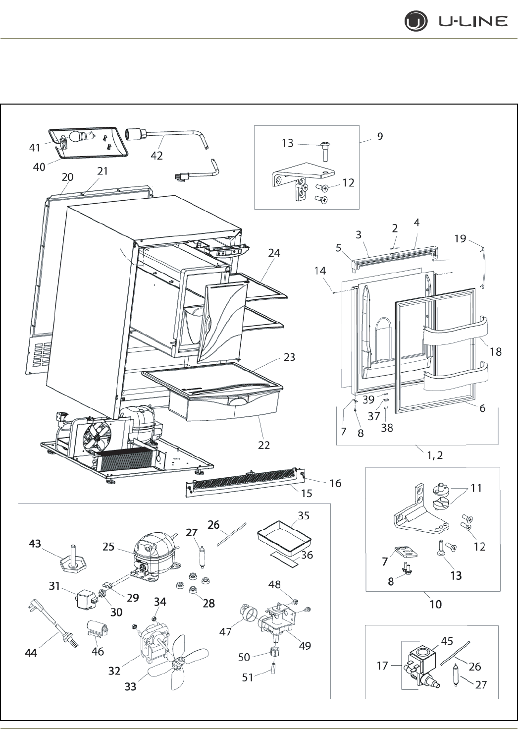
4-42
Section 4 - Parts
CO2175F (1 of 4)

4-43
Section 4 - Parts
Item Part No. Part No. Part No. Description
Black White Stainless Steel
1 80-17060-01 80-17060-02 80-17075-01 Door Assembly, RH
2 80-17060-01 80-17060-02 80-17075-02 Door Assembly, LH
3 23025 23025 23025 Nameplate
4 26070-01-S 26070-02-S N/A Handle Assembly
5 42173-BLK 42173-NAT N/A Hole plug (included with handle assembly)
6 12094-01 12094-03 12094-02 Gasket, door
7 11901-1-BLK-S 11901-1-BLK-S 11994-BLK-S Pivot plate
8 42161-ZP 42161-ZP 42161-ZP Screw, pivot plate
9 11898-S-BLK 11898-S-KIT 11995-S-SS Hinge Assembly, top
10 11899-S-BLK 11899-S-KIT 11996-S-SS Hinge Assembly, bottom
11 31673-S 31673-S 31673-S Door Closer Assembly
12 42101-BLK 42101-ZP 42101-SS Screw, hinge (included with hinge assembly)
13 42096 42096 42096 Pivot post (included with hinge assembly)
14 41604 41725 N/A Screw, handle (included with handle assembly)
15 80-29010-01 80-29010-02 80-29010-03 Grille
16 20033-BLK 20033-ZP 20033-ZP Screw (included with grille)
17 73002-FFS 73002-FFS 73002-FFS Danfoss Hot Gas Valve Assembly
18 31686 31686 31686 Door Shelf
19 N/A N/A 14160-01 Towel Bar Handle Assembly
20 11969 11969 11969 Back panel
21 41342 41342 41342 Screw, back panel
22 31685 31685 31685 Crisper drawer
23 31689 31689 31689 Crisper shelf
24 31696 31696 31696 Glass shelf
25 5408-FFS 5408-FFS 5408-FFS Compressor
26 2800 2800 2800 Process tube
27 2692 2692 2692 Dryer
28 31021 31021 31021 Grommet
29 71020 71020 71020 Overload
30 71021 71021 71021 Relay
CO2175F (1 of 4)
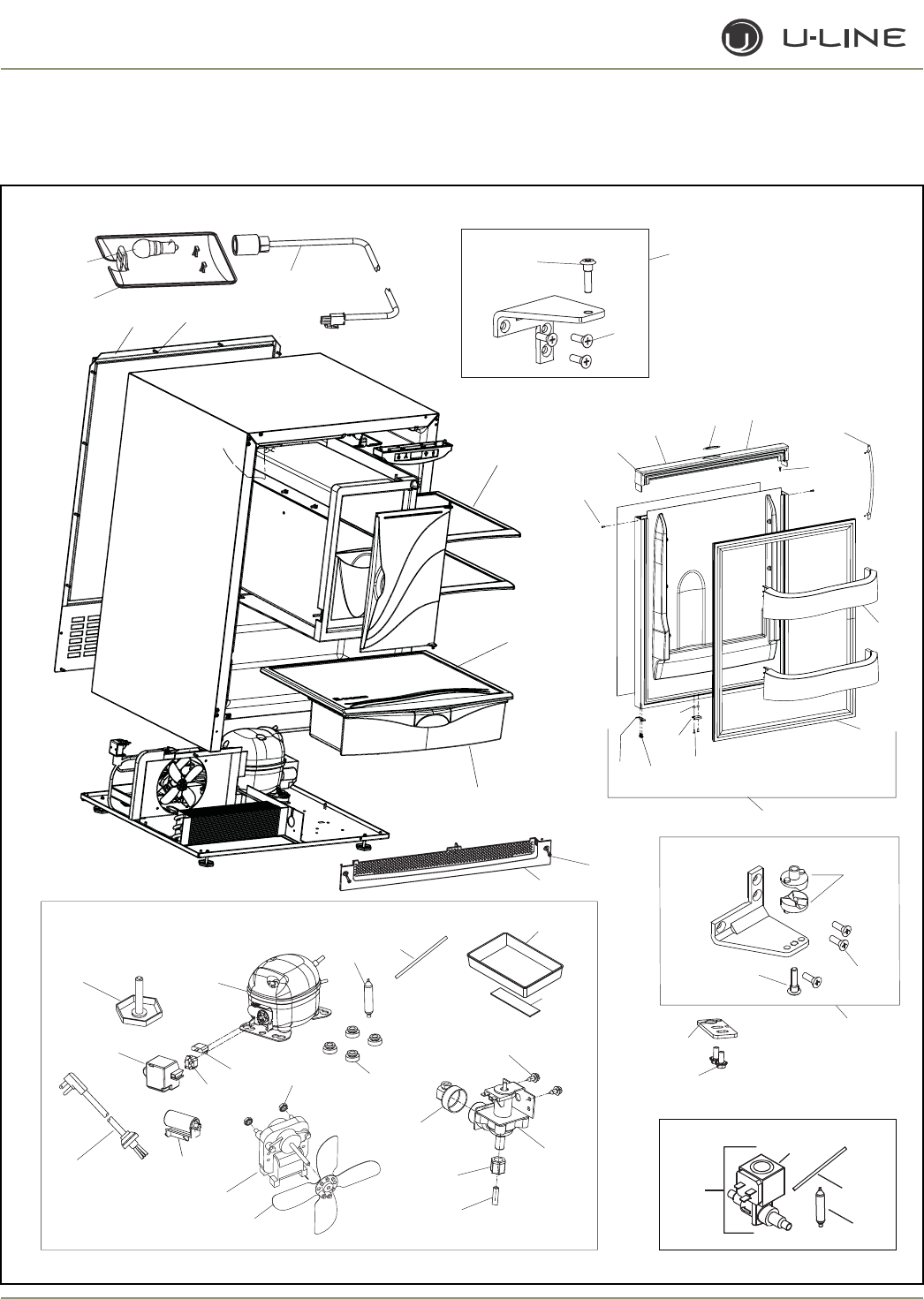
4-44
Section 4 - Parts
CO2175F (2 0f 4)
15
16
43
43
4444
3131
3030
2929
2525
2727 2626
3434
3232
3333
2828
7
8
13
13 12
11
1010
41
40
13 9
12
35
36
42
20 21
1, 2
23
22
24
14
32
19
6
78
39
37
38
18
5
4
46
51
50
47
49
48
17
45
26
27

4-45
Section 4 - Parts
Item Part No. Part No. Part No. Description
Black White Stainless Steel
31 5408-CAP 5408-CAP 5408-CAP Cover
32 5263-S 5263-S 5263-S Fan motor, condenser
33 5188 5188 5188 Fan blade, condenser
34 41787 41787 41787 Nut (included with 5263-S)
35 31550-1-S 31550-1-S 31550-1-S Drain Pan Assembly
36 31664 31664 31664 Tape
37 66016 66016 66016 Magnet
38 20050 20050 20050 Screw, magnet
39 66019 66019 66019 Spacer, nylon
40 11859 11859 11859 Lens, light housing
41 31317 31317 31317 Light bulb, 10W, 120V
42 2891-01 2891-01 2891-01 Light Socket Assembly
43 41319 41319 41319 Foot, leveler
44 2946 2946 2946 Power cord
45 73002-2 73002-2 73002-2 Solenoid only (included with #17)
46 71022 71022 71022 Capacitor
47 41826 41826 41826 Fitting, brass, 90°
48 42114 42114 42114 Screw
49 2552A 2552A 2552A Water valve
50 41254 41254 41254 Plastic Nut & Sleeve Assembly
51 404-FF 404-FF 404-FF Water Line Assembly
Not N/A N/A 14159-01 Commercial handle (SS accessory only)
Shown
CO2175F (2 of 4)
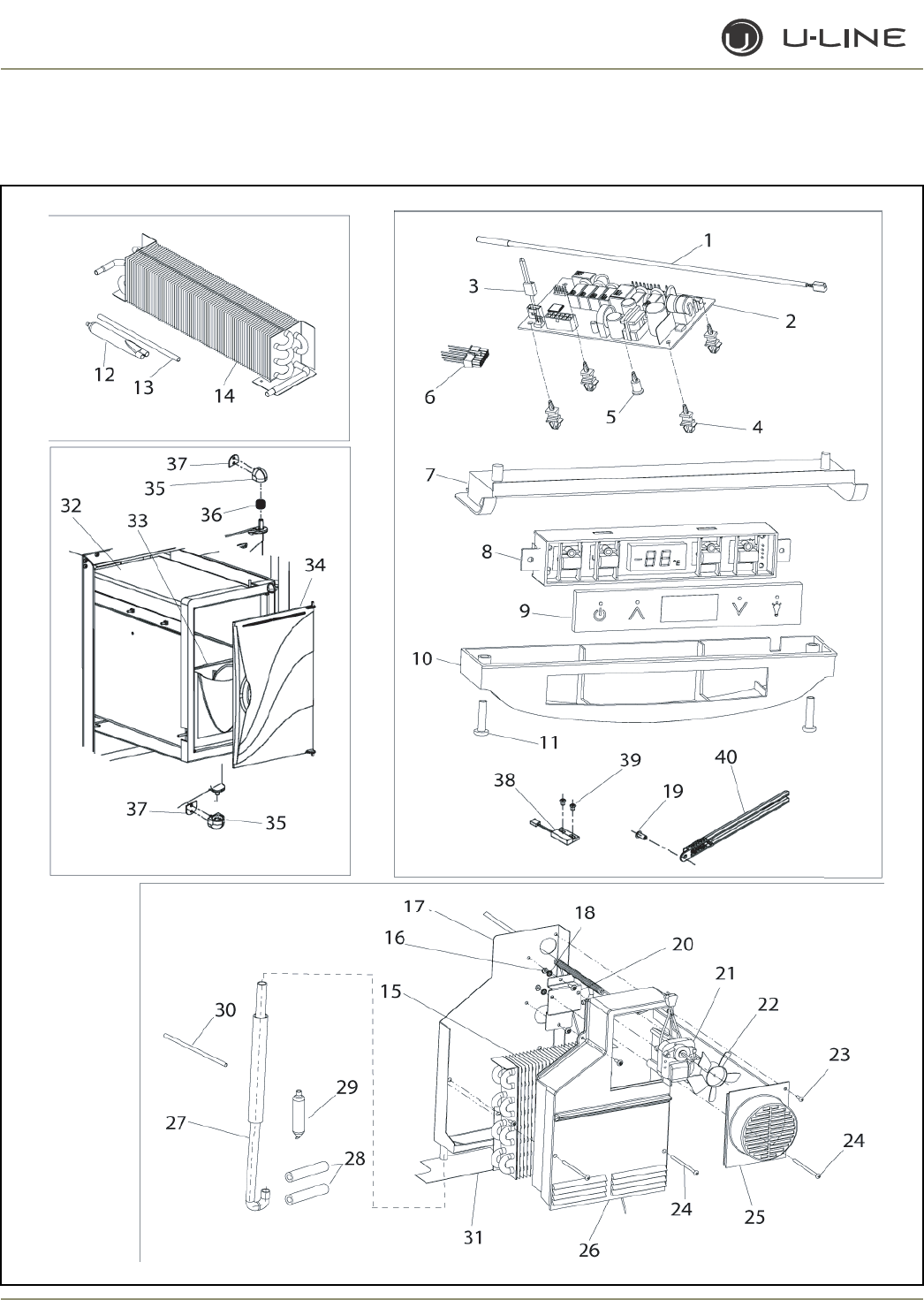
4-46
Section 4 - Parts
CO2175F (3 of 4)
4-47
Section 4 - Parts
Item Part No. Part No. Part No. Description
Black White Stainless Steel
1 68092 68092 68092 Thermistor, quick connect white
2 68072-S 68072-S 68072-S Circuit Board Assembly
3 68080 68080 68080 Switch jumper (included with 68072-S)
4 41992 41992 41992 Support, circuit board (included with 68072-S)
5 41993 41993 41993 Support, circuit board (included with 68072-S)
6 2950-02 2950-02 2950-02 Wire connector, 12-pin
7 26086 26086 26086 Liner, baseplate
8 68074 68074 68074 Display Assembly, Echelon
9 68059-01 68059-01 68059-01 Display glass, Echelon control
10 26089 26089 26089 Housing, display
11 42162 42162 42162 Screw, 8-18 x .75, plastite
12 2692 2692 2692 Dryer (included with 2303-FFS)
13 2800 2800 2800 Process tube (included with 2303-FFS)
14 2303-FFS 2303-FFS 2303-FFS Condenser Assembly
15 2334-FFS 2334-FFS 2334-FFS Evaporator Assembly (includs heat exchanger)
16 41158 41158 41158 Nut
17 2349 2349 2349 Drain Pan Assembly
18 41566 41566 41566 Washer
19 31434-1 31434-1 31434-1 Rivet
20 11855 11855 11855 Bracket, fan motor
21 5434 5434 5434 Fan motor, evaporator
22 31656 31656 31656 Fan blade, evaporator
23 42129 42129 42129 Screw
24 42099 42099 42099 Screw
25 11952 11952 11952 Fan cover, evaporator
26 11955 11955 11955 Cover, evaporator
27 31731 31731 31731 Drain tube
28 31410 31410 31410 Armaflex (included with #15)
29 2692 2692 2692 Dryer (included with #15)
30 2800 2800 2800 Process tube (included with #15)
31 66005 66005 66005 Heater, drain pan
32 80-35002-S 80-35002-S 80-35002-S Freezer Housing Assembly
33 26011 26011 26011 Ice Bucket
34 26069-S 26069-S 26069-S Freezer Door Assembly
(includes 35, 36 & 37)
35 12013-S 12013-S 12013-S Freezer Door Hinge Assembly
(includes top 36 & bottom 37)
36 42135 42135 42135 Spring, freezer door hinge
37 42157 42157 42157 Tape
38 66010 66010 66010 Reed Switch
39 20026 20026 20026 Screw
40 26091 26091 26091 Cover, thermistor
Not 31154 31154 31154 Armaflex (included with #15)
Shown
Not 35014 35014 35014 Tape, drain pan heater
Shown
CO2175F (3 of 4)
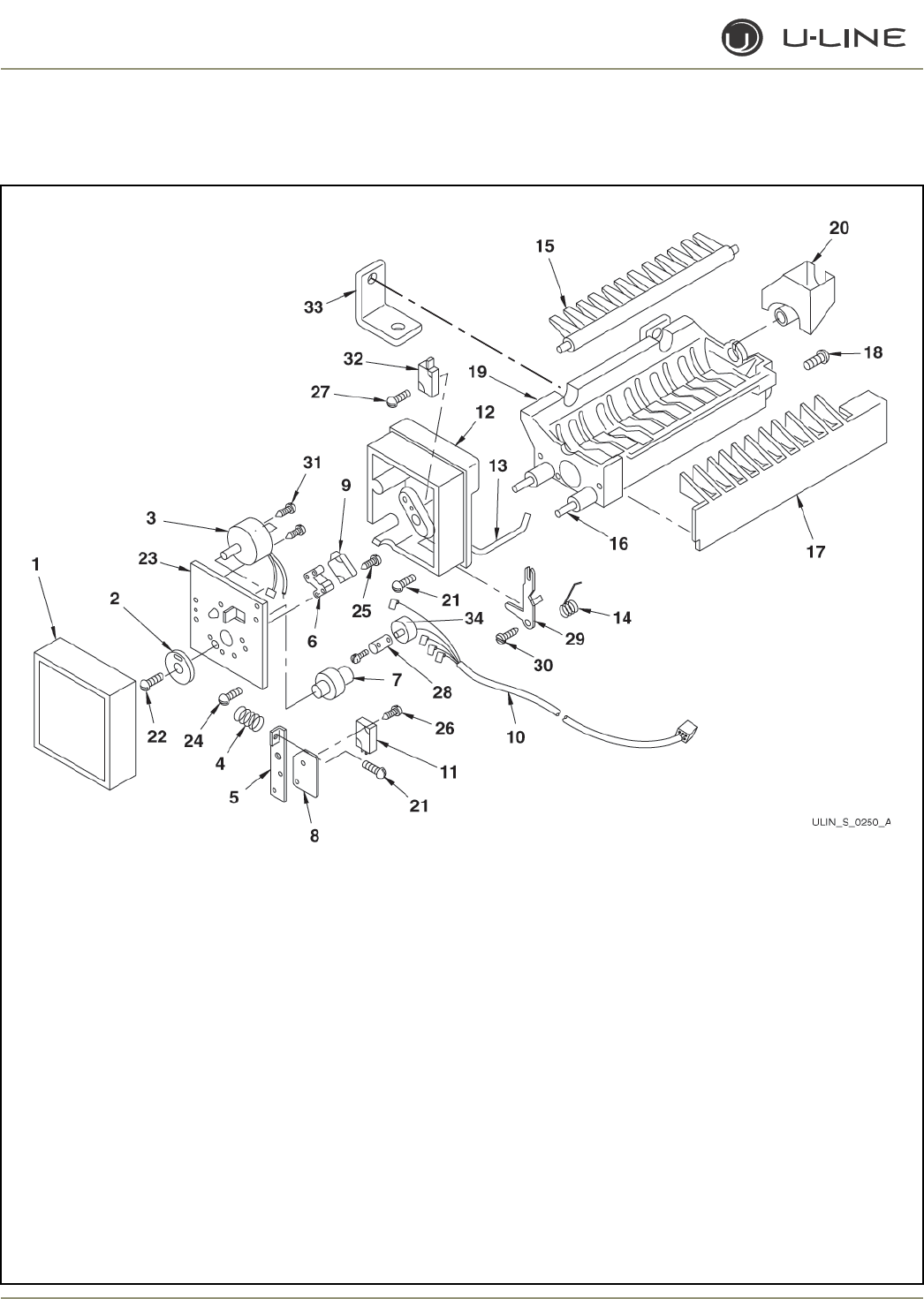
4-48
Section 4 - Parts
CO2175F (4 of 4)

4-49
Section 4 - Parts
Item Part No. Description
80-39010-00 Ice Maker Assembly
150-CO2175F Faceplate Assembly
1 627000 Cover
2 628210*† Gear
3 80-39015-00* Motor
4 627163*† Spring
5 625836*† Valve switch plate
6 31403* Switch spacer
7 627302*† Cam
8 627680* Insulator
9 2506* Hold switch
10 2918 Wire harness
11 2506* Valve switch
12 625827 Support housing
13 2886 Bin arm
14 627526 Spring, bin arm
15 627375 Ejector
16 625843-S Mold heater
17 31400 Stripper
18 489128 Screw, stripper
19 628123-S-E75 Mold and Heater Assembly
20 544304 Water cup
21 488372*† Screw, spring and housing
22 488957*† Screw, gear
23 11641*† Faceplate
24 41375 Screw, plate
25 488361* Screw, long sw
26 488362* Screw, short sw
27 488360 Screw, bin sw
28 625829 Clamp
29 625830 Arm lever
30 627199 Screw, arm lever
31 488622* Screw, motor
32 2506* Bin switch
33 42166 Support bracket
34 2917 Limit Switch
Not 68092 Thermistor
Shown
* included with 150-CO2175 faceplate assembly
† included with 80-39015-00 motor
CO2175F (4 of 4)
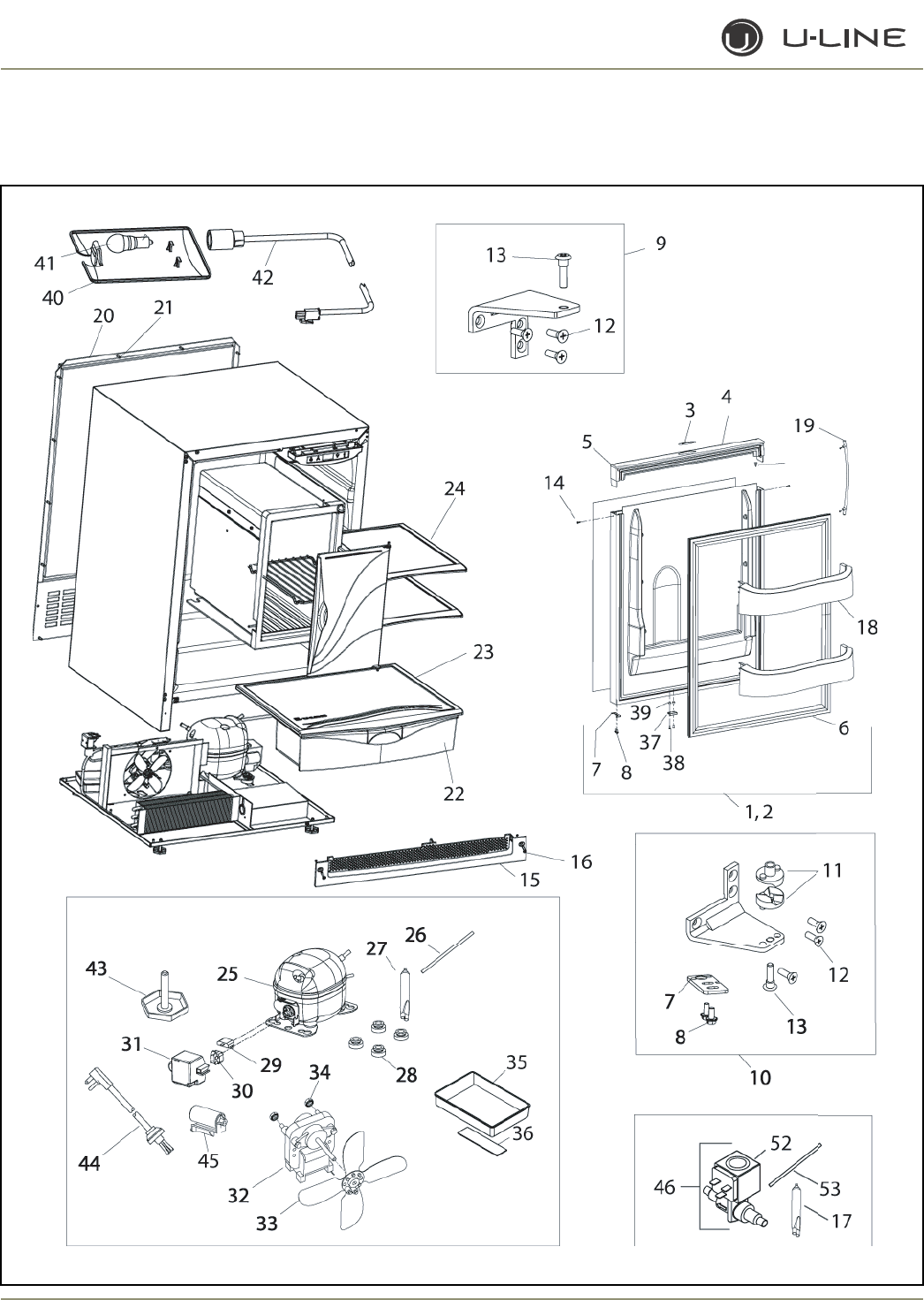
4-50
Section 4 - Parts
2175RF (1 of 3)

4-51
Section 4 - Parts
Item Part No. Part No. Part No. Description
Black White Stainless Steel
1 80-17060-01 80-17060-02 80-17075-01 Door Assembly, RH
2 80-17060-01 80-17060-02 80-17075-02 Door Assembly, LH
3 23025 23025 23025 Nameplate
4 26070-01-S 26070-02-S N/A Handle Assembly
5 42173-BLK 42173-NAT N/A Hole plug (included with handle assembly)
6 12094-01 12094-03 12094-02 Gasket, door
7 11901-1-BLK-S 11901-1-BLK-S 11994-BLK Pivot plate
8 42161-ZP 42161-ZP 42161-ZP Screw, pivot plate
9 11898-S-BLK 11898-S-KIT 11995-S-SS Hinge Assembly, top
10 11899-S-BLK 11899-S-KIT 11996-S-SS Hinge Assembly, bottom
11 31673-S 31673-S 31673-S Door Closer Assembly
12 42101-BLK 42101-ZP 42101-SS Screw, hinge (included with hinge assembly)
13 42096 42096 42096 Pivot post (included with hinge assembly)
14 41604 41725 N/A Screw, handle (included with handle assembly)
15 80-29010-01 80-29010-02 80-29010-03 Grille
16 20033-BLK 20033-ZP 20033-ZP Screw (included with grille)
17 2692 2692 2692 Dryer (included with 73002-FFS)
18 31686 31686 31686 Door Shelf
19 N/A N/A 14160-01 Towel Bar Handle Assembly
20 11969 11969 11969 Back panel
21 41342 41342 41342 Screw, back panel
22 31685 31685 31685 Crisper drawer
23 31689 31689 31689 Crisper shelf
24 31696 31696 31696 Glass shelf
25 5408-FFS 5408-FFS 5408-FFS Compressor
26 2800 2800 2800 Process tube
27 2692 2692 2692 Dryer
28 31021 31021 31021 Grommet
29 71020 71020 71020 Overload
30 71021 71021 71021 Relay
2175RF (1 of 3)
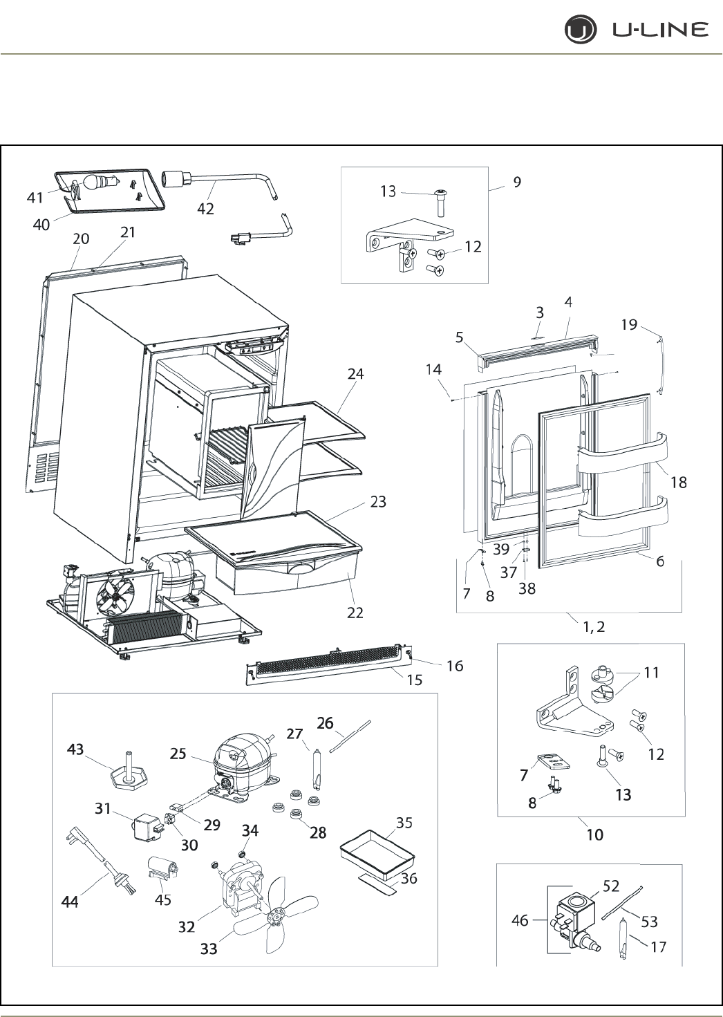
4-52
Section 4 - Parts
2175RF (2 of 3)

4-53
Section 4 - Parts
Item Part No. Part No. Part No. Description
Black White Stainless Steel
31 5408-CAP 5408-CAP 5408-CAP Cover
32 5263-S 5263-S 5263-S Fan motor, condenser
33 5188 5188 5188 Fan blade, condenser
34 41787 41787 41787 Nut (included with 5263-S)
35 31550-1-S 31550-1-S 31550-1-S Drain Pan Assembly
36 31664 31664 31664 Tape
37 66016 66016 66016 Magnet
38 20050 20050 20050 Screw, magnet
39 66019 66019 66019 Spacer, nylon
40 11859 11859 11859 Lens, light housing
41 31317 31317 31317 Light bulb, 10W, 120V
42 2891-01 2891-01 2891-01 Light Socket Assembly
43 41319 41319 41319 Foot, leveler, 1/4-20
44 2946 2946 2946 Power cord
45 71022 71022 71022 Capacitor
46 73002-FFS 73002-FFS 73002-FFS Hot Gas Valve Assembly, Danfoss
52 73002-2 73002-2 73002-2 Solenoid only (included with 73002-FFS)
53 2800 2800 2800 Process tube (included with 73002-FFS)
Not N/A N/A 14159-01 Commerical handle (SS accessory only)
Shown
2175RF (2 of 3)
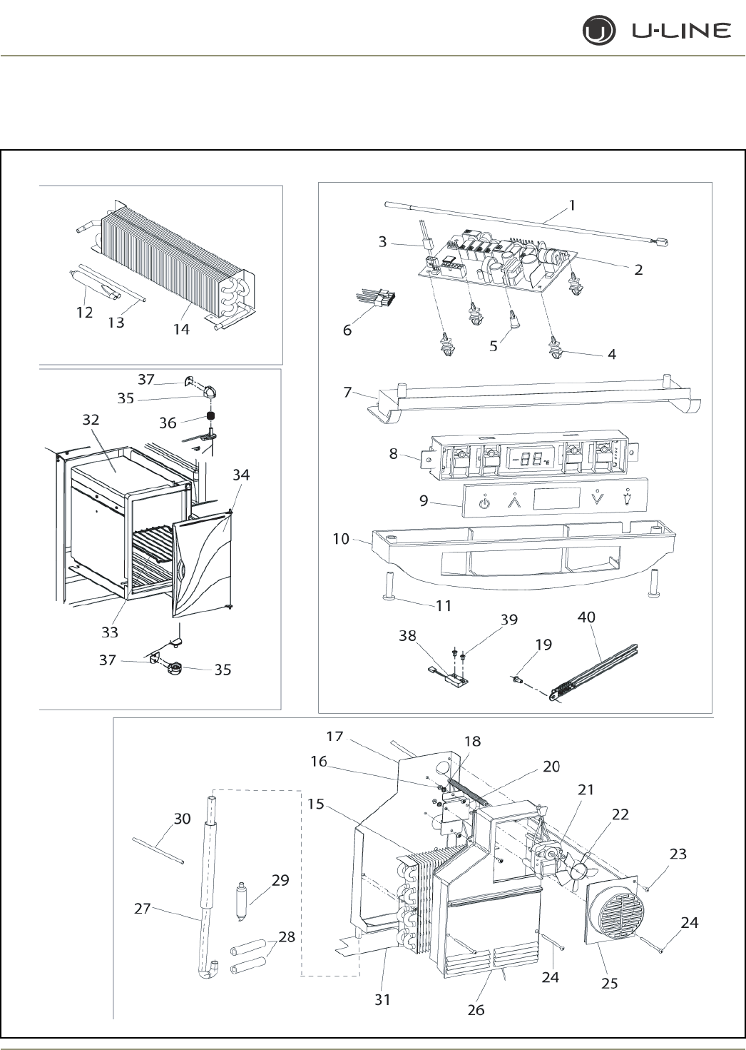
4-54
Section 4 - Parts
2175RF (3 of 3)

4-55
Section 4 - Parts
Item Part No. Part No. Part No. Description
Black White Stainless Steel
1 68092 68092 68092 Thermistor, quick connect white
2 68072-S 68072-S 68072-S Circuit Board Assembly
3 68080 68080 68080 Switch jumper (included with 68072-S)
4 41992 41992 41992 Support, circuit board (included with 68072-S)
5 41993 41993 41993 Support, circuit board (included with 68072-S)
6 2950-02 2950-02 2950-02 Wire connector, 12-pin
7 26086 26086 26086 Liner, baseplate
8 68074 68074 68074 Display Assembly, Echelon
9 68059-01 68059-01 68059-01 Display glass, Echelon control
10 26089 26089 26089 Housing, display
11 42162 42162 42162 Screw, 8-18 x .75, plastite
12 2692 2692 2692 Dryer (included with 2303-FFS)
13 2800 2800 2800 Process tube (included with 2303-FFS)
14 2303-FFS 2303-FFS 2303-FFS Condenser Assembly
15 2334-FFS 2334-FFS 2334-FFS Evaporator Assembly (includes heat exchanger)
16 41158 41158 41158 Nut
17 2349 2349 2349 Drain Pan Assembly
18 41566 41566 41566 Washer
19 31434-1 31434-1 31434-1 Rivet
20 11855 11855 11855 Bracket, fan motor
21 5434 5434 5434 Fan motor, evaporator
22 31656 31656 31656 Fan blade, evaporator
23 42129 42129 42129 Screw
24 42099 42099 42099 Screw
25 11952 11952 11952 Fan cover, evaporator
26 11955 11955 11955 Cover, evaporator
27 31731 31731 31731 Drain tube
28 31410 31410 31410 Armaflex (included with #15)
29 2692 2692 2692 Dryer (included with #15)
30 2800 2800 2800 Process tube (included with #15)
31 66005 66005 66005 Heater, drain pan
32 80-35001-S 80-35001-S 80-35001-S Freezer Housing Assembly
33 2348 2348 2348 Freezer shelf
34 26069-S 26069-S 26069-S Freezer Door Assembly
(includes 35, 36 & 37)
35 12013-S 12013-S 12013-S Freezer Door Hinge Assembly (top & bottom)
36 42135 42135 42135 Spring, freezer door hinge
37 42157 42157 42157 Tape
38 66010 66010 66010 Reed Switch
39 20026 20026 20026 Screw
40 26091 26091 26091 Cover, thermistor
Not 31154 31154 31154 Armaflex (included with #15)
Shown
Not 35014 35014 35014 Tape, drain pan heater
Shown
2175RF (3 of 3)
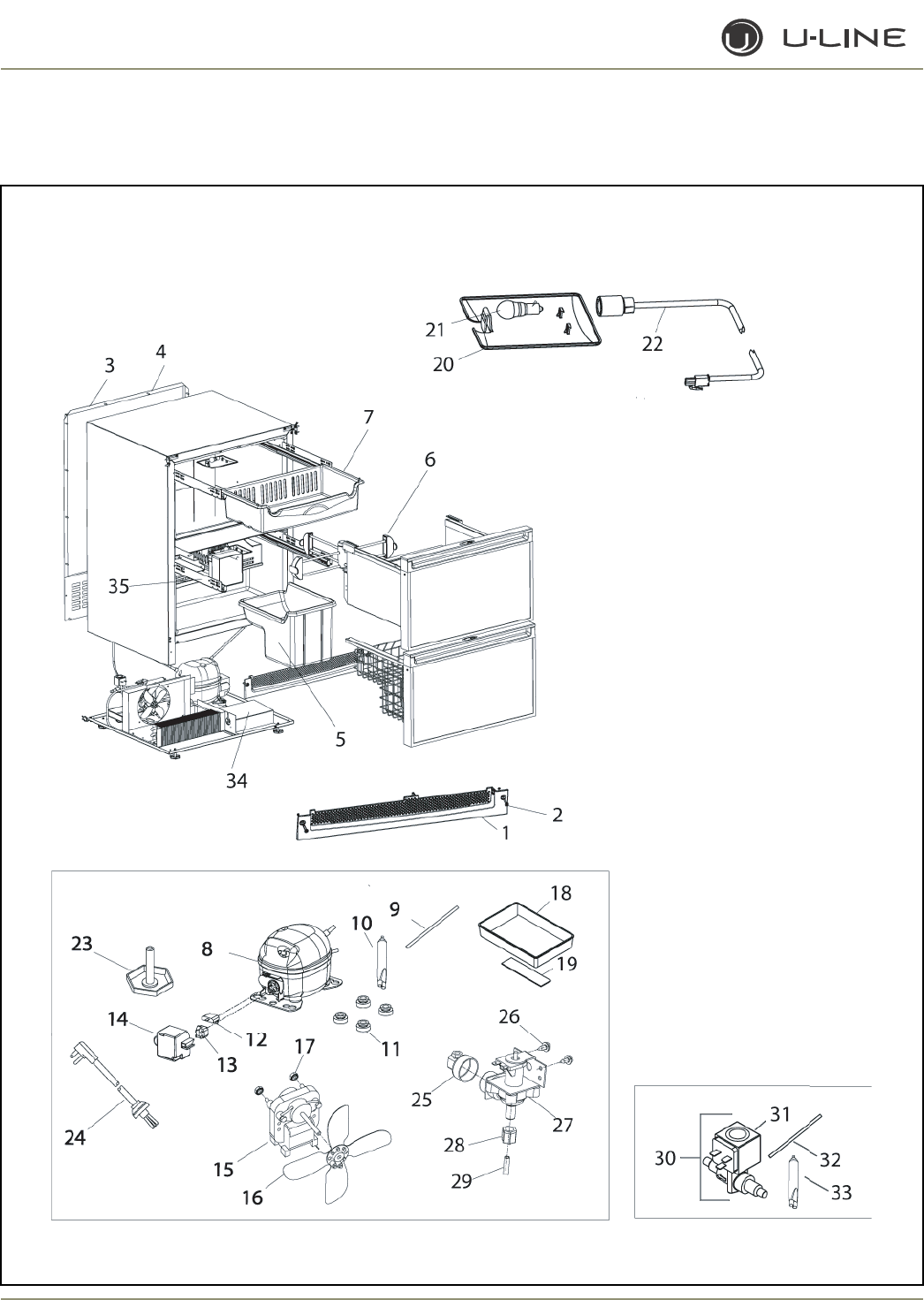
4-56
Section 4 - Parts
CO2175DWR/CO2275DWR (1 of 4)

4-57
Section 4 - Parts
Item Part No. Part No. Description
Black Stainless Steel
1 80-29010-01 80-29010-03 Grille
2 20033-BLK 20033-ZP Screw (included with grille)
3 11969 11969 Back panel
4 41342 41342 Screw, back panel
5 26014 26014 Ice bucket
6 80-48001-00 80-48001-00 Drawer Organizer Assembly
7 26000 26000 Top crisper
8 70081-FFS 70081-FFS Compressor
9 2800 2800 Process tube
10 72018 72018 Dryer
11 31021 31021 Grommet
12 71027 71027 Overload
13 71028 71028 Relay
14 70081-CAP 70081-CAP Cover
15 5263-S 5263-S Fan motor, condenser
16 5188 5188 Fan blade, condenser
17 41787 41787 Nut (included with 5263-S)
18 31550-1-S 31550-1-S Drain Pan Assembly
19 31664 31664 Tape
20 11859 11859 Lens, light housing
21 31317 31317 Light bulb, 10W, 120V
22 2891-01 2891-01 Light Socket Assembly
23 41319 41319 Foot, leveler
24 2946 2946 Power cord
25 41826 41826 Fitting, brass, 90°
26 41893-ZP 41893-ZP Screw
27 2552A 2552A Water valve
28 41254 41254 Plastic Nut & Sleeve Assembly
29 404-CO207DWR 404-CO207DWR Water Line Assembly
30 73002-FFS 73002-FFS Hot Gas Valve Assembly, Danfoss
31 73002-2 73002-2 Solenoid only (included with 73002-FFS)
32 2800 2800 Process tube (included with 73002-FFS)
33 72018 72018 Dryer (included with 73002-FFS)
34 14147-01 14147-01 Splash guard
35 80-47002-00 80-47002-00 Slide Assembly (set of 2)
CO2175DWR/CO2275DWR (1 of 4)
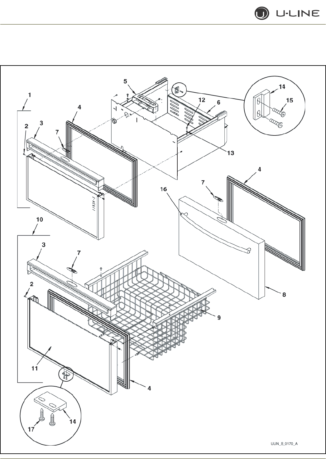
4-58
Section 4 - Parts
CO2175DWR/CO2275DWR (2 of 4)

4-59
Section 4 - Parts
Item Part No. Part No. Description
Black Stainless Steel
1 2175DWR-TOP-BLK N/A Drawer Front Assembly, top
2 41604 N/A Screw, handle
3 26070-05-S N/A Overlay handle
4 12094-07 12094-08 Gasket, drawer
5 26094 26094 Display housing
6 14138-02 14138-02 Drawer, no front, top
7 23025 23025 Nameplate
8 N/A 11939-05-S Stainless steel wrap only (includes handle)
9 18025 18025 Freezer basket, no front, bottom
10 2175DWR-BTM-BLK N/A Drawer Front Assembly, bottom
11 11933-18-BLK N/A Front panel only
12 41156 41156 Screw
13 41965 41965 Spacer, nylon
14 66016 66016 Magnet
15 41259 41259 Rivet, magnet
16 N/A 14160-05 Towel Bar Handle Assembly
17 20026 20026 Screw, magnet
Not 26070-01-S N/A Full handle
Shown
Not N/A 14159-05 Commercial handle (accessory only)
Shown
CO2175DWR/CO2275DWR (2 of 4)
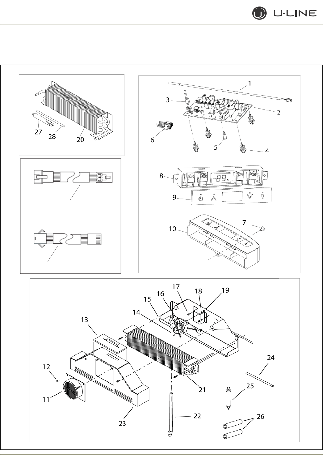
4-60
Section 4 - Parts
29
30
CO2175DWR/CO2275DWR (3 of 4)

4-61
Section 4 - Parts
Item Part No. Part No. Description
Black Stainless Steel
1 68092 68092 Thermistor, quick connect white
2 68072-S 68072-S Circuit Board Assembly
3 68080 68080 Switch jumper (included with 68072-S)
4 41992 41992 Support, circuit board (included with 68072-S)
5 41993 41993 Support, circuit board (included with 68072-S)
6 2950-03 2950-03 Wire connector, 12-pin
7 20004 20004 Screw, 8-18 x .75, plastite
8 68074 68074 Display Assembly, Echelon
9 68059-01 68059-01 Display glass, Echelon control
10 26094 26094 Housing, display
11 11952 11952 Fan cover, evaporator
12 4816 4816 Screw, fan cover, evaporator
13 35005 35005 Chimney panel insulator
14 31656 31656 Fan blade, evaporator
15 14038 14038 Drain pan
16 5434 5434 Fan motor, evaporator
17 41444 41444 Screw, fan motor
18 41566 41566 Washer
19 41158 41158 Nut
20 2303-FFS 2303-FFS Condenser Assembly
21 74002-S 74002-S Evaporator Assembly (includes heat exchanger)
22 31726 31726 Drain tube
23 11952 11952 Cover, evaporator
24 2800 2800 Process tube (included with 74002-S)
25 72018 72018 Dryer (included with 74002-S)
26 31154 31154 Armaflex (included with 74002-S)
27 72018 72018 Dryer (included with 2303-FFS
28 2800 2800 Process tube (included with 2303-FFS)
29 2953 2953 Wire from display
30 2952 2952 Wire from main board
CO2175DWR/CO2275DWR (3 of 4)
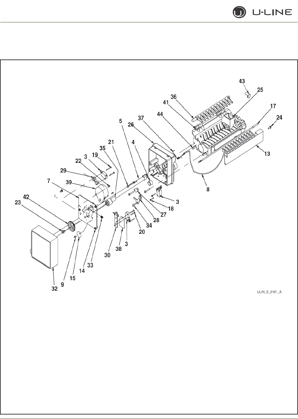
4-62
Section 4 - Parts
CO2275DWR (4 of 4)

4-63
Section 4 - Parts
Item Part No. Description
80-39011-00 Ice Maker Assembly
150-DWRCO Faceplate Assembly
1 2506* Hold switch
2 2506* Bin switch
3 2506* Valve switch
4 2917 Limit switch
5 2918 Wire harness
7 11641*† Face plate
8 18031 Bin arm
9 20044 Screw
13 31400 Stripper
14 41375 Screw, plate
15 41434 Warning label
17 68092 Thermistor
18 488360 Screw, bin, sw
19 488361* Screw, long, sw
20 488362* Screw, short, sw
21 488372*† Screw, spring and housing
22 488622* Screw, motor
23 488957*† Screw, gear
24 489128 Screw, stripper
25 544304 Water cup
26 625827 Support housing
27 625829 Clamp
28 625830 Arm lever
29 31403* Spacer, switch
30 625836*† Valve switch plate
32 627000-BLK Cover, black
33 627163*† Spring
34 627199 Screw, arm lever
35 627302† Cam
36 627375 Ejector
37 627526 Spring, bin arm
38 627680* Insulator
39 80-39015-00* Motor
41 628123-S-E75 Mold and Heater Assembly
42 628210*† Gear
43 652604 Waterline clip
44 625843-S Mold heater
* included with 150-DWRCO
† included with 80-39015-00 motor
CO2275DWR (4 of 4)
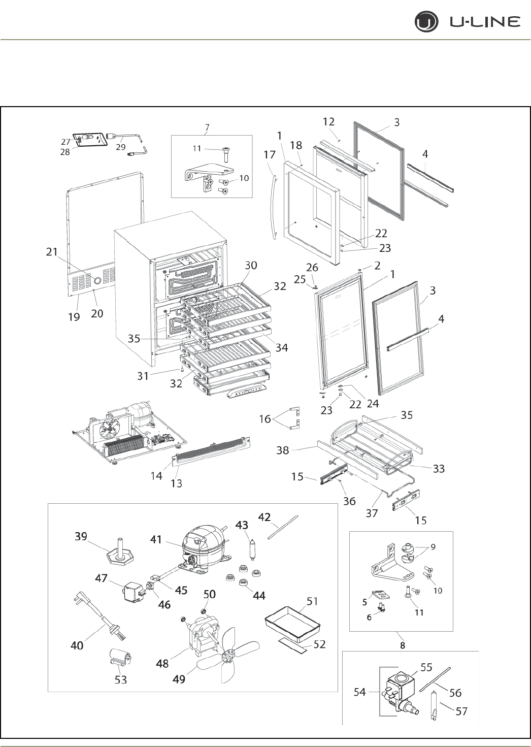
4-64
Section 4 - Parts
2275ZWC/2275ZWCOL (1 of 3)

4-65
Section 4 - Parts
Item Part No. Part No. Description
Overlay Stainless Steel
1 80-17104-01 80-17100-13 Door, LH
80-17104-01 80-17100-03 Door, RH
2 42173-BLK N/A Hole plug (included with handle assembly)
3 12094-01 12094-01 Gasket, door
4 12095-10 12095-10 Gasket, door, center
5 11994-BLK-S 11994-BLK-S Pivot plate
6 42161-ZP 42161-SS Screw, pivot plate
7 11995-S-BLK 11995-S-SS Hinge Assembly, top
8 11996-S-BLK 11996-S-SS Hinge Assembly, bottom
9 31673-S 31673-S Door Closer Assembly
10 42101-BLK 42101-SS Screw, hinge (included with hinge assembly)
11 42096 42096 Pivot post (included with hinge assembly)
12 N/A 42174 Screw, handle
13 80-29010-01 80-29010-03 Grille
14 20033-BLK 20033-ZP Screw (included with grille)
15 23031-03 23031-03 Caddy Slide Assembly (set of 2)
16 16002 16002 Hinge Backing Plate Assembly
17 N/A 14160-01 Towel Bar Handle Assembly
18 N/A 42003 Screw (included with towel bar handle)
19 11969 11969 Back panel
20 41342 41342 Screw, back panel
21 42125 42125 Hole cover, perforated
22 66016 66016 Magnet
23 20050 20050 Screw, magnet
24 66019 66019 Magnet Spacer
25 14203 N/A Pivot plate, top
26 20023 N/A Screw, pivot plate, top
27 11859 11859 Lens, light housing
28 31317 31317 Light bulb, 10W, 120V
29 2891-01 2891-01 Light Socket Assembly
30 18066-Vinyl 18066-Vinyl Wine Rack
31 4816 4816 Screw, #18-18 x 1/2 (included with 23027-03)
32 23027-03 23027-03 Slide Assembly (set of 2)
33 18059 18059 Wine Caddy Assembly
34 39004-01 39004-01 Wood, front
35 42106 42106 Screw, wood, #6-32 x .38
36 4816 4816 Screw, #8-18 x 1/2 (included with 23031-03)
37 18058 18058 Wine Caddy
38 39011 39011 Wood, front (included with 18059)
Not N/A 14159-01 Commercial handle (SS accessory only)
Shown
2275ZWC/2275ZWCOL (1 of 3)
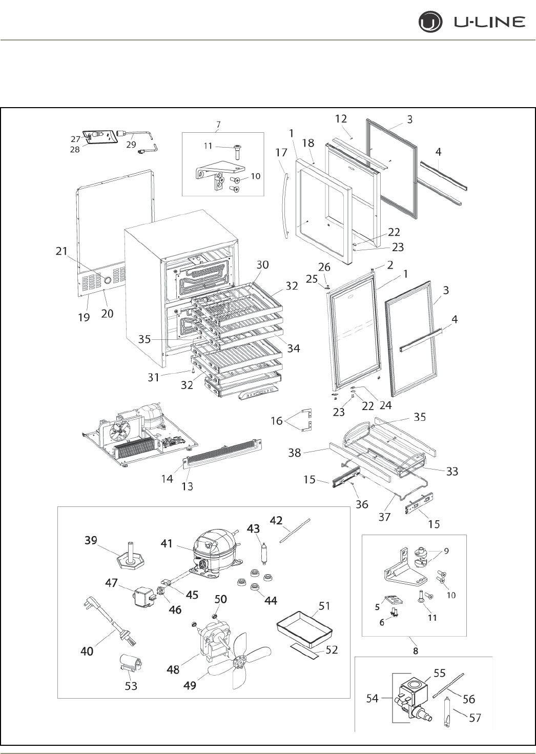
4-66
Section 4 - Parts
2275ZWC/2275ZWCOL (2 of 3)

4-67
Section 4 - Parts
Item Part No. Part No. Description
Overlay Stainless Steel
39 41319 41319 Foot, leveler, 1/4-20
40 2948 2948 Power cord
41 70077-S 70077-S Compressor
42 2800 2800 Process tube (included with compressor)
43 2694 2694 Dryer (included with compressor)
44 31021 31021 Grommet (included with compressor)
45 71009 71009 Overload (included with compressor)
46 71010 71010 Relay (included with compressor)
47 70077-CAP 70077-CAP Cover (included with compressor)
48 5263-S 5263-S Fan motor, condenser
49 5188 5188 Fan blade, condenser
50 41787 41787 Nut (included with 5263-S)
51 31550-1-S 31550-1-S Drain Pan Assembly
52 31664 31664 Tape (included with #51)
53 71013 71013 Capacitor
54 73002-S 73002-S Hot Gas Valve Assembly, Danfoss
55 73002-2 73002-2 Solenoid only (included with 73002-S)
56 2800 2800 Process tube (included with 73002-S)
57 2694 2694 Dryer (included with 73002-S)
2275ZWC/2275ZWCOL (2 of 3)
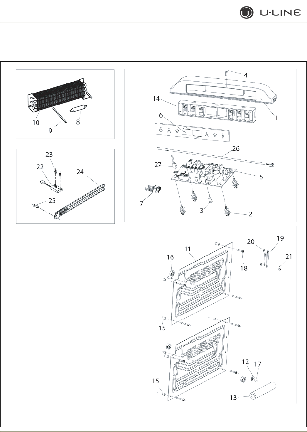
4-68
Section 4 - Parts
2275ZWC/2275ZWCOL (3 of 3)

4-69
Section 4 - Parts
Item Part No. Part No. Description
Overlay Stainless Steel
1 26100 26100 Display housing
2 41992 41992 Support, circuit board (included with 68084-S)
3 41993 41993 Support, circuit board (included with 68084-S)
4 42106 42106 Screw, #6-32 x .38
5 68084-S 68084-S Main Circuit Board Assembly
6 68091-01 68091-01 Glass, display
7 2950-04 2950-04 Pin connector
8 2694 2694 Dryer (included with 2303-S)
9 2800 2800 Process tube (included with 2303-S)
10 2303-S 2303-S Condenser Asssembly
11 2649-02-S 2649-02-S Evaporator Assembly
12 21009 21009 Clamp, cable
13 31154 31154 Insulation
14 68090 68090 Display
15 21024 21024 Spacer
16 31386 31386 Bushing, black
17 31434-2 31434-2 Rivet, black
18 41855-02 41855-02 Screw, #8-8 x 1.25, SS
19 11835 11835 Clamp, control bulb
20 41158 41158 Nut
21 41156-02 41156-02 Screw
22 66010 66010 Reed switch
23 20026 20026 Screw, reed switch
24 26091-02 26091-02 Cover, thermistor
25 21012-BLK 21012-BLK Rivet
26 68092 68092 Thermistor
27 68080 68080 Jumper (included with 68084-S)
2275ZWC/2275ZWCOL (3 of 3)
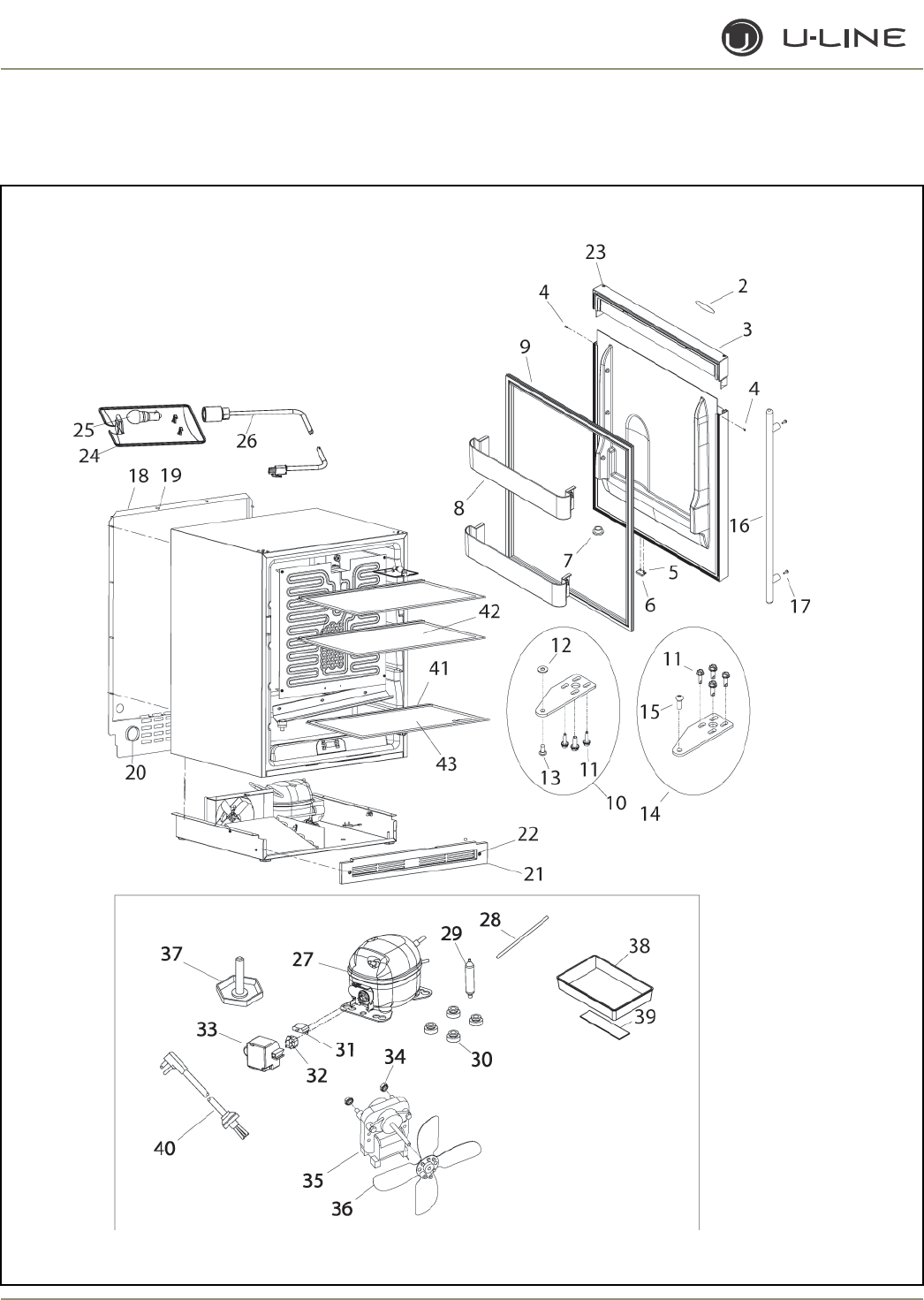
4-70
Section 4 - Parts
1175R (1 of 2)

4-71
Section 4 - Parts
Item Part No. Part No. Part No. Description
Black White Stainless Steel
1 80-17051-01 80-17051-02 80-17067-03-E Door Assembly, right-hand
N/A N/A 80-17067-13-B Door Assembly, left-hand
2 23051-01 23051-01 23051-01 Nameplate
3 26078-01 26078-02 N/A Handle Assembly
4 41604 41725 N/A Screw, handle
5 20031 20031 20031 Screw, magnet
6 66016 66016 66016 Magnet
7 31309-BLK 31309-WHT N/A Bushing, door
8 26031 26031 26031 Door shelf
9 31493-4-BLK 31493-4-WHT 31493-4-BLK Gasket, door
10 11849-SB-BLK 11849-SB-KIT 14136-SB Hinge Assembly, bottom
11 20042-BLK 20042-ZP 20042-BLK Screw (included with hinge assembly)
12 N/A N/A 21017 Washer (included with hinge assembly)
13 41785-SSB 41785-SSW 41785-SSB Pivot screw, bottom
(included with hinge assembly)
14 11849--ST-BLK 11849-ST-KIT 14136-ST Hinge Assembly, top
15 41747-SSB 41747-SSW 41747-SSB Pivot screw (included with hinge assembly)
16 N/A N/A 23050-01 Towel Bar Handle Assembly (SS accessory only)
18 11769 11769 11769 Back panel
19 41342 41342 41342 Screw, back panel
20 42125 42125 42125 Hole cover, solid
21 80-29094-01 80-29094-02 80-29094-01 Grille
22 20033-BLK 20033-ZP 20033-BLK Screw (included with grille)
23 31447-BLK 31447-WHT 31447-BLK Hole plug
24 11859 11859 11859 Lens, light housing
25 31317 31317 31317 Light bulb, 10W, 120V
26 2891-01 2891-01 2891-01 Light Socket Assembly
27 5400-S 5400-S 5400-S Compressor Assembly, EM130HER
28 2800 2800 2800 Process tube (included with 5400-S)
29 2694 2694 2694 Dryer (included with 5400-S)
30 31021 31021 31021 Grommet (included with 5400-S)
31 5411 5411 5411 Overload (included with 5400-S)
32 5412 5412 5412 Relay (included with 5400-S)
33 5400-CAP 5400-CAP 5400-CAP Cap (included with 5400-S)
34 41787 41787 41787 Nut (included with 5263-S)
35 5263-S 5263-S 5263-S Fan motor, condenser
36 5188 5188 5188 Fan blade, plastic
37 41319 41319 41319 Foot, leveler, 1/4-20
38 31550-1-S 31550-1-S 31550-1-S Drain pan
39 31664 31664 31664 Tape (included with 31550-1-S)
40 2938-2 2938-2 2938-2 Power cord
41 25032-1 25032-1 25032-1 Edge trim, rear
42 40010-14 40010-14 40010-14 Glass shelf
43 40010-15 40010-15 40010-15 Glass shelf
1175R (1 of 2)
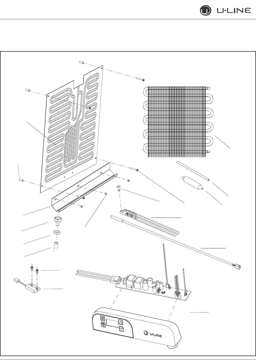
4-72
Section 4 - Parts
2
3
4
5
6
7
10
9
11
12
13
14
15
16
17
1
8
1175R (2 of 2)

4-73
Section 4 - Parts
Item Part No. Description
1 1951-S Condenser Assembly **
2 2800 Process tube
3 2694 Dryer
4 41855 Screw, evaporator
5 31434-1 Rivet, thermostat cover
6 26091 Cover, thermistor
7 68073 Thermistor, quick connect white
8 26059-02 Control Display Assembly
9 66010 Reed switch
10 20026 Screw, reed switch
11 21012-WHT Rivet, white
12 31579 Formed drain tube
13 31578 Washer, drain tube
14 11508 Drain cup
15 31391-3 Drain trough
16 31213 Spacer, evaporator
17 2333-S Evaporator Assembly **
** Includes Dryer & Process Tube
1175R (2 of 2)
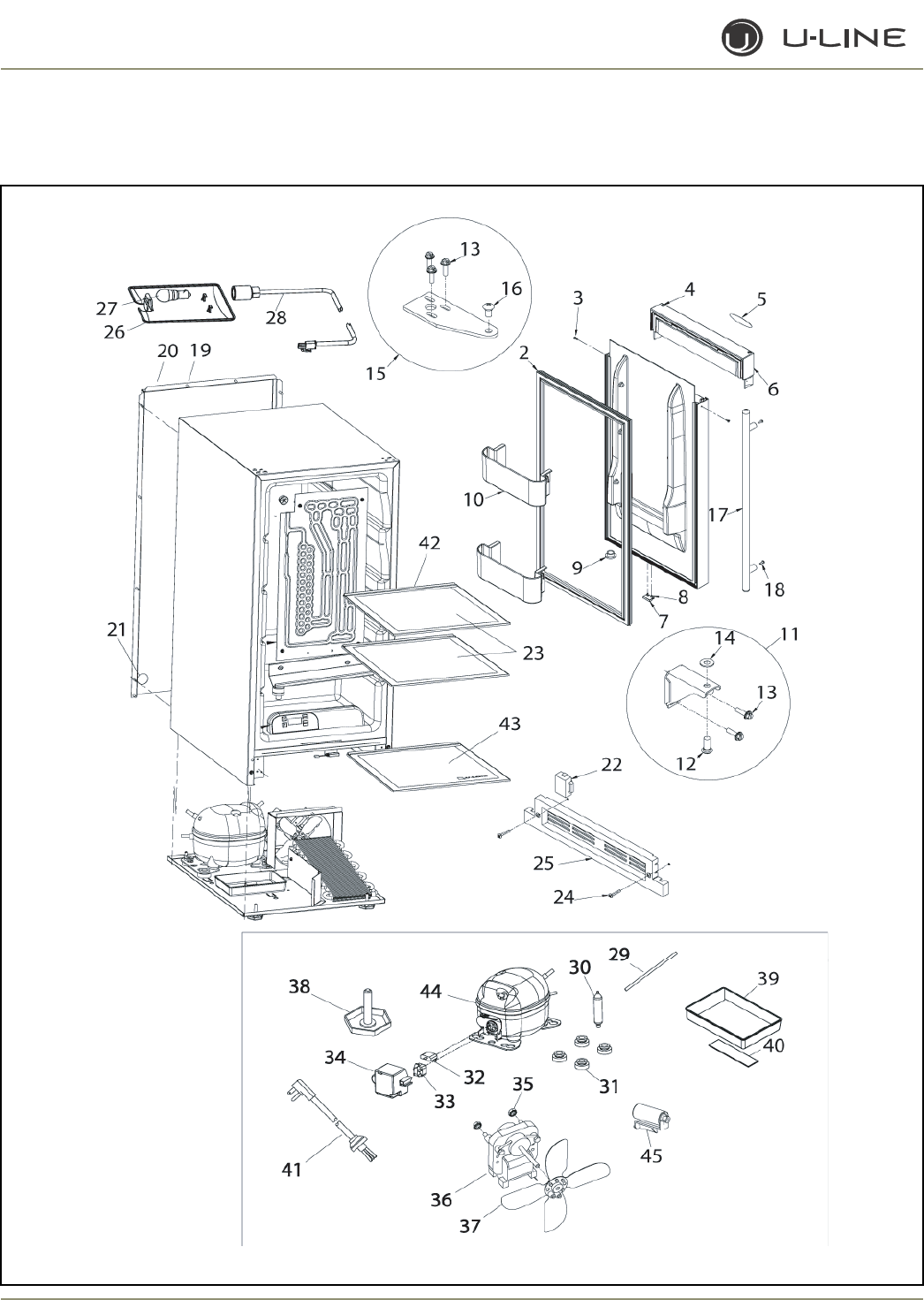
4-74
Section 4 - Parts
1115R (1 OF 2)
4-75
Section 4 - Parts
Item Part No. Part No. Description
Black Stainless Steel
1 80-17062-01 80-17066-03-C Door Assembly, RH
N/A 80-17066-13-C Door Assembly, LH
2 31493-6-BLK 31493-6-BLK Gasket, door
3 41604 N/A Screw, handle
4 31447-BLK 31447-BLK Hole plug
5 23051-01 23051-01 Nameplate
6 26077-01 N/A Handle Assembly
7 66016 66016 Magnet
8 20031 20031 Screw, magnet
9 31309-BLK N/A Bushing, door
10 26032 26032 Door shelf
11 11695-S-BLK 14127-SB Hinge Assembly, bottom
12 41785-SSB 41785-SSB Pivot screw, bottom
13 41893-BLK 41893-BLK Screw, hinge
14 N/A 21017 Washer
15 11697-STBLK 14126-ST Hinge Assembly, top
16 41747-SSB 41747-SSB Pivot screw, top
17 N/A 23050-01 Towel Bar Handle Assembly (SS accessory only)
19 41342 41342 Screw, back panel
20 41802 41802 Back panel
21 42125 42125 Hole cover, solid
22 26060-BLK 26060-BLK Hinge hole cover (included with 80-29011-01)
23 40010-17 40010-17 Glass shelf
24 20033-BLK 20033-BLK Screw (included with 80-29011-01)
25 80-29011-01 80-29011-01 Grille
26 11859 11859 Lens, light housing
27 31317 31317 Light bulb, 10W, 120V
28 2891-01 2891-01 Light Socket Assembly
29 2800 2800 Process tube (included with 70077-S)
30 2694 2694 Dryer (included with 70077-S)
31 31021 31021 Grommet (included with 70077-S)
32 71009 71009 Overload (included with 70077-S)
33 71010 71010 Relay (included with 70077-S)
34 70077-CAP 70077-CAP Cap (included with 70077-S)
35 41787 41787 Nut (included with 5263-S)
36 5263-S 5263-S Fan motor, condenser
37 5188 5188 Fan blade, plastic
38 41319 41319 Foot, leveler, 1/4-20
39 31550-1-S 31550-1-S Drain pan
40 31664 31664 Tape (included with 31550-1-S)
41 2938-2 2938-2 Power cord
42 25032-3 25032-3 Edge trim, rear
43 40010-18 40010-18 Glass shelf
44 70077-S 70077-S Compressor
45 71008 71008 Capacitor (included with 70077-S)
1115R (1 OF 2)
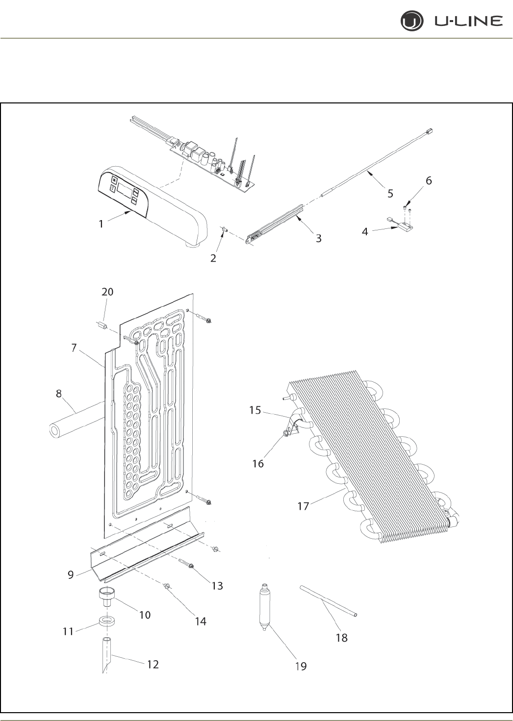
4-76
Section 4 - Parts
1115R (2 of 2)

4-77
Section 4 - Parts
Item Part No. Description
1 26059-02 Control Display Assembly
2 31434-1 Rivet, thermostat cover
3 26091 Cover, thermistor
4 66010 Reed switch
5 68073 Thermistor, quick connect white
6 41863 Rivet, reed switch
7 2878-01-S Evaporator, roll-bond
8 31154 Insulation, .38 ID x .88 OD, black
9 31391-2 Drain trough, white
10 11508 Funnel drain cup
11 31578 Washer, drain tube, white
12 31594 Drain tube
13 41855 Screw, 8-18 x 1.25, SS
14 21012-WHT Rivet, white
15 41318 Mounting clamp
16 41342 Mounting screw
17 2223-S Condenser Assembly
18 2800 Process tube (included with 2223-S)
19 2694 Dryer, R-134A (included with 2223-S)
20 31213 Spacer
1115R (2 of 2)
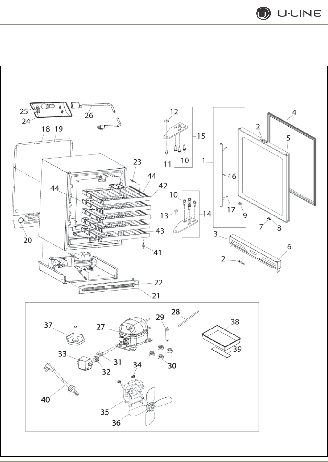
4-78
Section 4 - Parts
1175WC (1 of 2)

4-79
Section 4 - Parts
Item Part No. Part No. Description
Black Stainless Steel
1 80-17070-01 80-17069-03-G Door Assembly, SS door is field reversable
2 23051-01 23051-01 Nameplate
3 26078-01 N/A Handle Assembly
4 31493-4-BLK 31493-4-BLK Gasket, door
5 31447-BLK 31447-BLK Hole plug
6 41604 N/A Screw, handle
7 20031 20031 Screw, magnet
8 66016 66016 Magnet
9 31309-BLK N/A Bushing, door
10 20042-BLK 20042-BLK Screw, hinge (included with hinge assembly)
11 41747-SSB 41747-SSB Pivot screw, bottom (included with hinge assembly)
12 N/A 21017 Washer (included with hinge assembly)
13 41785-SSB 41785-SSB Pivot screw, top (included with hinge assembly)
14 11849-ST-BLK 14136-ST Hinge Assembly, top
15 11849-SB-BLK 14136-SB Hinge Assembly, bottom
16 N/A 23050-01 Towel Bar Handle Assembly (SS accessory only)
18 11769 11769 Back panel
19 41342 41342 Screw, back panel
20 42125 42125 Hole cover, solid
21 80-29094-01 80-29094-01 Grille
22 20033-BLK 20033-BLK Screw (included with grille)
23 42106 42106 Screw, wood
24 11859 11859 Lens, light housing
25 31317 31317 Light bulb, 10W, 120V
26 2891-01 2891-01 Light Socket Assembly
27 5400-S 5400-S Compressor Assembly, EM130HER
28 2800 2800 Process tube (included with 5400-S)
29 2694 2694 Dryer (included with 5400-S)
30 31021 31021 Grommet (included with 5400-S)
31 5411 5411 Overload (included with 5400-S)
32 5412 5412 Relay (included with 5400-S)
33 5400-CAP 5400-CAP Cap (included with 5400-S)
34 41787 41787 Nut (included with 5263-S)
35 5263-S 5263-S Fan motor, condenser
36 5188 5188 Fan blade, plastic
37 41319 41319 Foot, leveler, 1/4-20
38 31550-1-S 31550-1-S Drain pan
39 31664 31664 Tape (included with 31550-1-S)
40 2938-2 2938-2 Power cord
41 4816 4816 Screw
42 11988-03 11988-03 Wood front
43 18066-01 18066-01 Wine rack
44 23026-03-S 23026-03-S Slide Assembly (set of 2)
Not
Shown 26147 26147 Door Spacer, for Field Reversable Doors
1175WC (1 of 2)
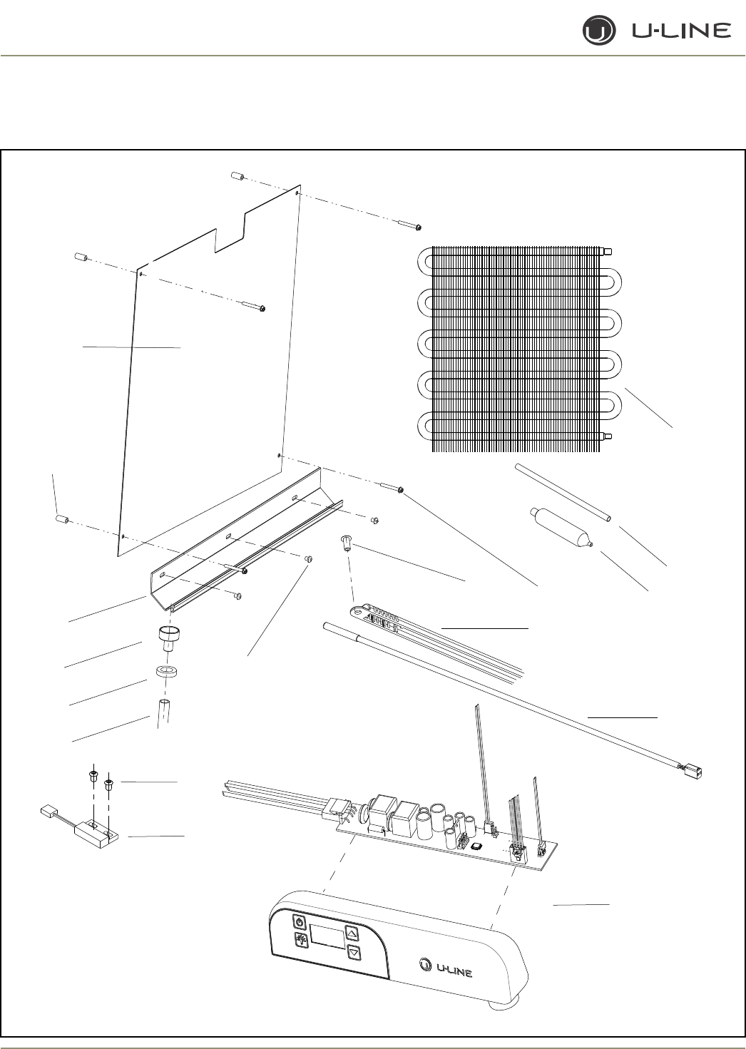
4-80
Section 4 - Parts
2
3
4
5
6
7
10
9
11
12
13
14
15
16
17
1
8
1175WC (2 of 2)

4-81
Section 4 - Parts
Item Part No. Description
1 1951-S Condenser Assembly **
2 2800 Process tube
3 2694 Dryer
4 41855 Screw, evaporator SS
41855-02 Screw, evaporator Black
5 31434-1 Rivet, thermostat cover White
31434-2 Rivet, thermostat cover Black
6 26091 Cover, thermistor White
26091-03 Cover, thermistor Black
7 68073 Thermistor, quick connect white
8 26058 Control Display Assembly White
26059-03 Control Display Assembly Black
9 66010 Reed switch
10 20026 Screw, reed switch
11 21012-WHT Rivet, White
21012-BLK Rivet, Black
12 31579 Drain tube
13 31578 Washer, drain tube White
31578-02 Washer, drain tube Black
14 11508 Drain cup White
11508-02 Drain cup Black
15 31391-3 Drain trough, White
31391-7 Drain trough, Black
16 31213 Spacer, evaporator
17 2186-S Evaporator Assembly White **
2186-02-S Evaporator Assembly Black **
** Includes dryer & Process Tube
1175WC (2 of 2)
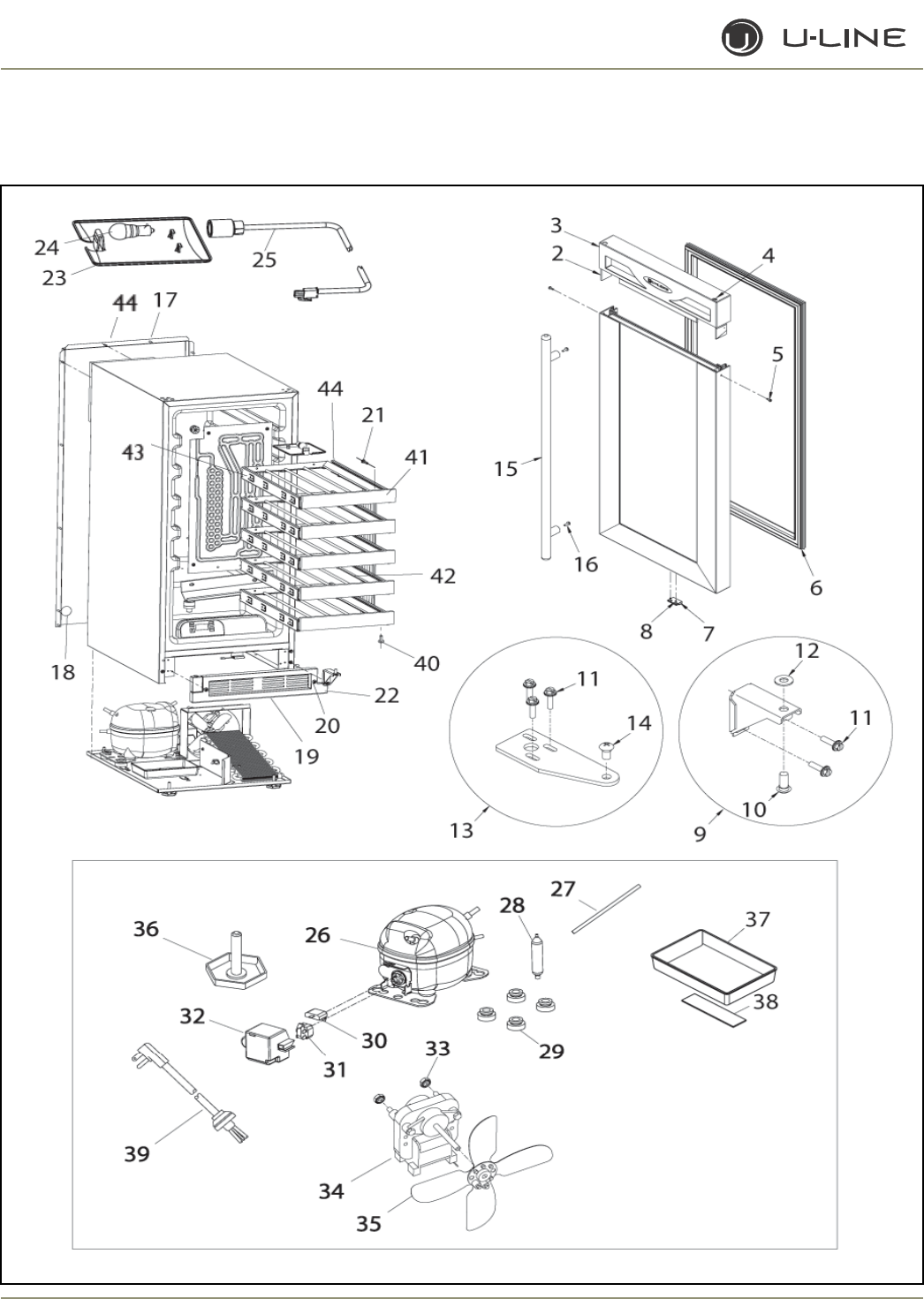
4-82
Section 4 - Parts
1115WC (1 of 2)

4-83
Section 4 - Parts
Item Part No. Part No. Description
Black Stainless Steel
1 80-17063-01-D 80-17068-03-G Door Assembly, SS Door is Field Reversable
2 23051-01 23051-01 Nameplate
3 26077-01 N/A Handle Assembly
4 31447-BLK 31447-BLK Hole plug
5 41604 N/A Screw, handle
6 31493-6-BLK 31493-6-BLK Gasket, door
7 66016 66016 Magnet
8 20031 20031 Screw, magnet
9 11695-S-BLK 14127-SB Hinge Assembly, bottom
10 41785-SSB 41785-SSB Pivot screw, bottom (included with hinge assembly)
11 41893-BLK 41893-BLK Screw, hinge (included with hinge assembly)
12 N/A 21017 Washer (included with hinge assembly)
13 11697-STB 14126-ST Hinge Assembly, top
14 41747-SSB 41747-SSB Pivot screw, top
15 N/A 23050-01 Towel Bar Handle Assembly (SS accessory only)
17 41342 41342 Screw, back panel
18 42125 42125 Hole cover, solid
19 80-29011-01 80-29011-01 Grille
20 20033-BLK 20033-BLK Screw (included with grille)
21 42106 42106 Screw, wood
22 26060-BLK 26060-BLK Hinge hole cover
23 11859 11859 Lens, light housing
24 31317 31317 Light bulb, 10W, 120V
25 2891-01 2891-01 Light Socket Assembly
26 5400-S 5400-S Compressor Assembly, EM130HER
27 2800 2800 Process tube (included with 5400-S)
28 2694 2694 Dryer (included with 5400-S)
29 31021 31021 Grommet (included with 5400-S)
30 5411 5411 Overload (included with 5400-S)
31 5412 5412 Relay (included with 5400-S)
32 5400-CAP 5400-CAP Cap (included with 5400-S)
33 41787 41787 Nut (included with 5263-S)
34 5263-S 5263-S Fan motor, condenser
35 5188 5188 Fan blade, plastic
36 41319 41319 Foot, leveler, 1/4-20
37 31550-1-S 31550-1-S Drain pan
38 31664 31664 Tape (included with 31550-1-S)
39 2938-2 2938-2 Power cord
40 4816 4816 Screw
41 11988-04 11988-04 Wood front
42 18067 18067 Wine rack metal
18067-01 18067-01 Wine rack black
43 23026-03-S 23026-03-S Slide Assembly (set of 2)
44 41802 41802 Back Panel
1115WC (1 of 2)
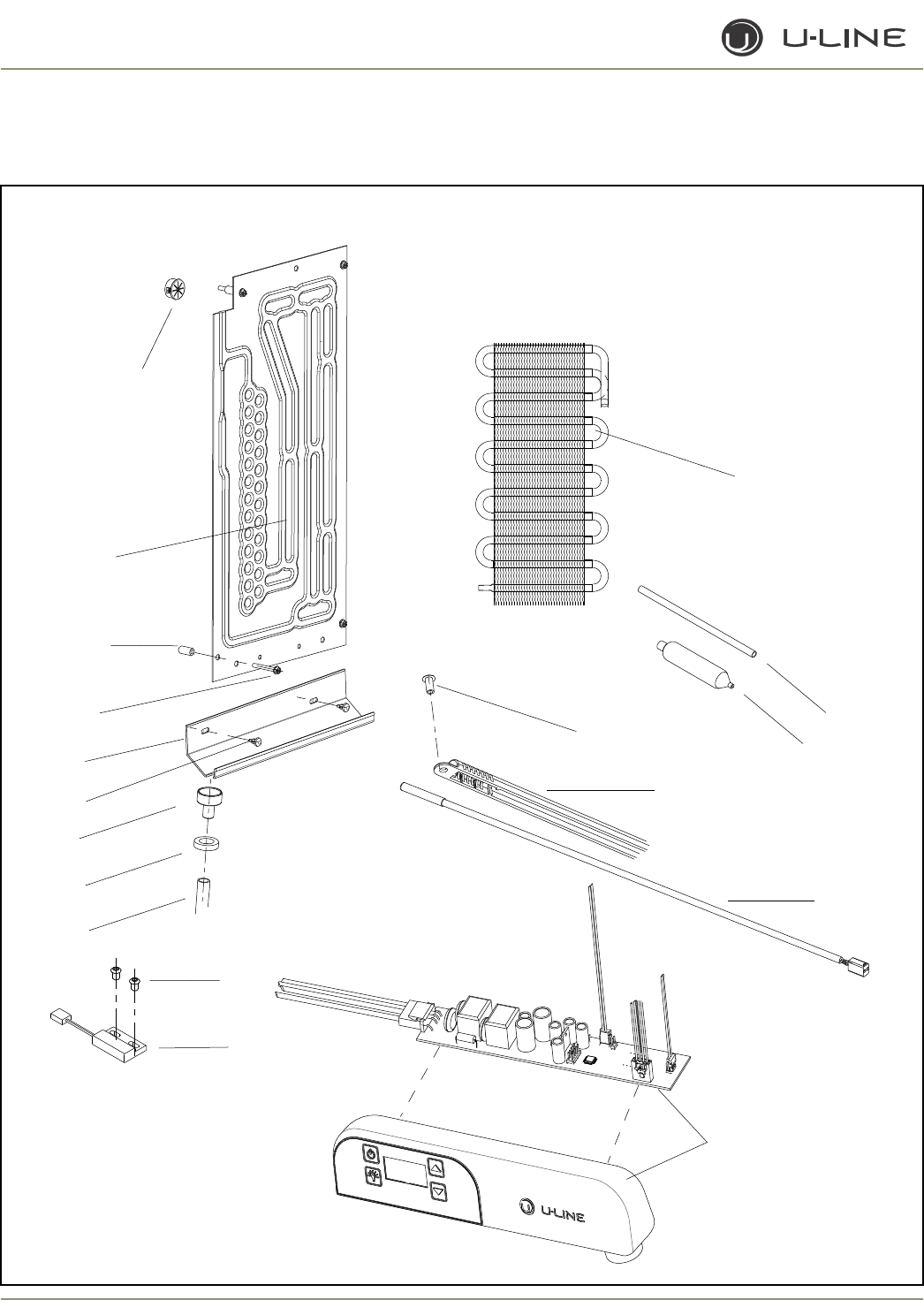
4-84
Section 4 - Parts
1115WC (2 of 2)
2
3
4
5
6
7
10
9
11
12
13
14
16
8
1
15
17
18

4-85
Section 4 - Parts
Item Part No. Part No. Description
Black Stainless Steel
1 2223-S 2223-S Condenser Assembly**
2 2800 2800 Process tube
3 2694 2694 Dryer, R-134A
4 31434-1 31434-1 Rivet, thermistor cover White
31434-2 31434-2 Rivet, thermistor cover Black
5 26091 26091 Cover, thermistor White
26091-02 26091-02 Cover, thermistor Black
6 68073 68073 Thermistor, quick connect white
7 26059 26059 Control Display Assembly White
26059-03 26059-03 Control Display Assembly Black
8 66010 66010 Reed switch
9 41863 41863 Rivet, reed switch
10 31594 31594 Drain tube
11 31578 31578 Washer, drain tube White
31578-02 31579-02 Washer, drain tube Black
12 11508 11508 Drain cup White
11508-02 11508-02 Drain cup Black
13 21012-WHT 21012-WHT Rivet White
21012-BLK 21012-BLK Rivet Black
14 31391-2 31391-2 Drain trough White
31391-10 31391-10 Drain trough Black
15 41855 41855 Screw Silver
41855-02 41855-02 Screw Black
16 31213 31213 Spacer
17 2649-S 2649-S Evaporator White **
2649-02-S 2649-02-S Evaporator Black **
18 31386-02 31386-02 Bushing White
31386 31386 Bushing Black
**Includes Dryer & Process Tube
1115WC (2 of 2
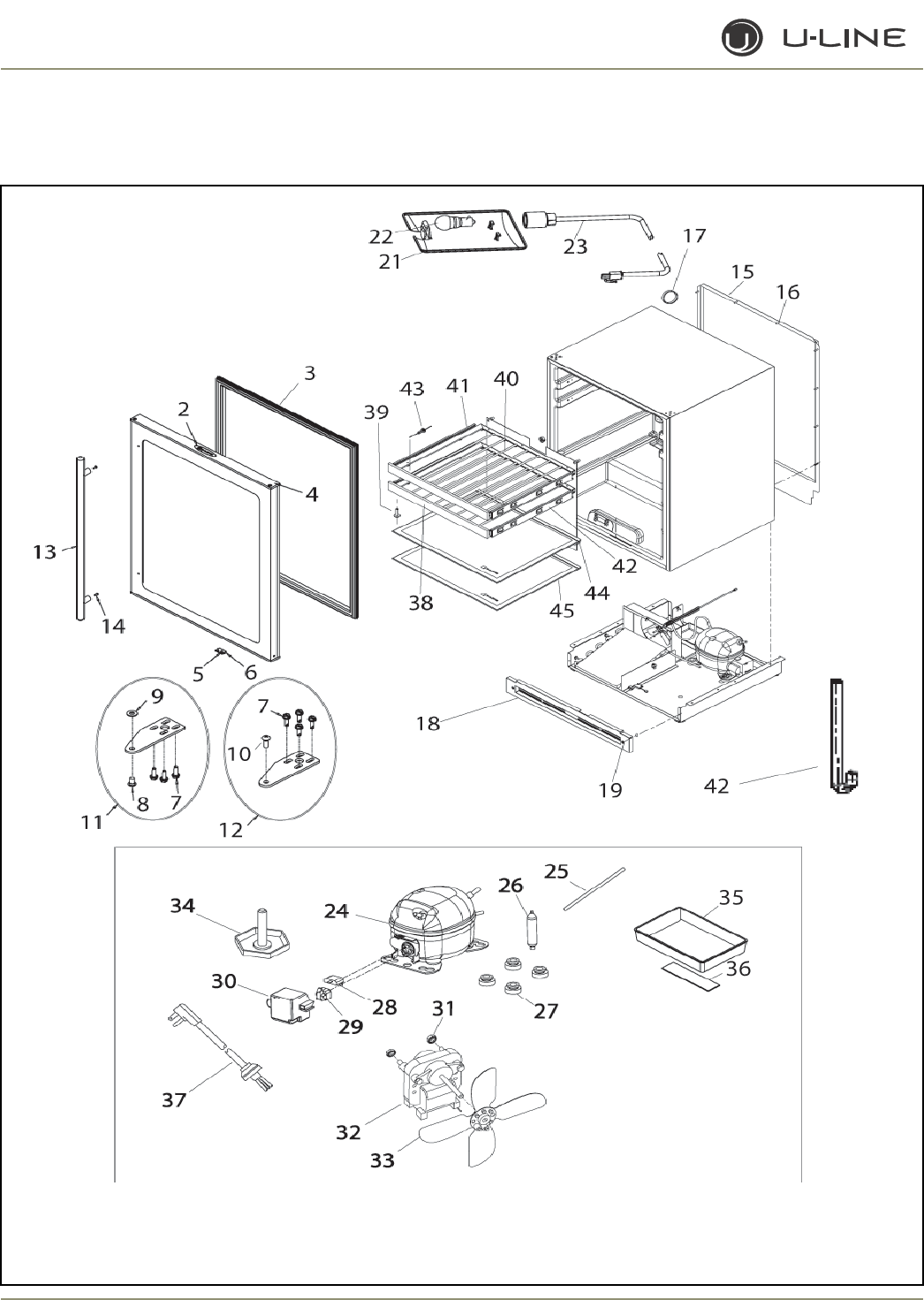
4-86
Section 4 - Parts
1175BEV (1 OF 2)

4-87
Section 4 - Parts
Item Part No. Description
1 80-17069-03-G Door Assembly, FieldReversable
2 23051-01 Nameplate (included with #1)
3 31493-4-BLK Gasket (included with #1)
4 31447-BLK Hole plug (included with #1)
5 20031 Screw (included with #1)
6 66016 Magnet (included with #1)
7 20042-BLK Screw, hinge (included with hinge assembly)
8 41747-SSB Pivot screw, bottom (included with hinge assembly)
9 21017 Washer (included with hinge assembly)
10 41785-SSB Pivot screw, top (included with hinge assembly)
11 14136-SB Hinge Assembly, bottom
12 14136-ST Hinge Assembly, top
13 23050-01 Towel bar handle (accessory only)
15 11769 Back panel
16 41342 Screw, back panel
17 42125 Hole cover, solid
18 80-29094-01 Grille
19 20033-BLK Screw (included with grille)
21 11859 Lens, light housing
22 31317 Light bulb, 10W, 120V
23 2891-01 Light Socket Assembly
24 5400-S Compressor, EM130HER
25 2800 Process tube (included with #24)
26 2694 Dryer (included with #24)
27 31021 Grommet (included with #24)
28 5411 Overload (included with #24)
29 5412 Relay (included with #24)
30 5400-CAP Cap (included with #24)
31 41787 Nut (included with #32)
32 5263-S Fan motor, condenser
33 5188 Fan blade, plastic
34 41319 Foot, leveler, 1/4-20
35 31550-1-S Drain pan
36 31664 Tape (included with drain pan)
37 2938-2 Power cord
38 11988-03 Wood front
39 4816 Screw
40 18066 Wine rack
41 23026-03 Slide Assembly (set of 2)
42 28004 Drain tube
43 42106 Screw, wood
44 25032-2 Edge trim, rear
45 40010-04 Glass shelf
Not
Shown 26147 Door Spacer, for Field Reversable Doors
1175BEV (1 OF 2)
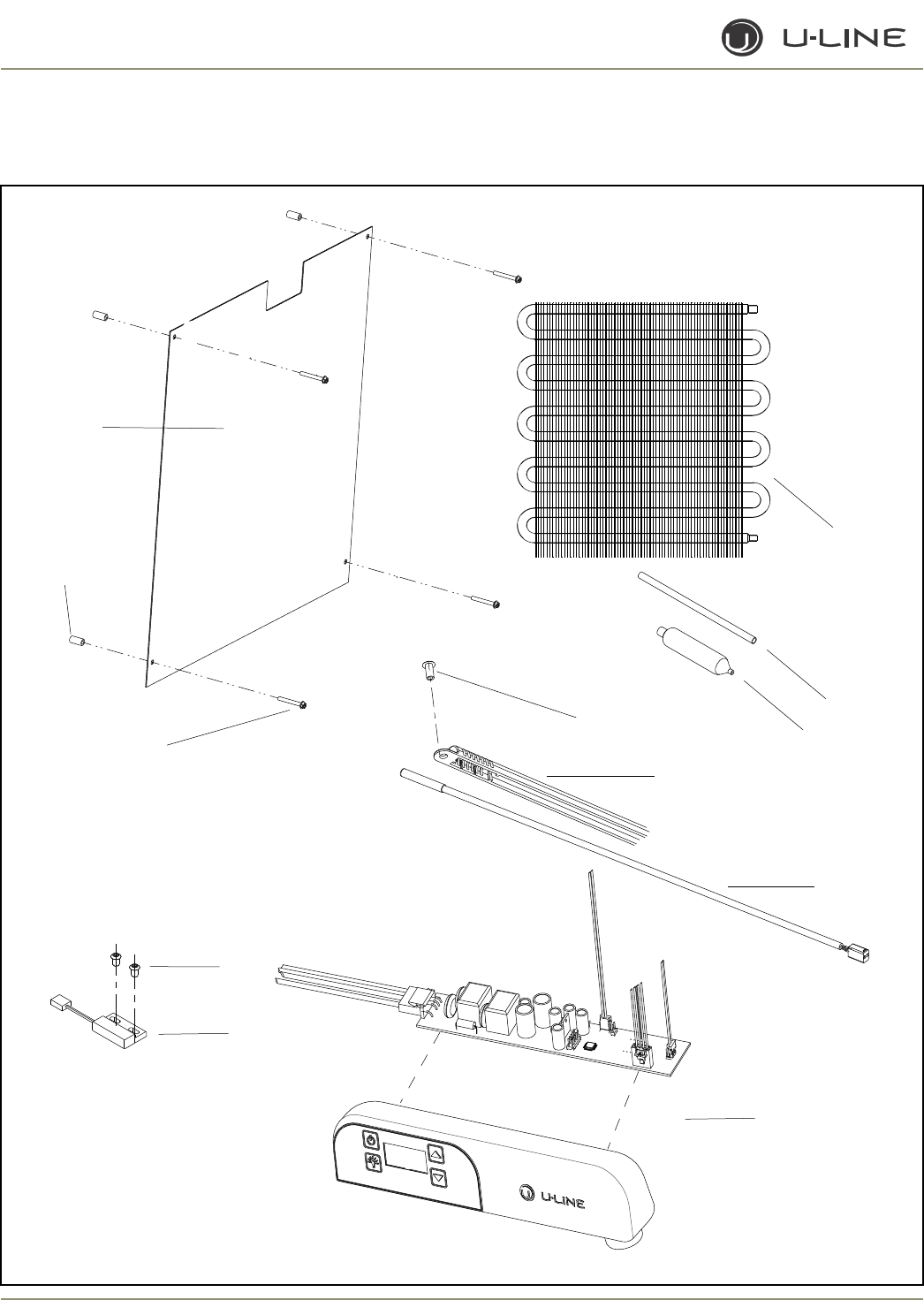
4-88
Section 4 - Parts
2
3
4
5
6
9
8
11
12
1
7
10
1175BEV (2 OF 2)

4-89
Section 4 - Parts
Item Part No. Description
1 1951-S Condenser Assembly **
2 2800 Process tube
3 2694 Dryer
4 31434-1 Rivet, thermostat cover White
31434-2 Rivet, thermostat cover Black
5 26091 Cover, thermistor White
26091-03 Cover, thermistor Black
6 68073 Thermistor, quick connect white
7 26058 Control Display Assembly White
26059-03 Control Display Assembly Black
8 66010 Reed switch
9 20026 Screw, reed switch
10 41855 Screw, evaporator SS
41855-02 Screw, evaporator Black
11 31213 Spacer, evaporator
12 2186-S Evaporator Assembly White **
2186-02-S Evaporator Assembly Black **
** Includes dryer & Process Tube
1175BEV (2 of 2)
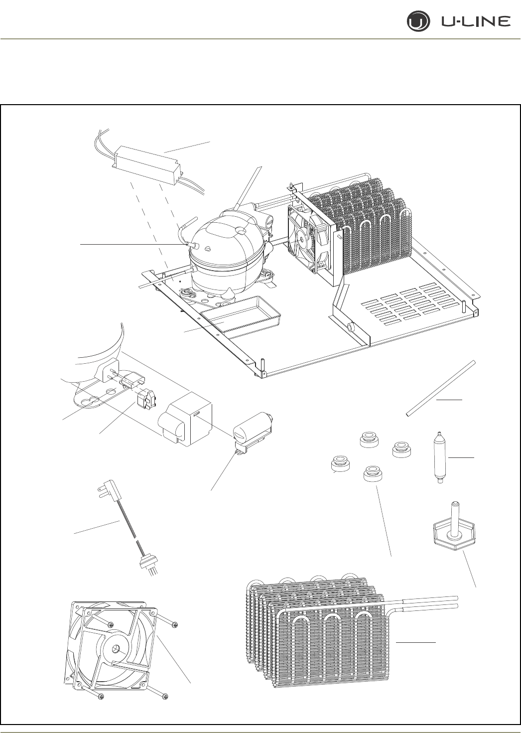
4-90
Section 4 - Parts
2
3
4
5
6
1
7
8
9
10
11
12
13
ADA24R (1 0F 2)
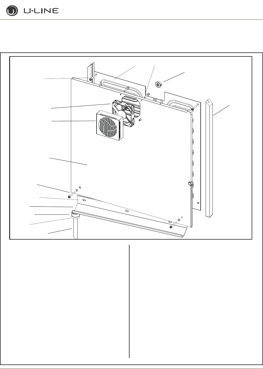
4-91
Section 4 - Parts
ADA24R (1 0F 2)
14
15
16
17
18
19
20
21
22
23
24 25
27
26
Item Part No. Description
1 70077-S Compressor**
2 68103 Transformer
3 2819 Process Tube*
4 2694 Drier*
5 41319 Leveling Leg
6 31021 Grommet*
7 74021-S Condenser**
8 67009 DC Condenser Fan
(includes fan blade)
9 2938-2 Power Cord
10 71013 Capacitor*
11 71010 Relay*
12 71009 Overload*
13 31550-1-S Drain Pan
14 31579 Drain Tube
* Included with the compressor
Item Part No. Description
15 31578 Foam Washer
16 11508 Drain Cup
17 31391-3 Drain Trough
18 21012-WHT Rivet
19 41855-01 Screw
20 14308-02 Evaporator Cover
21 26117-02 Evap Fan Cover
22 67005 DC Evaporator Fan
(includes fan blade)
23 41855 Screw
24 2333-S Evaporator **
25 41405 Screw
26 31386-02 Bushing
27 38036 Foam Spacer
** Includes drier and process tube
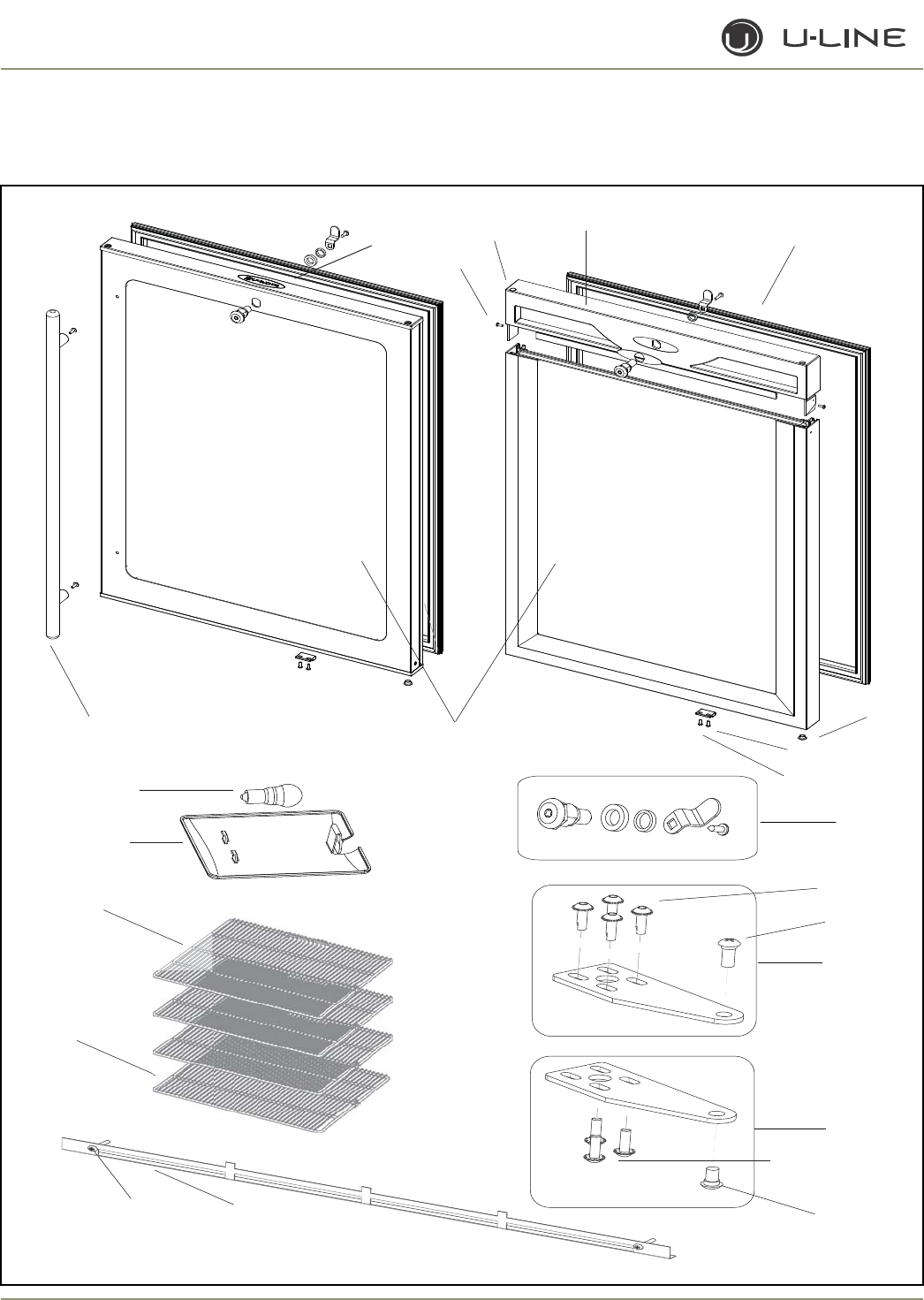
4-92
Section 4 - Parts
ADA24R (2 0F 2)
2
4
1
1
23
45
6
7
8
9
10
11
12
13
14
15
16
17
18
19
11
21
20
22
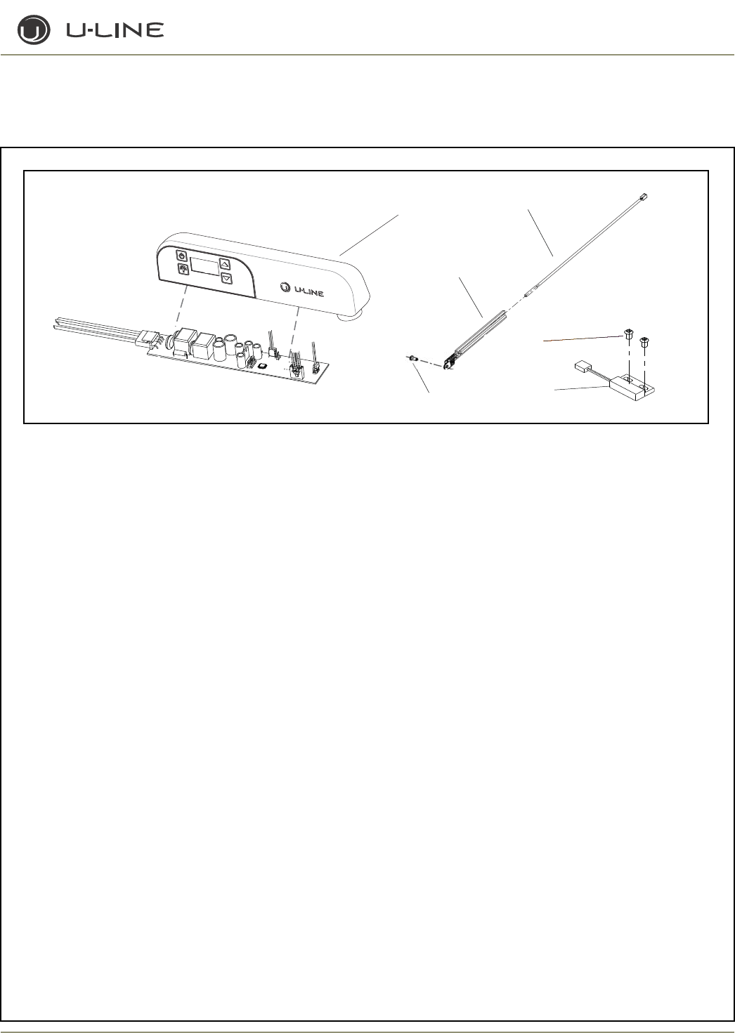
4-93
Section 4 - Parts
Item Part No. Part No. Description
Black Stainless Steel
1 80-17119-01 80-17121-01 Glass Door Right Hand Hinge
N/A 80-17121-02 Glass Door Left Hand Hinge
80-17118-01 80-17120-01 Solid Door Right Hand Hinge
N/A 80-17120-02 Solid Door Leftt Hand Hinge
2 23051-01 23051-01 Nameplate
3 41604 N/A Handle Screw
4 31447-BLK 31447-BLK Hole Plug Black
5 26142-01 N/A Solid Door Handle with lock
6 31493-4-BLK 31493-4-blk Door Gasket
7 31309-BLK 21017 Hole Plug/Washer
8 66016 66016 Heavy Duty Magnet
9 20031 20031 Magnet Screws
10 23000-S 23000-S Lock Assembly
11 20042-BLK 20042-BLK Hinge Screws
12 41785-SSB 41785-SSB Top Pivot Screw
13 11849-ST-BLK 14136-ST Top Hinge Assembly (includes screws)
14 11849-SB-BLK 14136-SB Bottom Hinge Assembly (includes screws)
15 41747-SSB 41747-SSB Bottom Pivot Screw
16 80-29018-00 80-29018-00 Grille Assembly Black (includes screws)
17 20033-BLK 20033-BLK Grille Screw
18 18089-02 18089-02 Wire Shelf Bottom
19 18090-01 18090-01 Wire Shelf
20 11859 11859 Light Cover
21 31317 31317 Light Bulb
22 N/A 23011-03 Stainless Steel Handle (accessory only)
23 26059-02 26059-02 Control Assembly
24 26091 26091 Thermistor Cover
25 68073 68073 Thermistor
26 20026 20026 Screws Reed Switch
27 66010 66010 Reed Switch
28 21012-WHT 21012-WHT Push Rivet
ADA24R (2 0F 2)
23
24
25
26
28 27
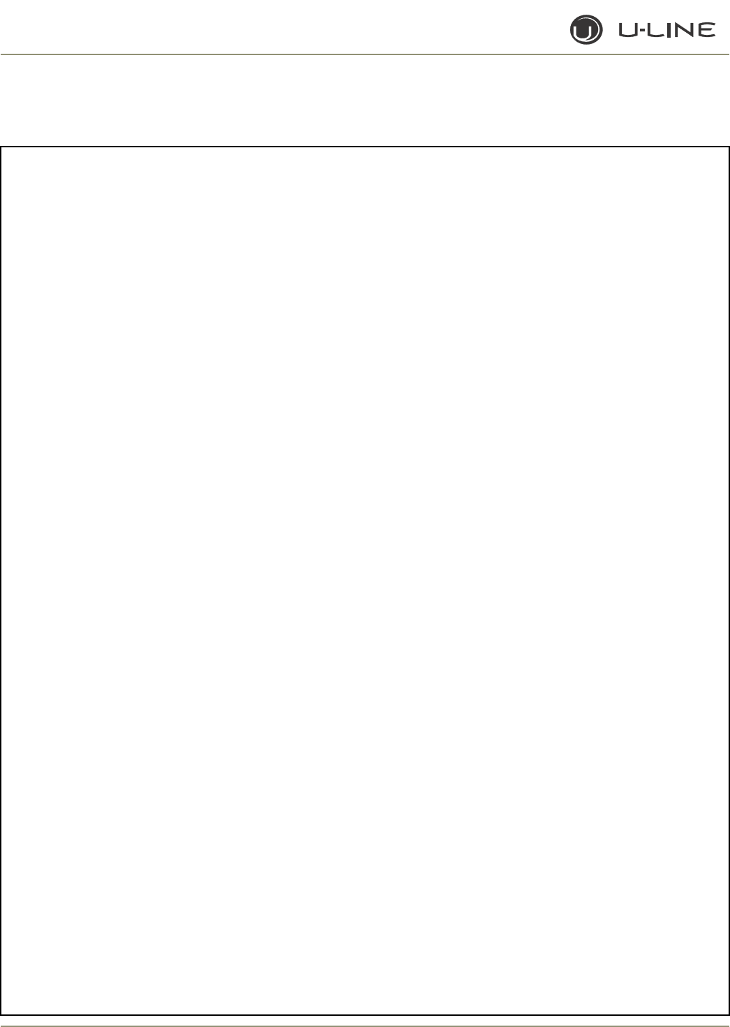
4-94
Section 4 - Parts
This page intentionally left blank.
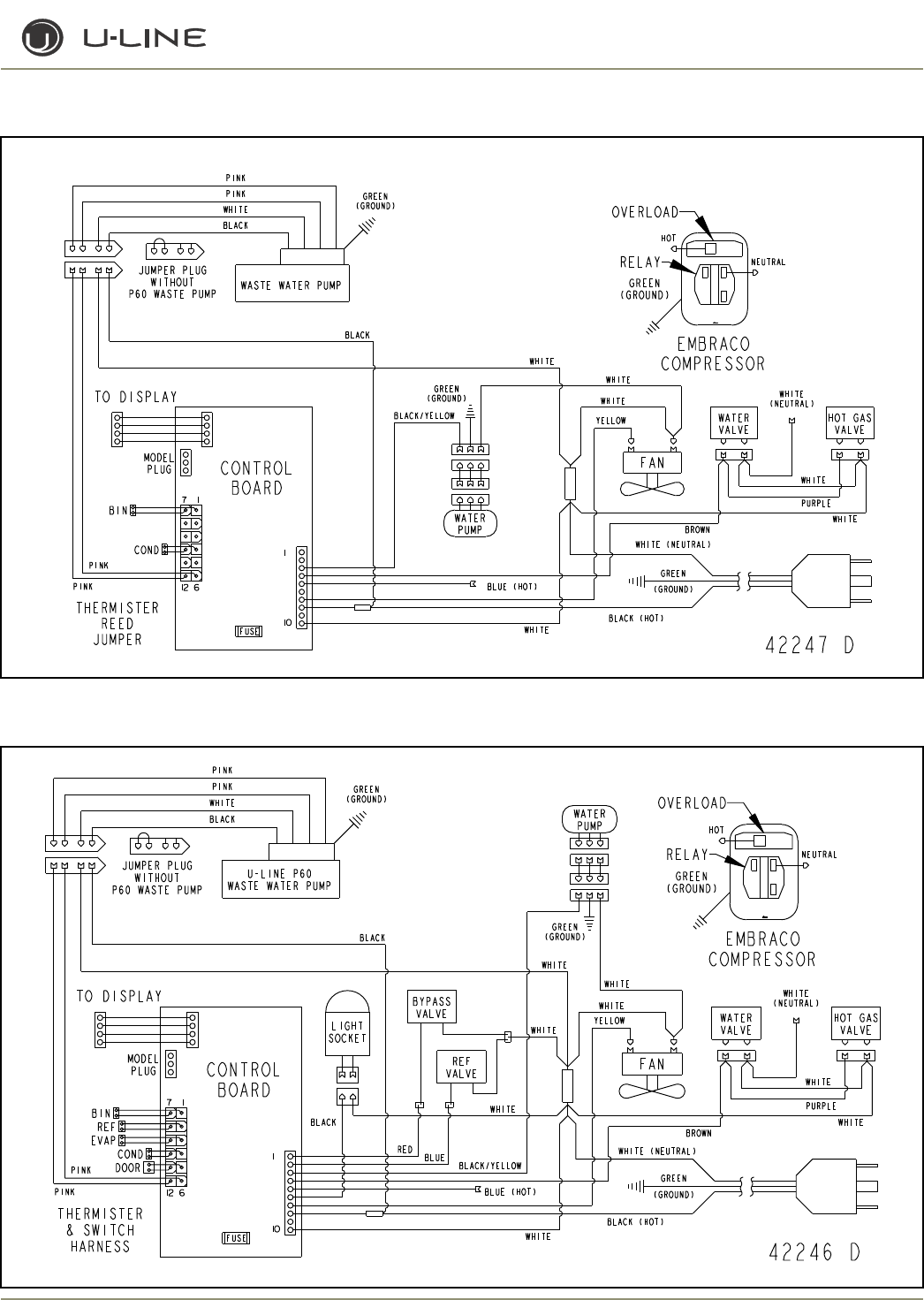
5-1
Section 5 - Wiring Diagrams
WATER
PUMP
Lawrence
BIN
COND
12 6
FUSE
42247 D
GREEN
BLACK (HOT)
WHITE (NEUTRAL)
1
10
CONTROL
BOARD
MODEL
PLUG
7 1
THERMISTER
REED
JUMPER
(GROUND)
TO DISPLAY
WASTE WATER PUMP
JUMPER PLUG
WITHOUT
P60 WASTE PUMP
GREEN
(GROUND)
BLACK
WHITE
PINK
PINK
PINK
PINK
FAN
HOT GAS
VALVE
WATER
VALVE
GREEN
(GROUND)
WHITE
WHITE
WHITE
(NEUTRAL)
WHITE
WHITE
BLUE (HOT)
YELLOW
BLACK/YELLOW
PURPLE
BROWN
WHITE
WHITE
BLACK
OVERLOAD
NEUTRAL
HOT
RELAY
EMBRACO
COMPRESSOR
GREEN
(GROUND)
CLR2160
CLRCO2175
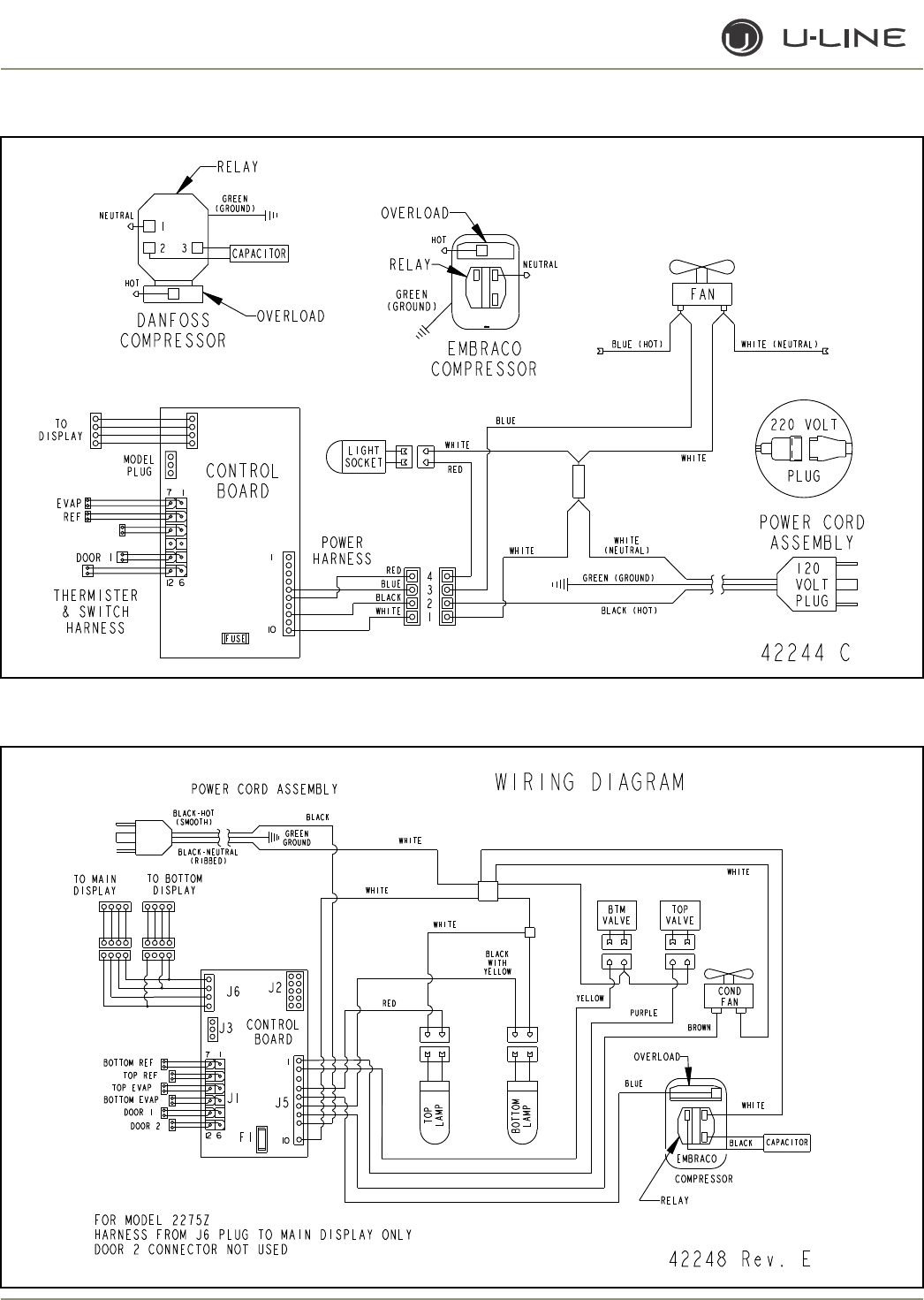
5-2
Section 5 - Wiring Diagrams
WIRING DIAGRAM
42248 Rev. E
TOP
LAMP
BOTTOM
LAMP
POWER CORD ASSEMBLY
GREEN
GROUND
BLACK-HOT
(SMOOTH)
BLACK-NEUTRAL
(RIBBED)
EMBRACO
WHITE
COMPRESSOR
OVERLOAD
BROWN
BLUE
PURPLE
COND
FAN
RELAY
BLACK CAPACITOR
BLACK
WHITE
WHITE
WHITE
BTM
VALVE
TOP
VALVE
YELLOW
RED
WHITE
BLACK
WITH
YELLOW
TO BOTTOM
DISPLAY
7 1
J6
BOTTOM REF
12 6
1
TOP REF
TOP EVAP
BOTTOM EVAP
DOOR 1
DOOR 2
J5
J3
J1
10
F1
J2
TO MAIN
DISPLAY
CONTROL
BOARD
FOR MODEL 2275Z
HARNESS FROM J6 PLUG TO MAIN DISPLAY ONLY
DOOR 2 CONNECTOR NOT USED
2115R, 2115WC, 2175R, 2175WC, 2175BEV
2275DWRWS, 2275ZWC
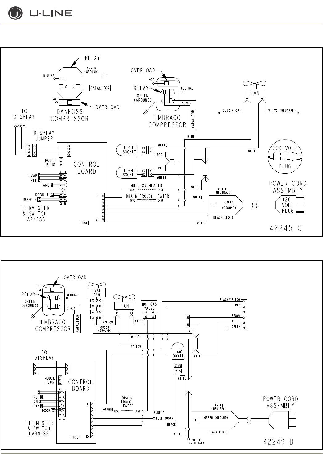
5-3
Section 5 - Wiring Diagrams
2175DWRR, 2275DWRR
2175RF
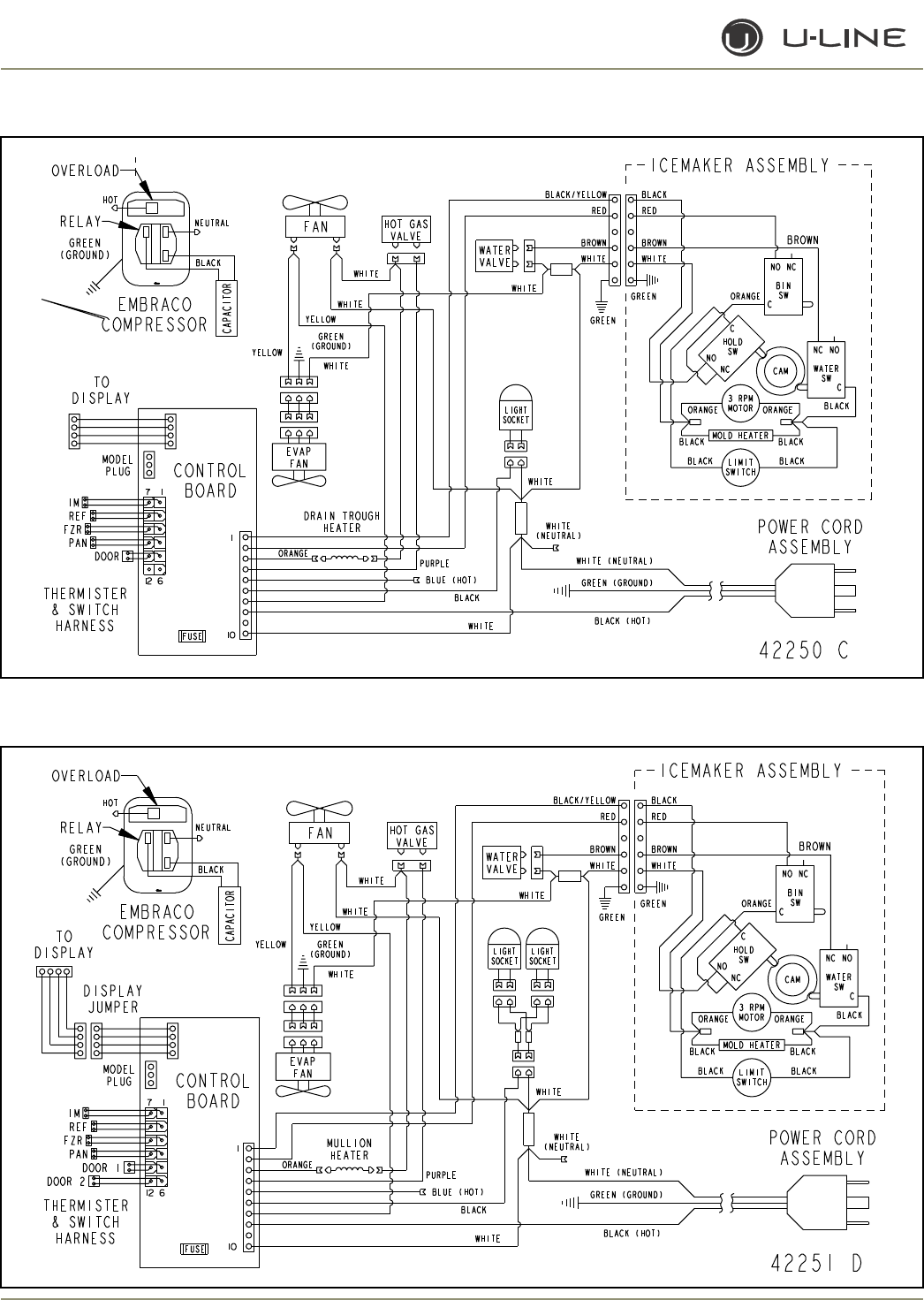
5-4
Section 5 - Wiring Diagrams
CO2175F
CO2175DWR, CO2275DWR
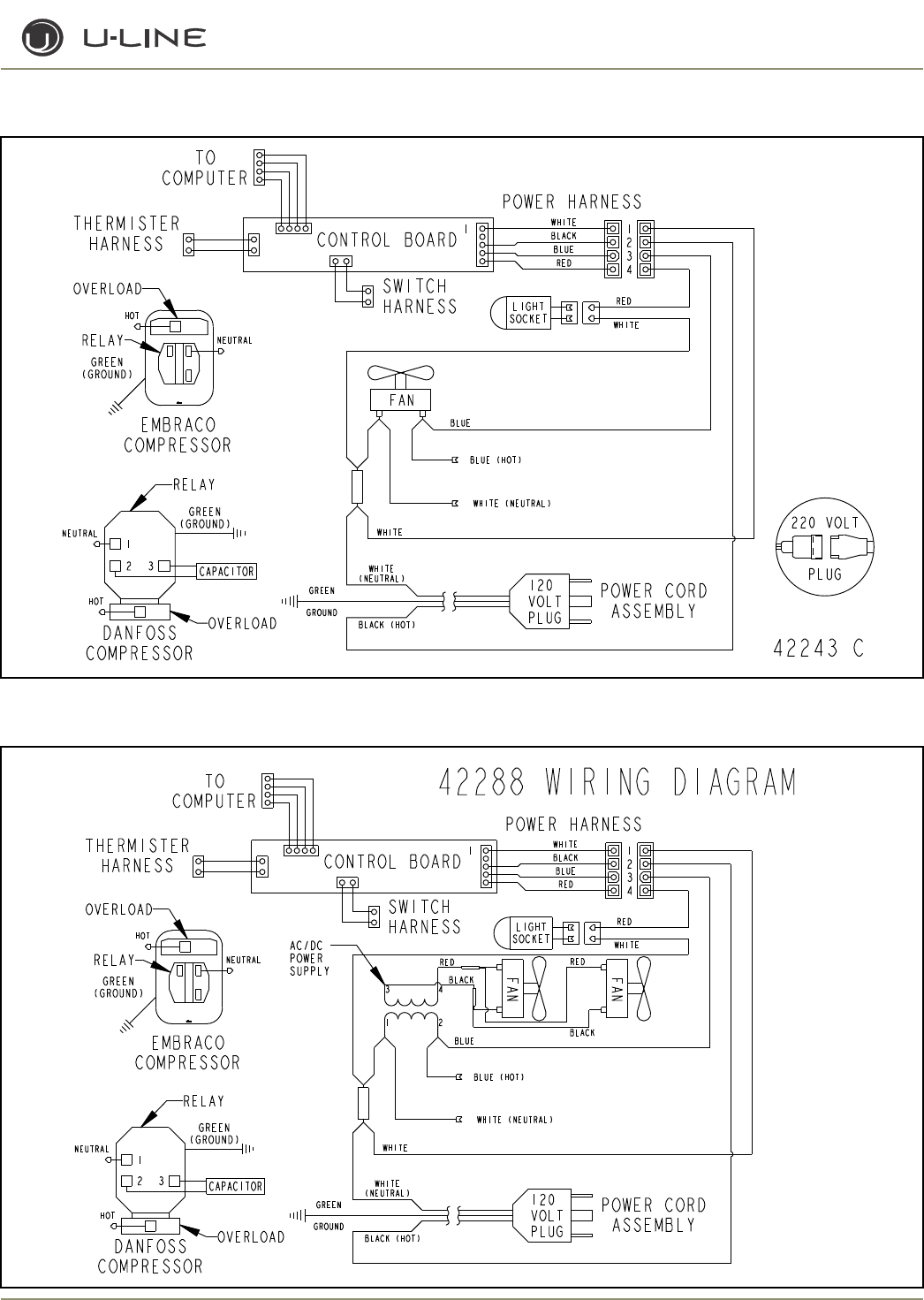
5-5
Section 5 - Wiring Diagrams
1175R, 1115R, 1175WC, 1115WC, 1175BEV
ADA24R

5-6
Section 5 - Wiring Diagrams
This page intentionally left blank.

For Every Room There is a U-Line ®
ABOUT U-LINE
Building on 45 years, U-Line has captivated those with an appreciation for the finer things with exceptional
design, inspired innovations and attention to even the smallest details.
U-Line is synonymous with premium built-in undercounter ice making, refrigeration and wine storage appli-
ances, the U-Line Corporation is committed to luxury under the counter. U-Line is known and respected for
unwavering dedication to product innovation, quality and selection. A bold and broad line of models is the
product of visionaries in the pursuit of distinctive living environments in the kitchen and spaces beyond.
In 1962, Henry Uihlein founded U-Line Corporation as an outgrowth of Ben-Hur Freezer Company and was
the first to develop and patent an automatic stand-alone undercounter residential ice maker. His foresight and
determination to develop new ideas and to succeed when there were no clear guidelines or solutions are evi-
dent today. The Milwaukee, Wisconsin based family operated business provides continuity and vision from
which innovations continue to be born.
Going forward, U-Line will continue offering best-in-class products that build on the company's numerous pat-
ents and world firsts to guide the undercounter industry in realizing its unlimited potential.
GENERAL INQUIRIES:
U-Line Corporation
P.O. Box 245040
Milwaukee, Wisconsin 53224-9540 U.S.A.
Phone (414) 354-0300
FAX (414) 354-7905
Email: sales@u-line.com
www.u-line.com
SERVICE ASSISTANCE:
Phone (800) 779-2547
FAX (414) 354-5696
Email: onlineservice@u-line.com
www.u-lineservice.com
PARTS ASSISTANCE:
E-mail: onlineparts@u-line.com
PRODUCT INFORMATION
Installation Guides with complete installation information, Custom Wood Panel Size Specifications & Installa-
tion Instructions, CAD Drawings, Use and Care Guides, Specifications & Feature Benefits are available for view-
ing and download on-line at www.u-line.com/specs/.
©2010 U-Line Corporation
Publication No. 30131 01/2010 Rev. F
