U MEDIA Communications WRT372U 2.4GHz Wireless 802.11n(DRAFT) Router User Manual WRT 372U FCC
U-MEDIA Communications, Inc. 2.4GHz Wireless 802.11n(DRAFT) Router WRT 372U FCC
UserManual.wiki
>
U MEDIA Communications
>
WRT372U User Manual
Manual
Navigation menu
Upload a User Manual
Namespaces
Wiki Guide
HTML
PDF
Info
Views
User Manual
Discussion / Help
Navigation

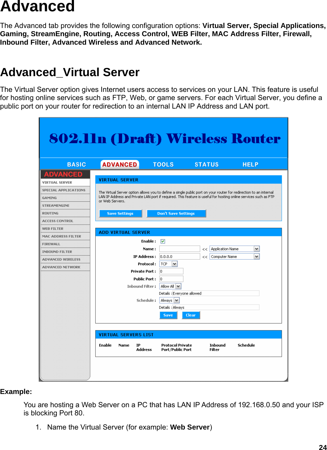
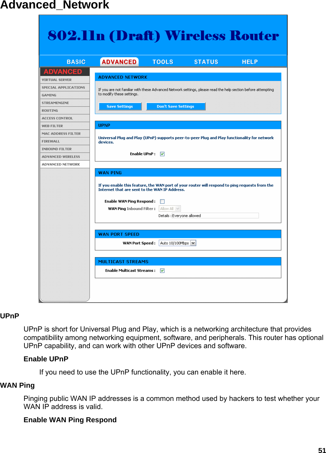
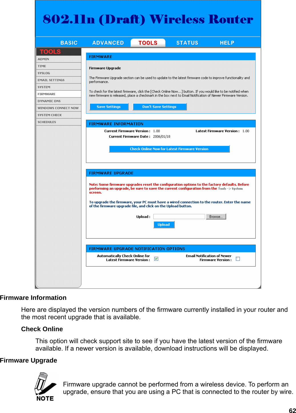
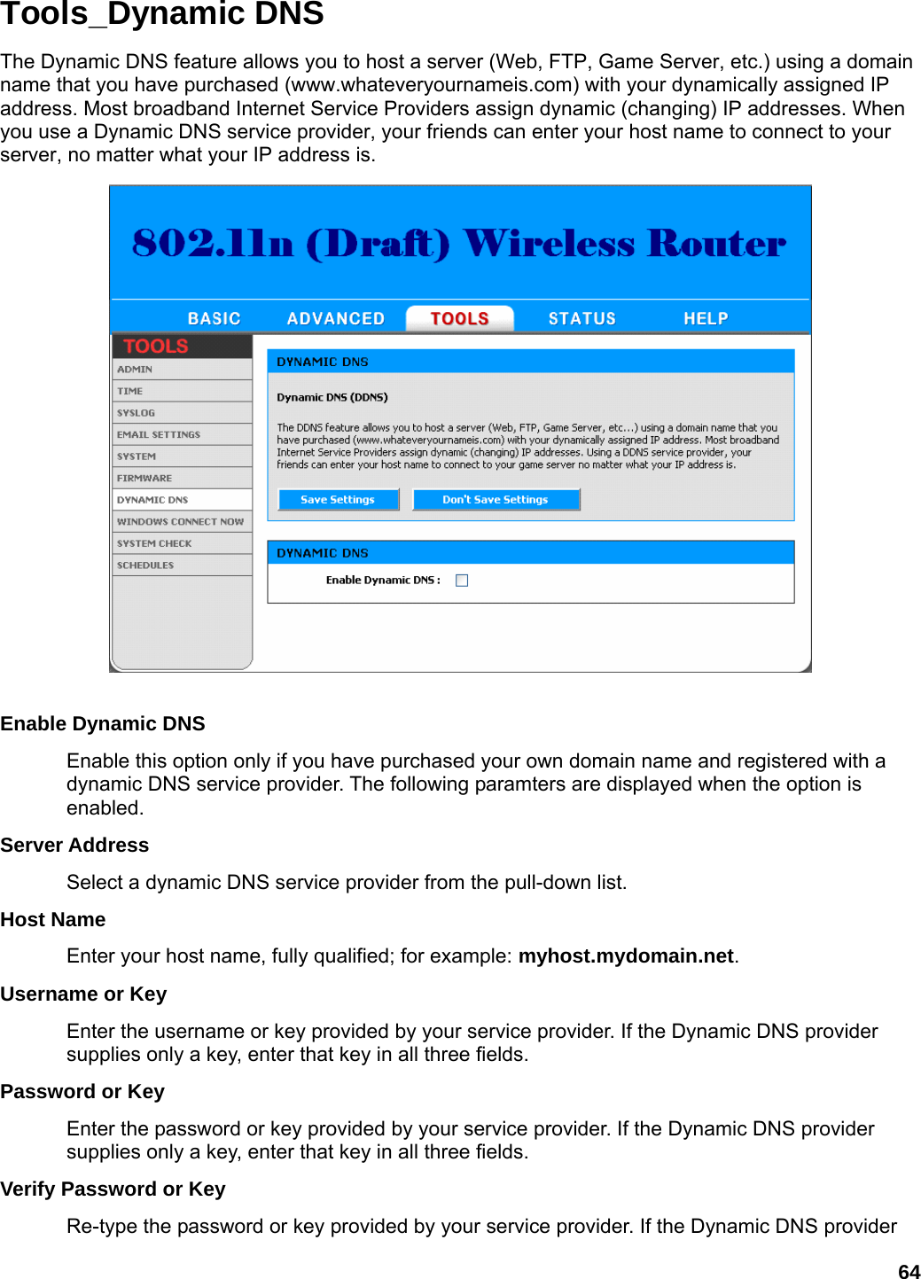
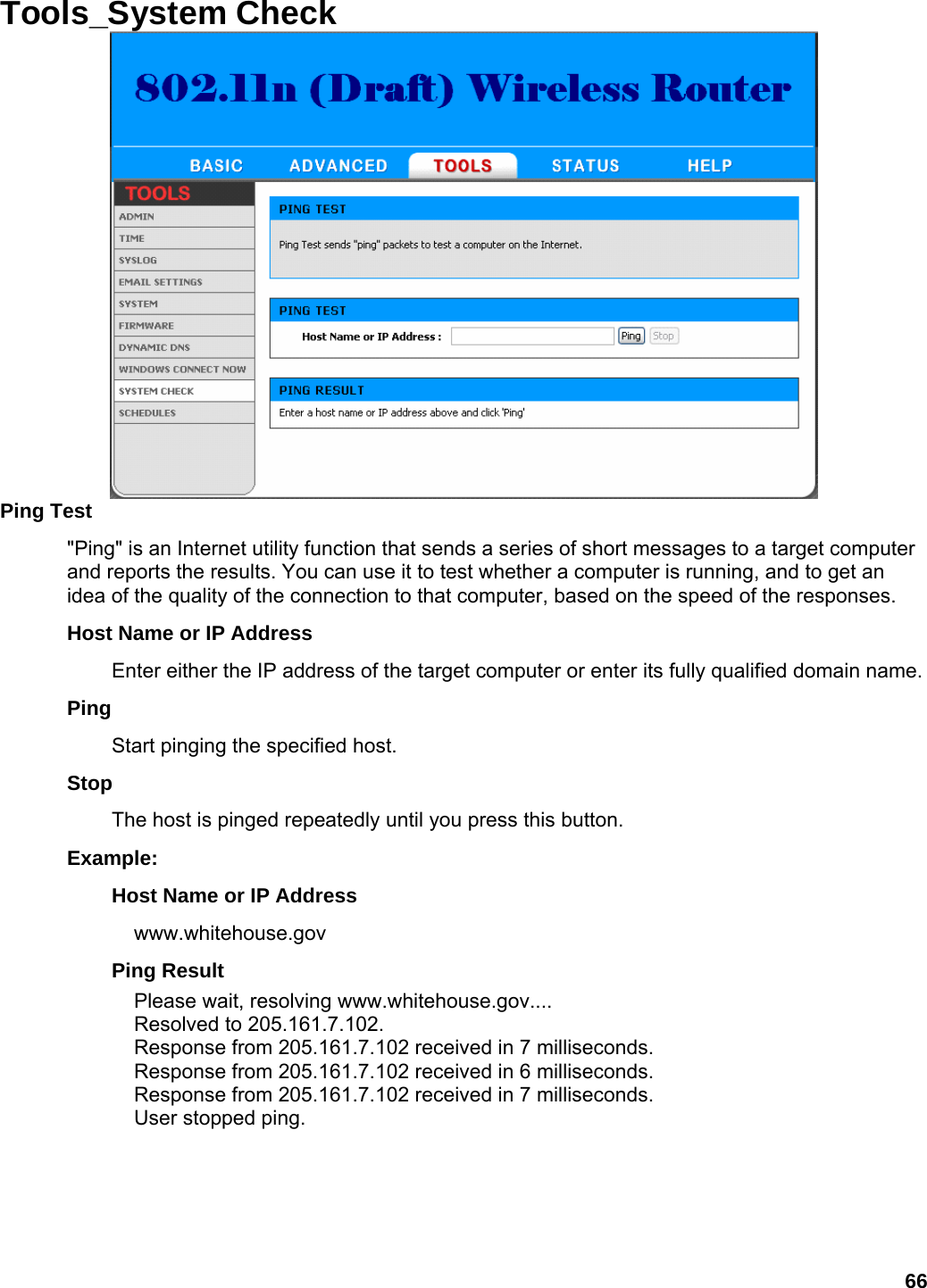
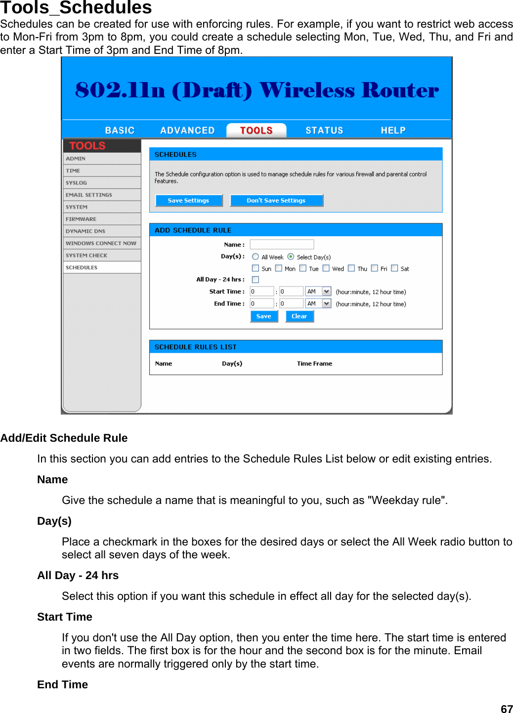
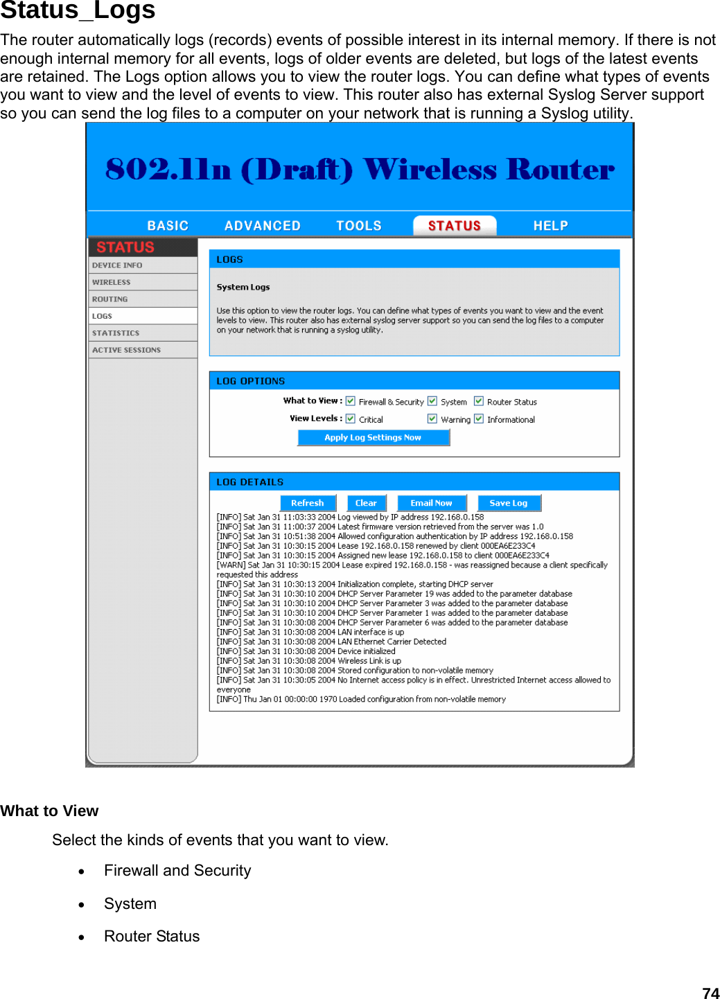
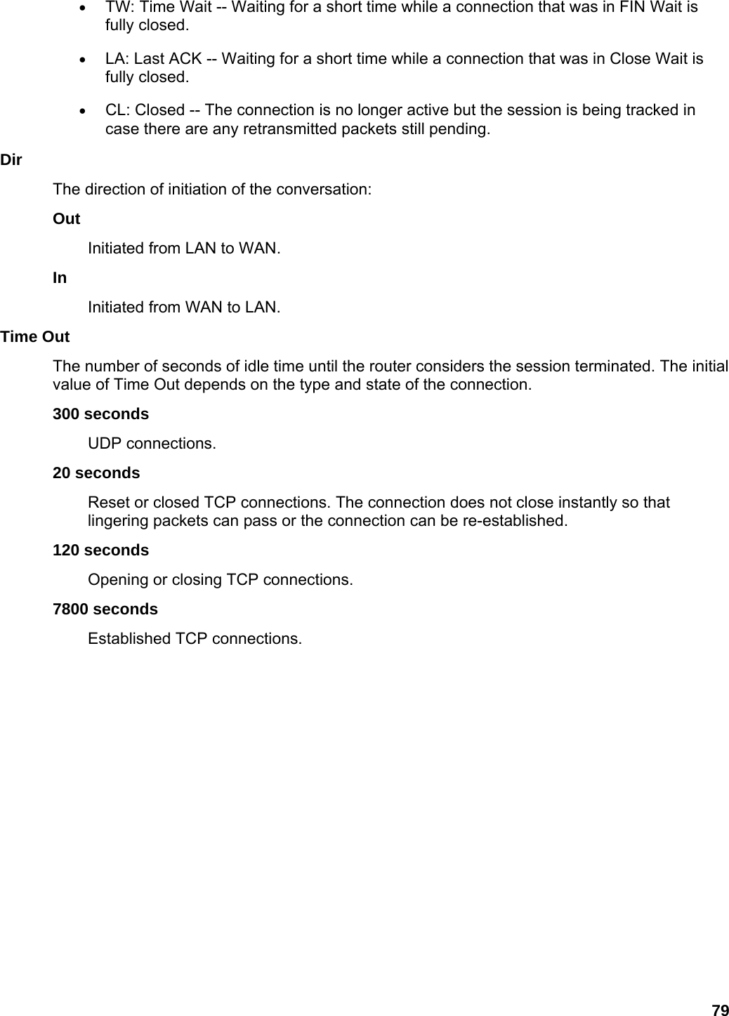
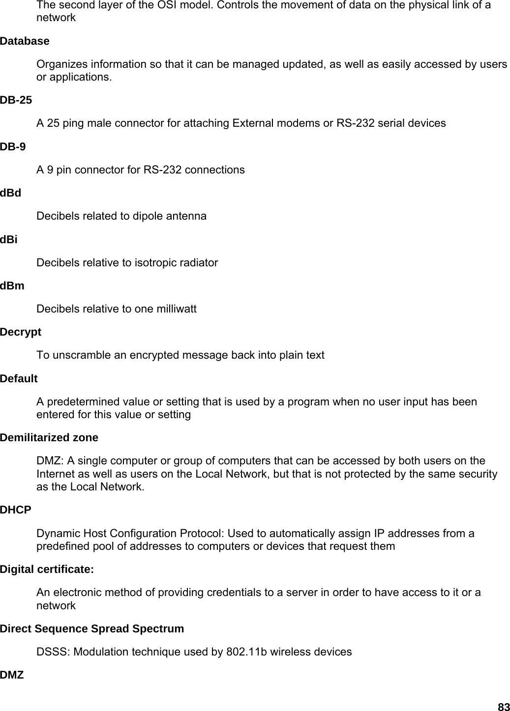
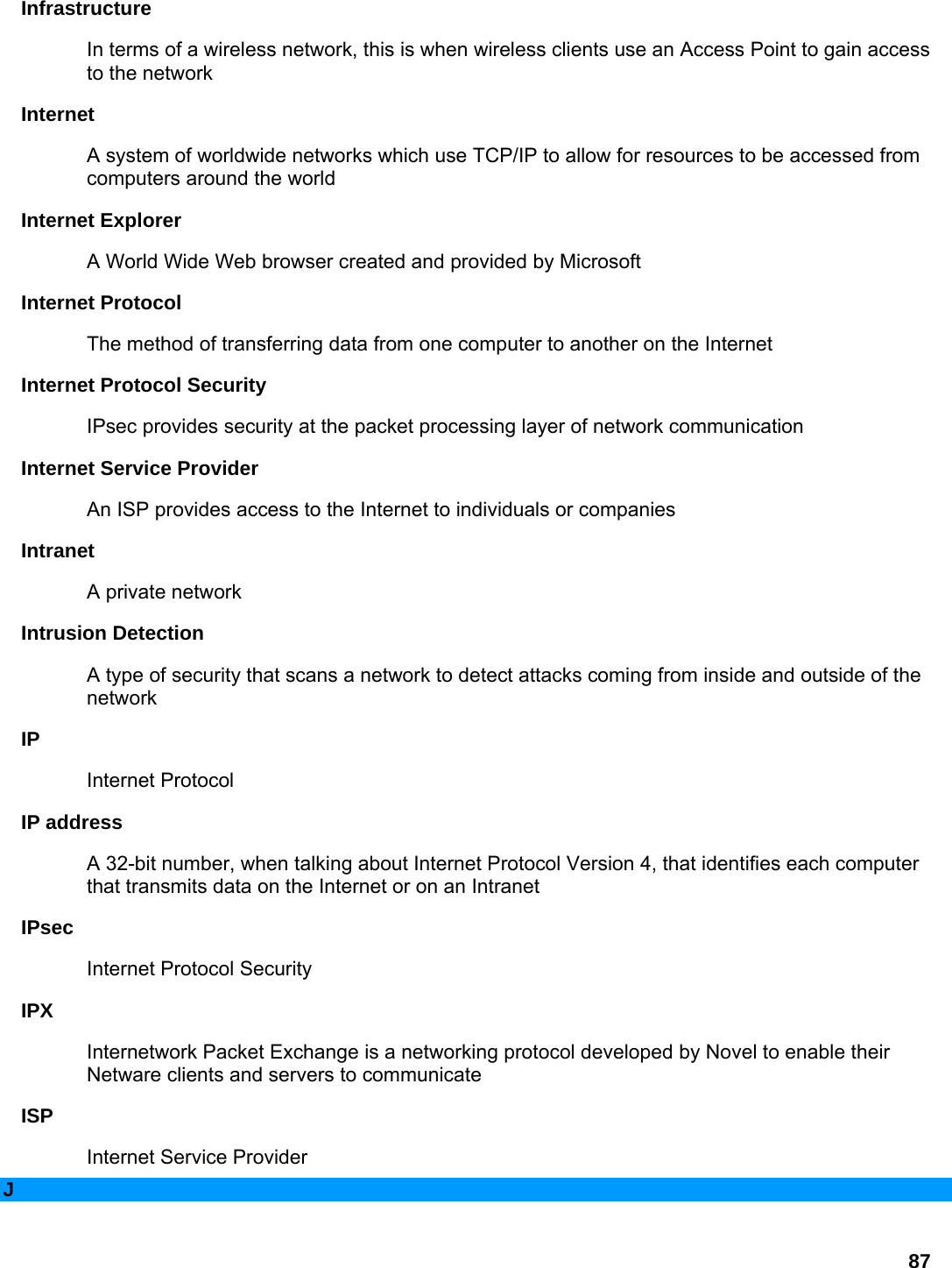
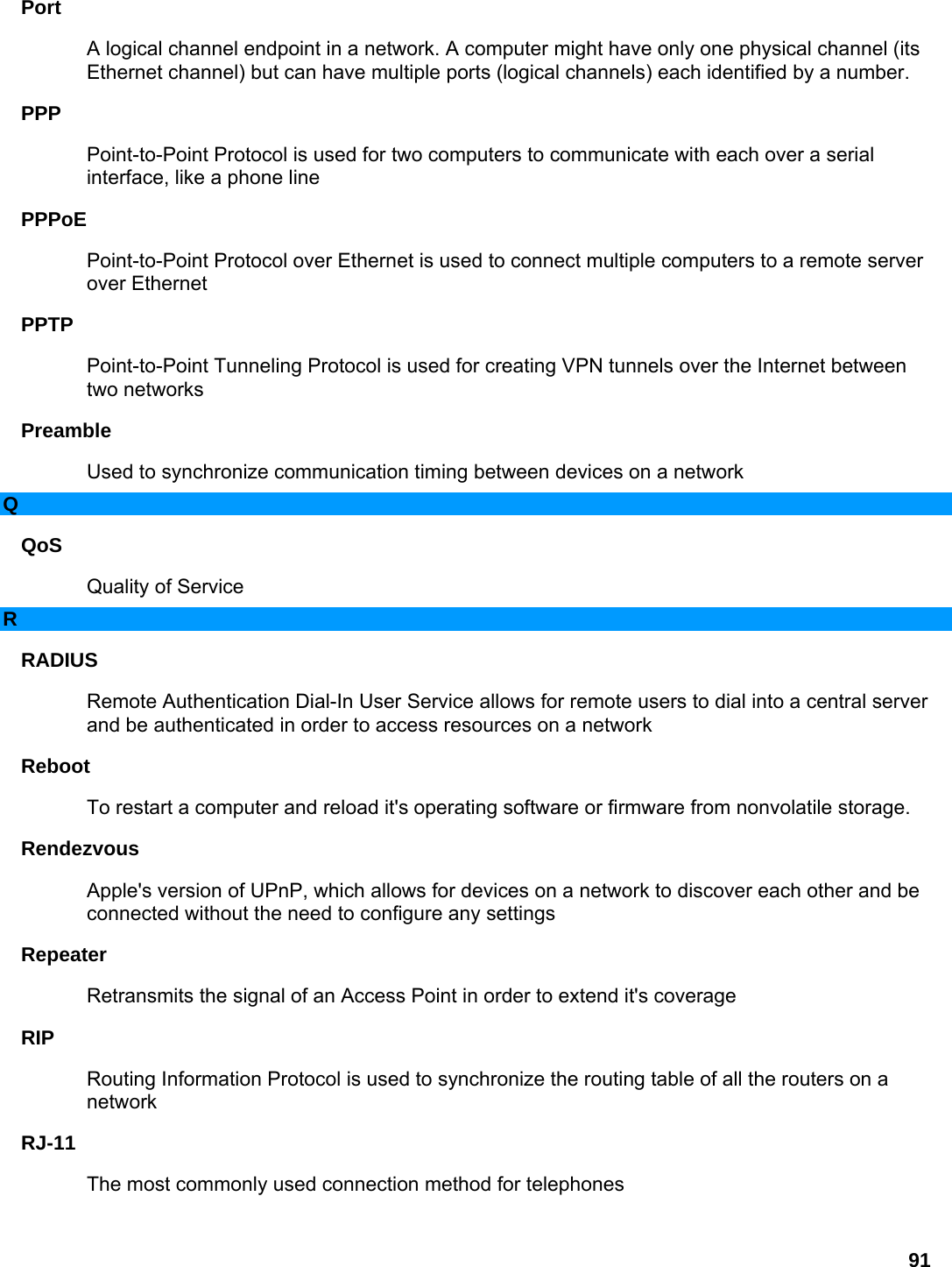
![25 2. Enter the IP Address of the machine on your LAN (for example: 192.168.0.50 3. Enter the Private Port as [80] 4. Enter the Public Port as [8888] 5. Select the Protocol (for example TCP). 6. Ensure the schedule is set to Always 7. Click Save to add the settings to the Virtual Servers List 8. Repeat these steps for each Virtual Server Rule you wish to add. After the list is complete, click Save Settings at the top of the page. With this Virtual Server entry, all Internet traffic on Port 8888 will be redirected to your internal web server on port 80 at IP Address 192.168.0.50. Virtual Server Parameters Name Assign a meaningful name to the virtual server, for example Web Server. Several well-known types of virtual server are available from the "Application Name" drop-down list. Selecting one of these entries fills some of the remaining parameters with standard values for that type of server. IP Address The IP address of the system on your internal network that will provide the virtual service, for example 192.168.0.50. You can select a computer from the list of DHCP clients in the "Computer Name" drop-down menu, or you can manually enter the IP address of the server computer. Protocol Select the protocol used by the service. The common choices -- UDP, TCP, and both UDP and TCP -- can be selected from the drop-down menu. To specify any other protocol, select "Other" from the list, then enter the corresponding protocol number ( as assigned by the IANA) in the Protocol box. Private Port The port that will be used on your internal network. Public Port The port that will be accessed from the Internet. Inbound Filter Select a filter that controls access as needed for this virtual server. If you do not see the filter you need in the list of filters, go to the Advanced → Inbound Filter screen and create a new filter. Schedule Select a schedule for when the service will be enabled. If you do not see the schedule you need in the list of schedules, go to the Tools → Schedules screen and create a new schedule.](https://usermanual.wiki/U-MEDIA-Communications/WRT372U/User-Guide-684942-Page-26.png)