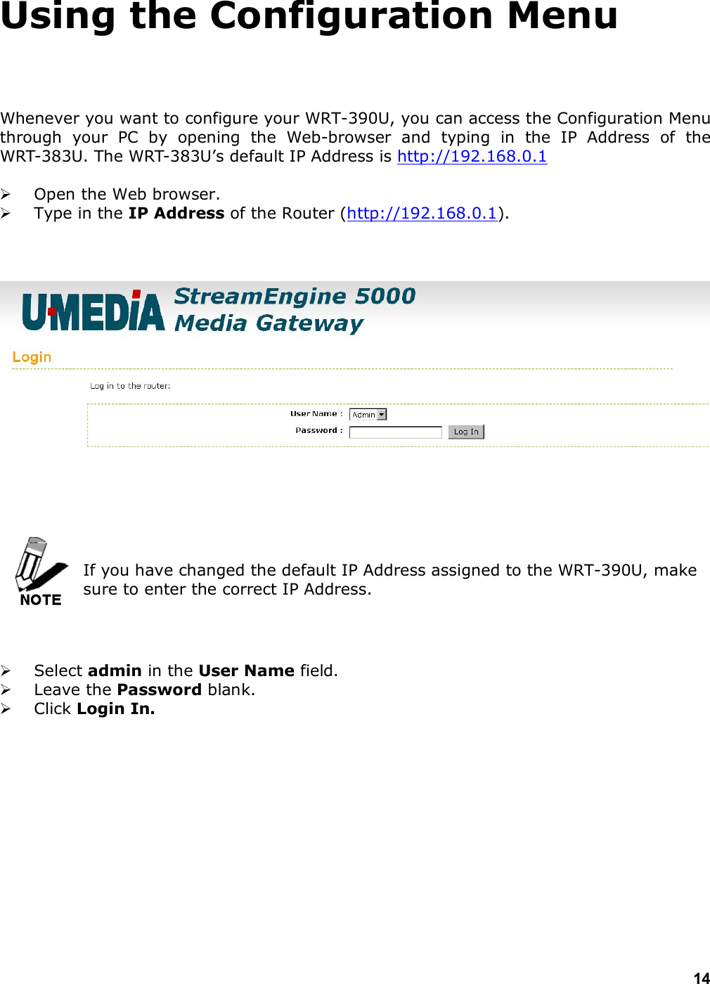
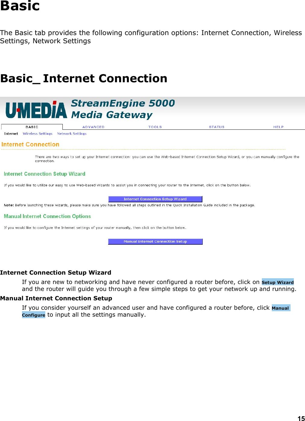
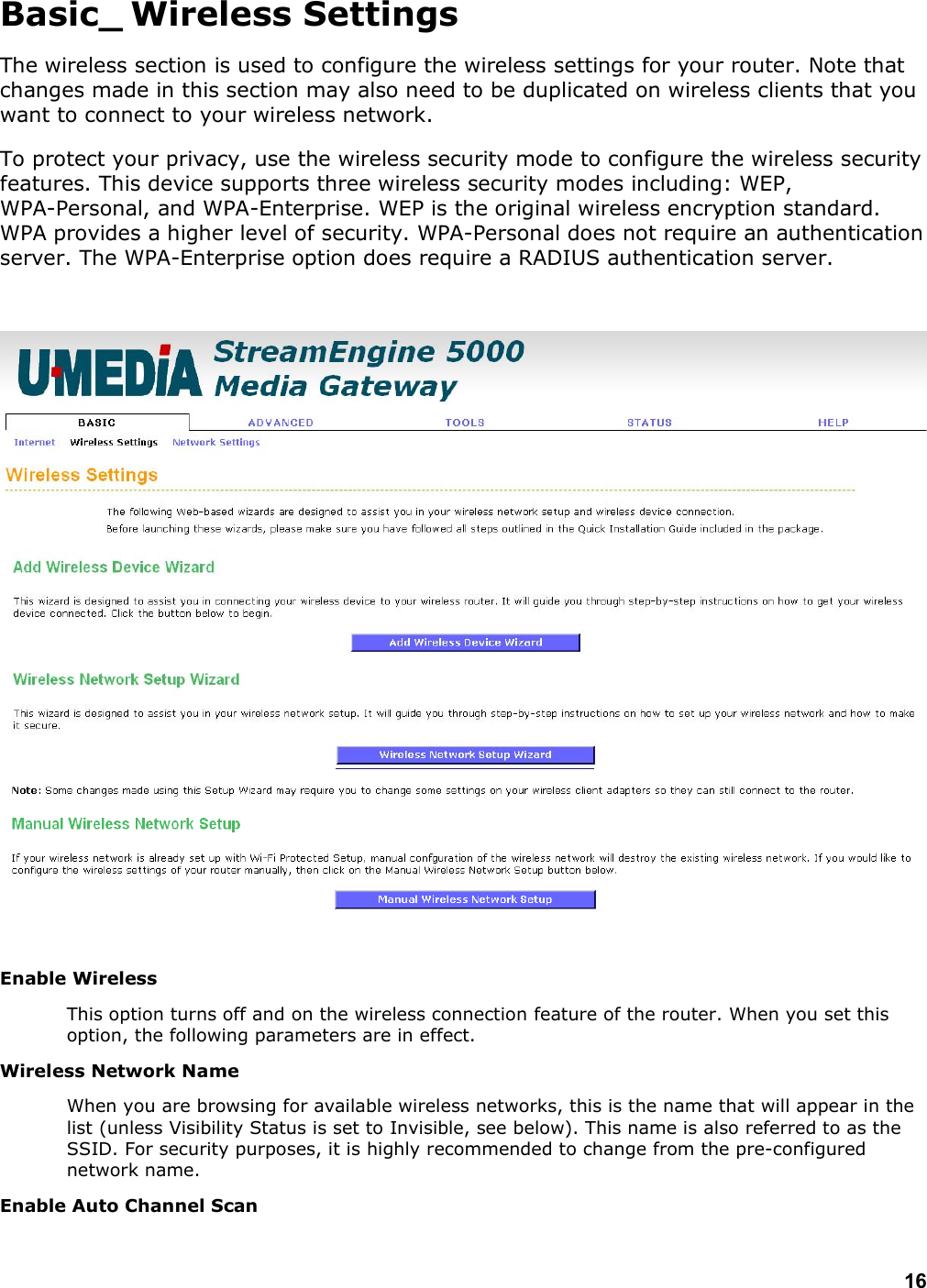
U MEDIA Communications WRT383U 2.4GHz 11n Draft 2.0 1+4 Port WLAN Router User Manual WRT 383U
U-MEDIA Communications, Inc. 2.4GHz 11n Draft 2.0 1+4 Port WLAN Router WRT 383U
UserManual.wiki
>
U MEDIA Communications
>
WRT383U User Manual
manual
Navigation menu
Upload a User Manual
Namespaces
Wiki Guide
HTML
PDF
Info
Views
User Manual
Discussion / Help
Navigation


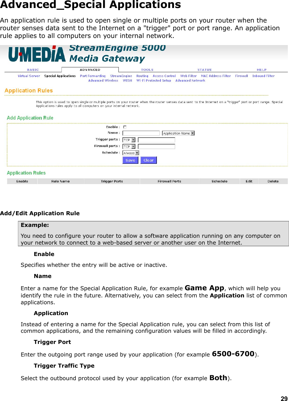
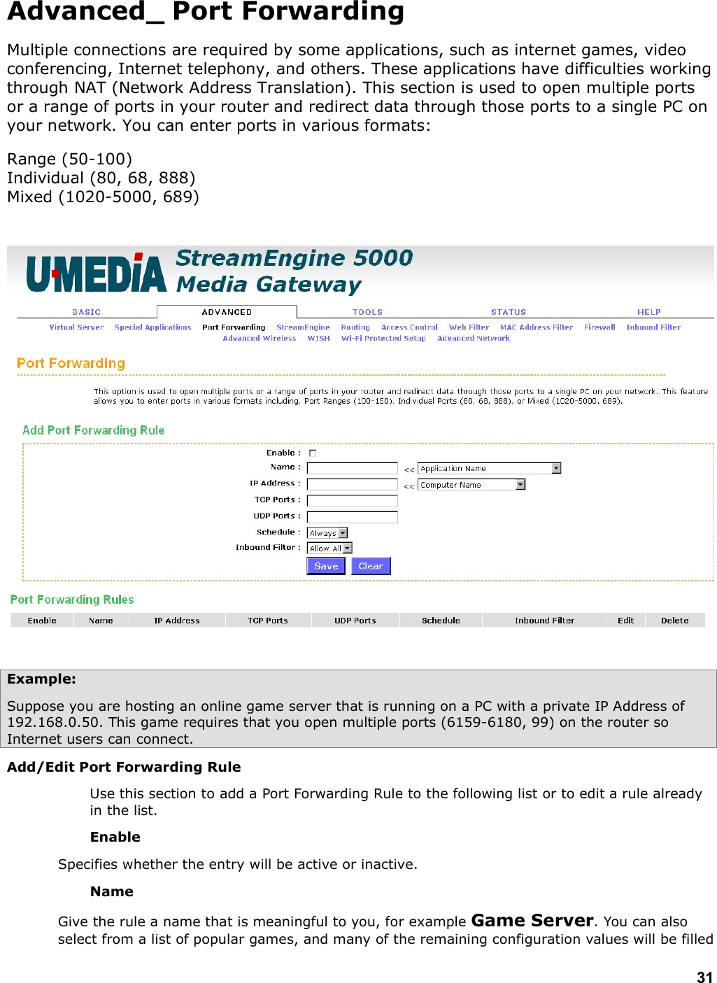
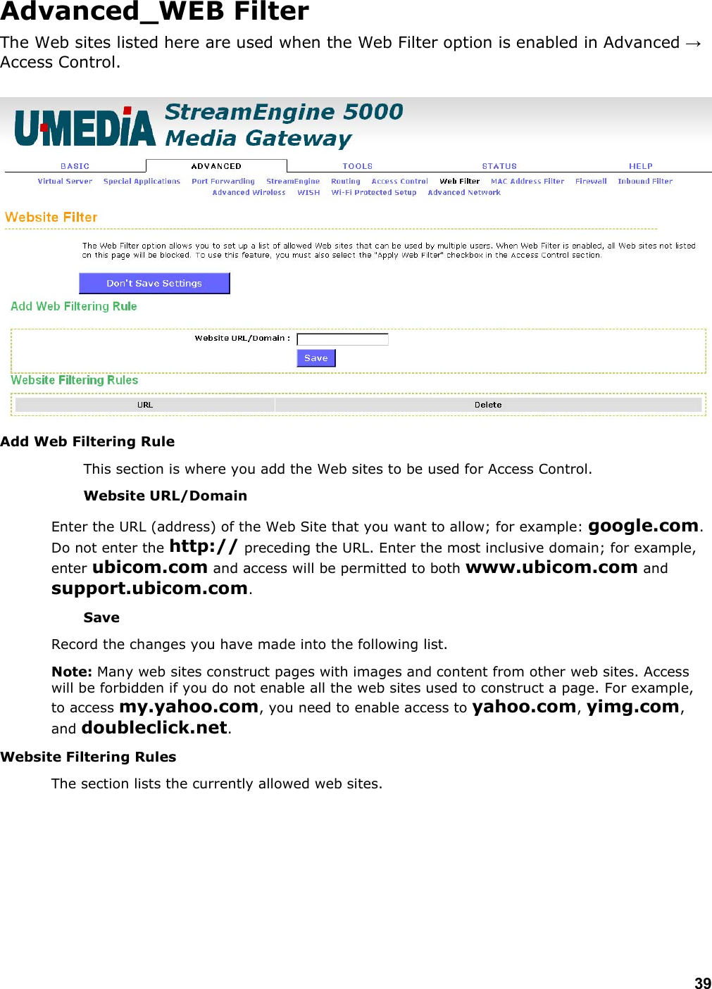
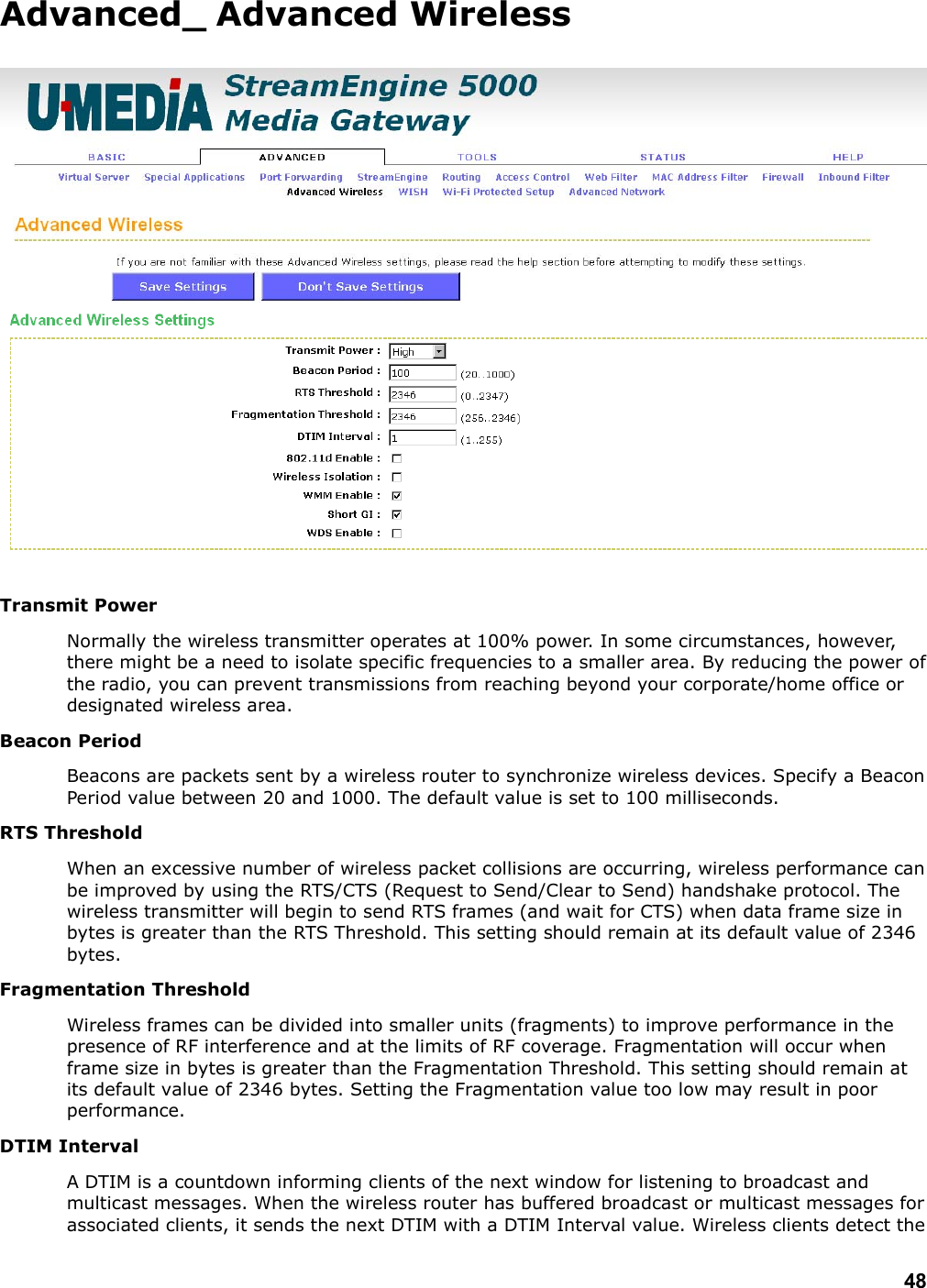
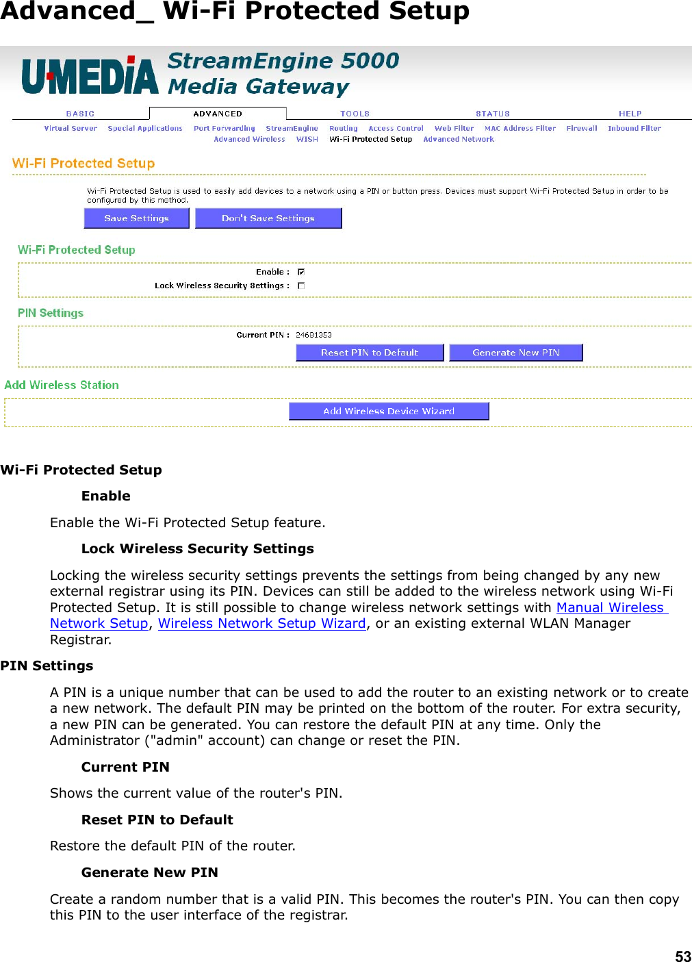
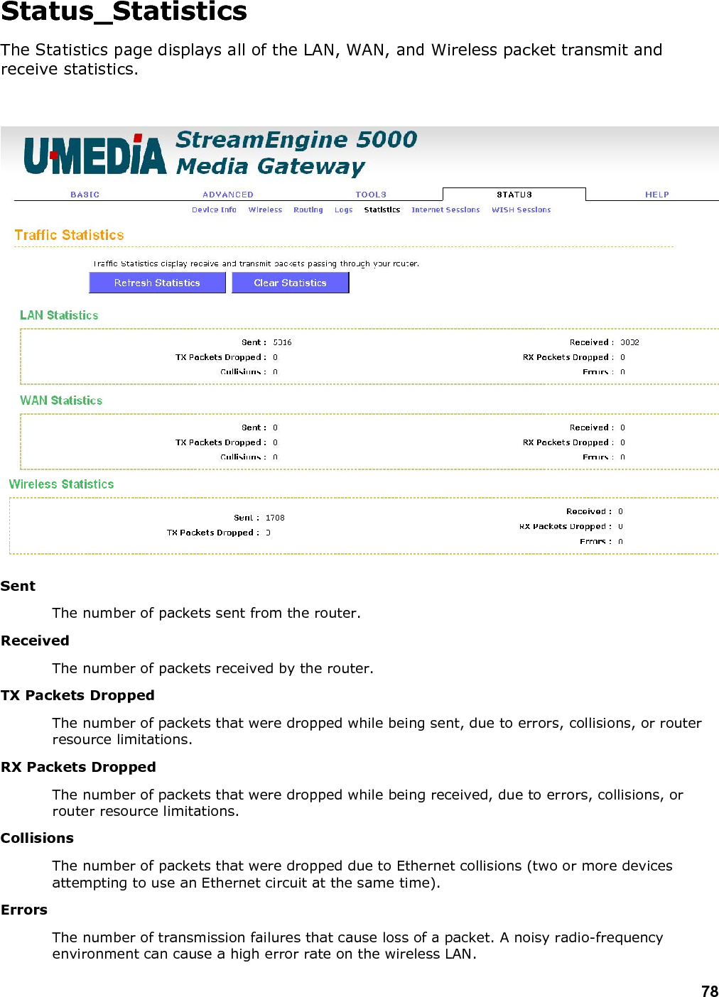
![26 Advanced The Advanced tab provides the following configuration options: Virtual Server, Port Forwarding, Application Rules, StreamEngine, Routing, Access Control, Website Filter, Network Filter, Firewall Settings, Inbound Filter, Advanced Wireless, WISH, Wi-Fi Protected Setup, Advanced Network, Advanced_Virtual Server The Virtual Server option gives Internet users access to services on your LAN. This feature is useful for hosting online services such as FTP, Web, or game servers. For each Virtual Server, you define a public port on your router for redirection to an internal LAN IP Address and LAN port. Example: You are hosting a Web Server on a PC that has LAN IP Address of 192.168.0.50 and your ISP is blocking Port 80. 1. Name the Virtual Server (for example: Web Server) 2. Enter the IP Address of the machine on your LAN (for example: 192.168.0.50 3. Enter the Private Port as [80] 4. Enter the Public Port as [8888] 5. Select the Protocol (for example TCP).](https://usermanual.wiki/U-MEDIA-Communications/WRT383U/User-Guide-823123-Page-27.png)