U MEDIA Communications WUB410 USB2.0 802.11a/b/g Wireless Network Adapter User Manual
U-MEDIA Communications, Inc. USB2.0 802.11a/b/g Wireless Network Adapter
Contents
- 1. User mnaual rev
- 2. User manual rev
User mnaual rev
1
802.11a/b/g Wireless USB Adapter
User's Guide
Version 1.0
2
Federal Communication Commission Interference Statement
This equipment has been tested and found to comply with the limits for a Class B digital device,
pursuant to Part 15 of the FCC Rules. These limits are designed to provide reasonable protection
against harmful interference in a residential installation. This equipment generates, uses and can
radiate radio frequency energy and, if not installed and used in accordance with the instructions,
may cause harmful interference to radio communications. However, there is no guarantee that
interference will not occur in a particular installation. If this equipment does cause harmful
interference to radio or television reception, which can be determined by turning the equipment off
and on, the user is encouraged to try to correct the interference by one of the following measures:
- Reorient or relocate the receiving antenna.
- Increase the separation between the equipment and receiver.
- Connect the equipment into an outlet on a circuit different from that
to which the receiver is connected.
- Consult the dealer or an experienced radio/TV technician for help.
FCC Caution: Any changes or modifications not expressly approved by the party responsible for
compliance could void the user's authority to operate this equipment.
For operation within 5.15 ~ 5.25GHz frequency range, it is restricted to indoor environment, and the
antenna of this device must be integral.
This device complies with Part 15 of the FCC Rules. Operation is subject to the following two
conditions: (1) This device may not cause harmful interference, and (2) this device must accept any
interference received, including interference that may cause undesired operation.
IMPORTANT NOTE:
FCC Radiation Exposure Statement:
This transmitter must not be co-located or operating in conjunction with any other antenna or
transmitter.
U-MEDIA declares imited in CH1~CH11 for 2.4 GHz
by specified firmware controlled in U.S.A.
WUB-410Z, ( FCC ID : SI5WUB410 ) listhat
Maximum average SAR (1g) is 0.793W/Kg.
3
CE Mark Warning
This is a Class B product. In a domestic environment, this product may cause radio interference, in
which case the user may be required to take adequate measures.
This transmitter must not be co-located or operation in conjunction with any other antenna or
transmitter.
4
Table of Contents
Federal Communications Commission (FCC) Interference statement 2
CE Mark Warning 3
Chapter 1 - Getting Started
1.1 About Your 802.11a/b/g WLAN USB Adapter 5
1.2 Package Content 5
1.3 System Requirement 5
1.4 LED Definition 6
1.5 Adapter Hardware and Utility Installation 6
1.6 Using the Utility to Configure Your Network 15
Chapter 2 – Maintenance
2.1 The Version Screen 26
2.2 Uninstalling the Driver 26
2.3 Uninstall the Client Utility 27
2.3 Upgrading the Wireless Utility 27
5
Chapter 1 - Getting Started
This chapter introduces the Adapter and prepares you to use the Wireless Utility.
1.1 About Your 802.11a/b/g WLAN USB Adapter
The Adapter is an IEEE 802.11a, 802.11b, and 802.11g compliant wireless LAN adapter. With the
Adapter, you can enjoy wireless mobility within almost any wireless networking environment.
The following lists the main features of your Adapter.
9 Your Adapter can communicate with other IEEE 802.11a/b/g compliant wireless devices.
9 Automatic rate selection.
9 Standard data transmission rates up to 54 Mbps.
9 Proprietary Atheros transmission rates of 108 Mbps
9 Offers 64-bit & 128-bit WEP (Wired Equivalent Privacy) data encryption for network
security.
9 Supports IEEE802.1x and WPA (Wi-Fi Protected Access).
9 Low CPU utilization allowing more computer system resources for other programs.
9 A built-in antenna.
9 Driver support for Windows XP/2000/ME/98SE
1.2 Package Content
¾ 802.11a/b/g WLAN USB Adapter
¾ Installation and Manual CD
¾ Quick Start Guide
¾ Warranty/Registration Adapter
1.3 System Requirement
z Pentium class notebook computers with at least one available USB slot
z Microsoft Windows XP or 2K
z CD-ROM drive
6
1.4 LED Definition
The following table describes the LED on the 802.11a/b/g WLAN USB Adapter
LED COLOR STATUS DESCRIPTION
OFF The Adapter has no connection
Blinking Slowly The Adapter is connected
LINK Blue
Blinking The Adapter is sending or receiving data
1.5 Adapter Hardware and Utility Installation
NOTE: If you have connected the USB Adapter to your computer, please
remove it first.
Follow the instructions below to install the USB Adapter and Utility.
STEP 1
Insert the Driver and Utility CD into CD drive
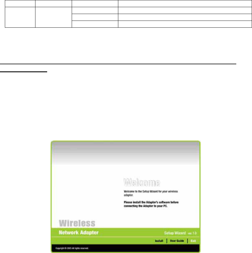
STEP 2
If your CD Autorun is enabled, the Main Installation Menu will show. (Otherwise open your CD
folder and double-click on the “setup.exe” file)
7
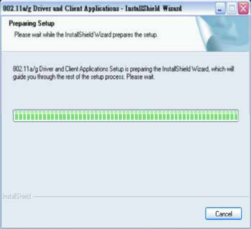
STEP 3
Click the button of INSTALL. The InstallShield wizard prepares for installation.
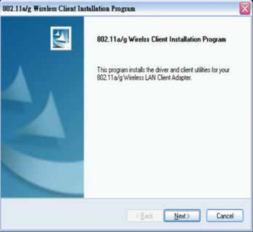
STEP 4
The InstallShield Wizard prompts you for confirmation. Click Next on the following menu.
8
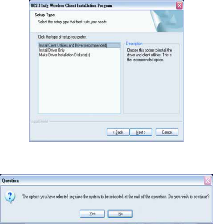
STEP 5
Choose to install client utility and driver or install driver only.
We recommend proceeding with “Install Client Utilities and Driver”
9
STEP 6
A warning question will pop up, click “Yes” on it.
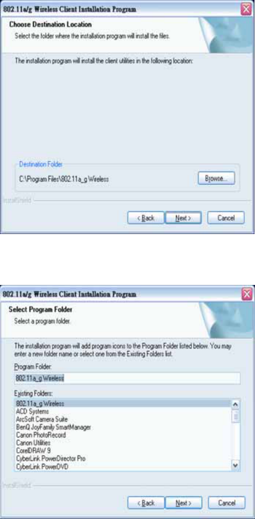
STEP 7
In the destination Folder screen you are asked to confirm the Destination Folder for the
application software. If you would like, you may change the destination folder to another location.
Click Next
10
STEP 8
Select a program folder and click on Next.
11
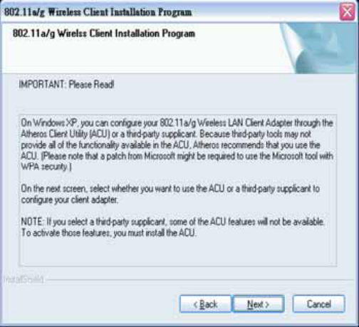
STEP 9
The installation gives you information regarding the Client Utility to be used. Click Next on it.
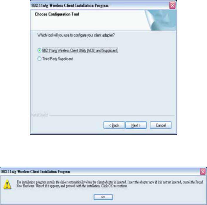
STEP 10
Choose the client utility. Click Next.
12
STEP 11
At this moment please insert your USB Adapter to your Laptop and click OK.
STEP 12
You will get the “Found News Hardware Wizard” menu; click on Cancel.
13
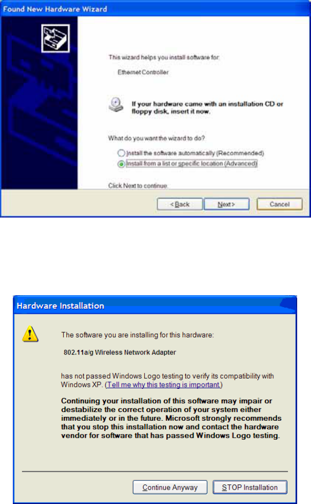
STEP 13
At the hardware installation menu click Continue Anyway.
(Our product has been tested under Windows XP and found to be fully compatible click
Continue Anyway.)
14
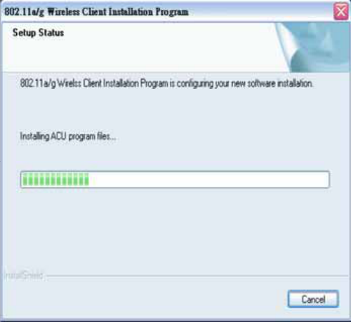
STEP 14
The setup configuration shows the installation progress
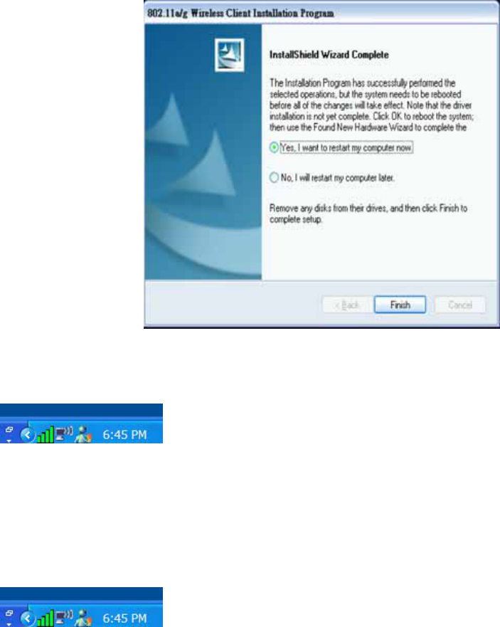
STEP 15
Click Finish to complete the client utility installation. Your computer will be rebooted.
15
STEP 16
After rebooting, The Client Utility icon resides on the Desktop at the System Tray automatically.
1.6 Using the Utility to Configure Your Network
The following are explanations on how to configure and use the Utility program. After completing
the installation procedure, a new icon as shown below will automatically appear in the lower right
tray bar.
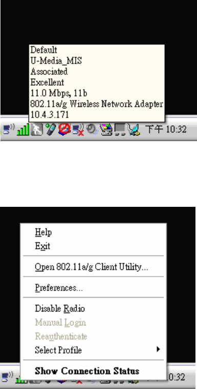
If you hold your mouse pointer over the icon, the profiles, quality, ip address display, along with the
name of the current configuration profile.
16
Press the right mouse button and click Open 802.11a/g Client Utility.
The 802.11a/g Client Utility window as shown below will appear.
17
The user can now use any of the management functions available in the 802.11a/g Client Utility.
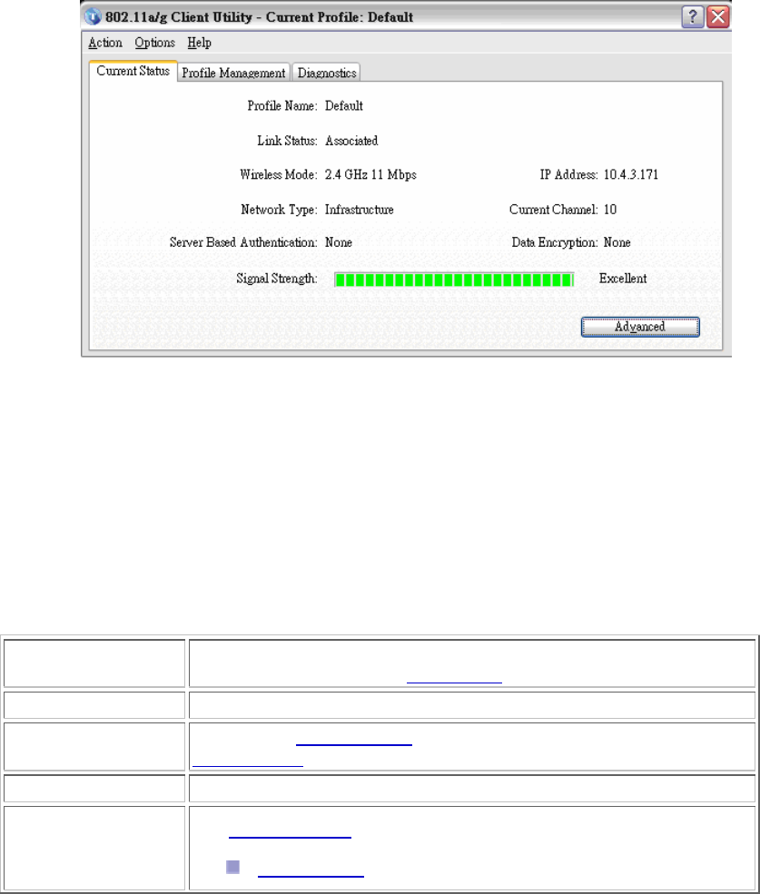
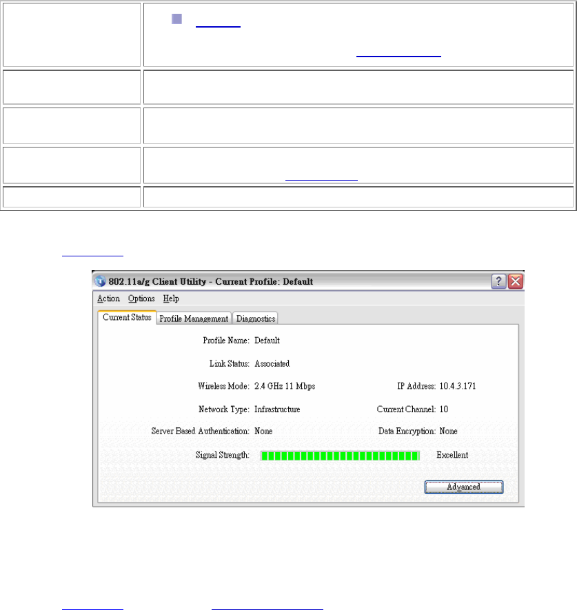
Current Status
The Current Status tab contains general information about the program and its operations. The
Current Status tab does not require any configuration.
The following table describes the items found on the Current Status screen.
Profile Name The name of the current selected configuration profile. Set up the
configuration name on the General tab.
Link Status Shows whether the station is associated to the wireless network.
Wireless Mode Displays the wireless mode. Configure the wireless mode on the
Advanced tab.
IP Address Displays the computer's IP address.
Network Type The type of network the station is connected to. The options include:
Infrastructure (access point)
18
Ad Hoc
Configure the network type on the Advanced tab.
Current Channel Shows the currently connected channel.
Server Based
Authentication Shows whether server based authentication is used.
Data Encryption Displays the encryption type the driver is using. Configure the
encryption type on the Security tab.
Signal Strength Shows the strength of the signal.
Click the Advanced button to see the advanced status diagnostics.
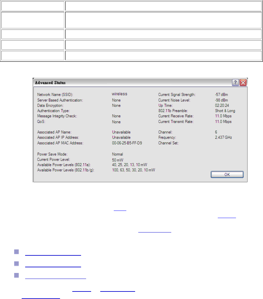
Advanced Status Information
Click the Advanced button on the Current Status tab of the Client Utility to see advanced
information about the program and its operations. The Current Status tab does not require any
configuration.
The following table describes the items found on the Advanced Status screen.

19
Network Name
(SSID) Displays the wireless network name.
Configure the network name on the General tab.
Server Based
Authentication Shows whether server based authentication is used.
Data Encryption Displays the encryption type the driver is using. Configure the
encryption type on the Security tab.
Authentication Type Displays the authentication mode.
Configure the authentication mode on the General tab.
Message Integrity
Check Shows whether MIC is enabled. MIC prevents bit-flip attacks on
encrypted packets.
Associated AP
Name Displays the name of the access point the wireless adapter is
associated to.
Associated AP IP
Address Shows the IP address of the access point the wireless adapter is
associated to.
Associated AP MAC
Address Displays the MAC address of the access point the wireless adapter is
associated to.
Power Save Mode Shows the power save mode. Power management is disabled in ad
hoc mode.
Configure the power save mode on the Advanced tab.
Current Power
Level Displays the transmit power level rate in mW.
Configure the transmit power level on the Advanced tab.
Available Power
Levels Shows the 802.11a and/or 802.11b/g available power levels.
Current Signal
Strength Shows the current signal strength in dBm.
Current Noise Level Displays the current noise level in dBm.
Up Time Shows how long the client adapter has been receiving power (in
hours:minutes:seconds). If the adapter runs for more than 24 hours,
the display shows in days:hours:minutes:seconds.
802.11b Preamble Displays the 802.11b preamble format.
Configure the preamble format on the Advanced tab.
Current Receive Shows the current receive rate in Mbps.
20
Rate
Current Transmit
Rate Displays the current transmit rate in Mbps.
Channel Shows the currently connected channel.
Frequency Displays frequency the station is using.
Channel Set Shows the current channel set.
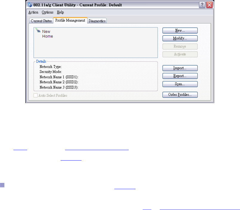
Create or Modify a Configuration Profile
To add a new configuration profile, click New on the Profile Management tab. To modify a
configuration profile, select the configuration from the Profile list and click the Modify button.
The Profile Management dialog box displays the General tab.
Profile Management:
Edit the General tab.
Edit the Security tab.
Edit the Advanced tab.
To configure a profile for ad hoc or access point (infrastructure) mode, edit the Network Type field
on the Advanced tab.
50.350mW for 11b, 31.989mW for 11g
16.218mW for 5.150 ~ 5.350GHz, 15.922mW for 5.725 ~ 5.850GHz

21
Note that the ACU only allows the creation of 16 configuration profiles. After the creation of 16
profiles, clicking the New button displays an error message. Remove an old profile or modify an
existing profile for a new use.
Auto Profile Selection Management
Including a profile in the auto selection feature allows the wireless adapter to automatically select
that profile from the list of profiles and use it to connect to the network.
Including a profile in auto profile selection:
1. On the Profile Management tab, click the Order Profiles button.
2. The Auto Profile Selection Management window appears, with a list of all created profiles
in the Available Profiles box.
3. Highlight the profiles to add to auto profile selection, then click Add. The profiles appear in
the Auto Selected Profiles box.
Ordering the auto selected profiles:
1. Highlight a profile in the Auto Selected Profiles box.
2. Click Move Up, Move Down, or Remove as appropriate.
The first profile in the Auto Selected Profiles box has highest priority, and the last profile
has lowest priority.
3. Click OK.
4. Check the Auto Select Profiles box.
5. Save the modified configuration file.
When auto profile selection is enabled by checking Auto Select Profiles on the Profile
Management tab, the client adapter scans for an available network. The profile with the
highest priority and the same SSID as one of the found networks is the one that is used to
connect to the network. If the connection fails, the client adapter tries the next highest
priority profile that matches the SSID, and so on.
With auto profile selection enabled, the wireless adapter scans for available networks. The highest
priority profile with the same SSID as a found network is used to connect to the network. On a
failed connection, the client adapter tries with the next highest priority profile.
22
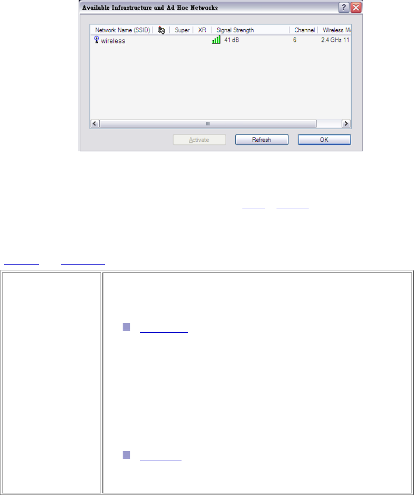
Scan Available Networks
Click the Scan button on the Profile Management tab to scan for available infrastructure and ad hoc
networks. On this list, click Refresh to refresh the list at any time.
Connecting to a different network
Highlight a network name and click the Activate button to connect an available network. If
no configuration profile exists for that network, the Profile Management window opens to
the General tab. Fill in the profile name and click OK to create the configuration profile for
that network.
23
Security Tab
In the Client Utility, access the Security tab by clicking New or Modify on the Profile Management
tab. Click the Security tab in the Profile Management window.
Edit the fields in the Security tab of Profile Management to configure the profile. To define the
security mode, select the radio button of the desired security mode. Make sure to also edit the
General and Advanced tabs.
WPA/WPA2 Enables the use of Wi-Fi Protected Access (WPA).
Choosing WPA/WPA2 opens the WPA/WPA2 EAP drop-down menu.
The options include:
EAP-FAST (Extensible Authentication Protocol-Flexible
Authentication via Secure Tunneling )
EAP-FAST is to support customers who cannot enforce a strong
password policy and wish to deploy an 802.1X EAP type that does not
require digital certificates, supports a variety of user and password
database types, supports password expiration and change, and is
flexible, easy to deploy, and easy to manage. For example, a customer
using Cisco LEAP who cannot enforce a strong password policy and
does not want to use certificates can migrate to EAP-FAST for protection
from dictionary attacks. (See help menu on configuration utility for more
details)
EAP-TLS (Extensible Authentication Protocol-Transport Layer
Security) is a Point-to-Point Protocol (PPP) extension supporting
additional authentication methods within PPP. Transport Layer
Security (TLS) provides for mutual authentication, integrity-protected

24
cipher suite negotiation, and key exchange between two endpoints.
EAP-TTLS (Extensible Authentication Protocol-Tunneled
Transport Layer Security) An EAP variant that provides mutual
authentication using a certificate for server authentication, and via a
secure TLS tunnel for the client
PEAP (EAP-GTC) (Protected Extensible Authentication
Protocol) authenticates wireless LAN clients using only server-side
digital certificates by creating an encrypted SSL/TLS tunnel between
the client and the authentication server. The tunnel then protects the
subsequent user authentication exchange.
PEAP (EAP-MSCHAP V2) (Protected Extensible
Authentication Protocol) To use PEAP (EAP-MSCHAP V2)
security, the server must have WPA-PEAP certificates, and
the server properties must already be set. Check with the IT
manager
LEAP (Lightweight and Efficient Application
Protocol) is the general framework for a set of
high-performance, efficient protocols which are ideal for
mobile and wireless applications. LEAP is designed to
address all the technical requirements of the wireless
data communications industry, and is oriented towards
providing the greatest benefit to the industry and the
consumer
WPA/WPA2
Passphrase Enables WPA/WPA2 Passphrase security.
Click on the Configure button and fill in the WPA/WPA2 Passphrase.
802.1x Enables 802.1x security. This option requires IT administration.
Choosing 802.1x opens the 802.1x EAP type drop-down menu. The
options include:
EAP-FAST
EAP-TLS
EAP-TTLS
PEAP (EAP-GTC)
PEAP (EAP-MSCHAP V2)

25
LEAP
If the access point that the wireless adapter is associating to has
WEP set to Optional and the client has WEP enabled, make sure that
Allow Association to Mixed Cells is checked on the Security Tab to
allow association.
26
Chapter 2 – Maintenance
This chapter describes how to uninstall or upgrade the Wireless Utility.
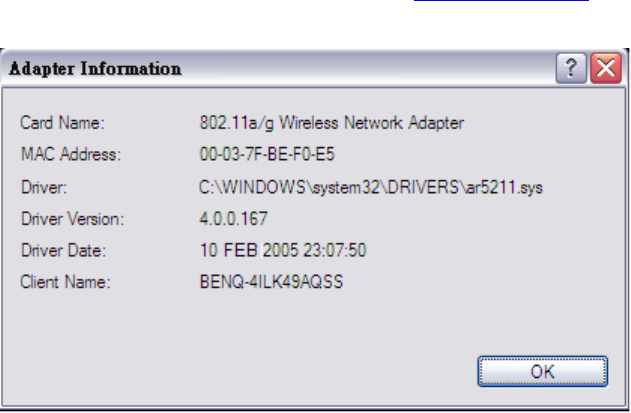
2.1 The Version Screen
In the Client Utility, check the adapter information by clicking Adapter Information button on the
Diagnostics tab.
2.2 Uninstall the Driver
Follow the steps below to remove (or uninstall) the USB Adapter driver from your computer.
Step 1. To remove the driver from the OS, go to Start -> Control Panel
Step 2. Double-click System
Step 3. Under Hardware tab, click Device Manager.
Step 4. Double-click Network Adapter
Step 5. Right-click mouse button on “802.11a/g Wireless Network Adapter”, and choose
Uninstall
Step 6. Click OK to confirm that you are going to uninstall the driver
27
2.3 Uninstall the Client Utility
Follow the steps below to remove the Client Utility from your computer.
Step 1. To remove the utility from the OS, go to Start -> Control Panel
Step 2. Double-click Add-Remove Programs
Step 3. Select 802.11a/g Wireless Client Installation Program, and click the Remove button
2.4 Upgrading the Wireless Utility
To perform the upgrade, follow the steps below.
Step 1. Download the latest version of the utility from the web site and save the file on your
computer.
Step 2. Follow the steps in Section 2.2 to remove the current Wireless Utility from your
computer.
Step 3. Restart your computer if prompted.
Step 4. After restarting, refer to the procedure in the Quick Start Guide to install the new utility.
Step 5. Check the version numbers in the Version screen to make sure the new utility is
installed properly.