U Pass CPR-303US RFID User Manual Appendix 11 Manual CPR 303US
U Pass Co., Ltd. RFID Appendix 11 Manual CPR 303US
UserManual.wiki
>
U Pass
>
CPR 303US User Manual
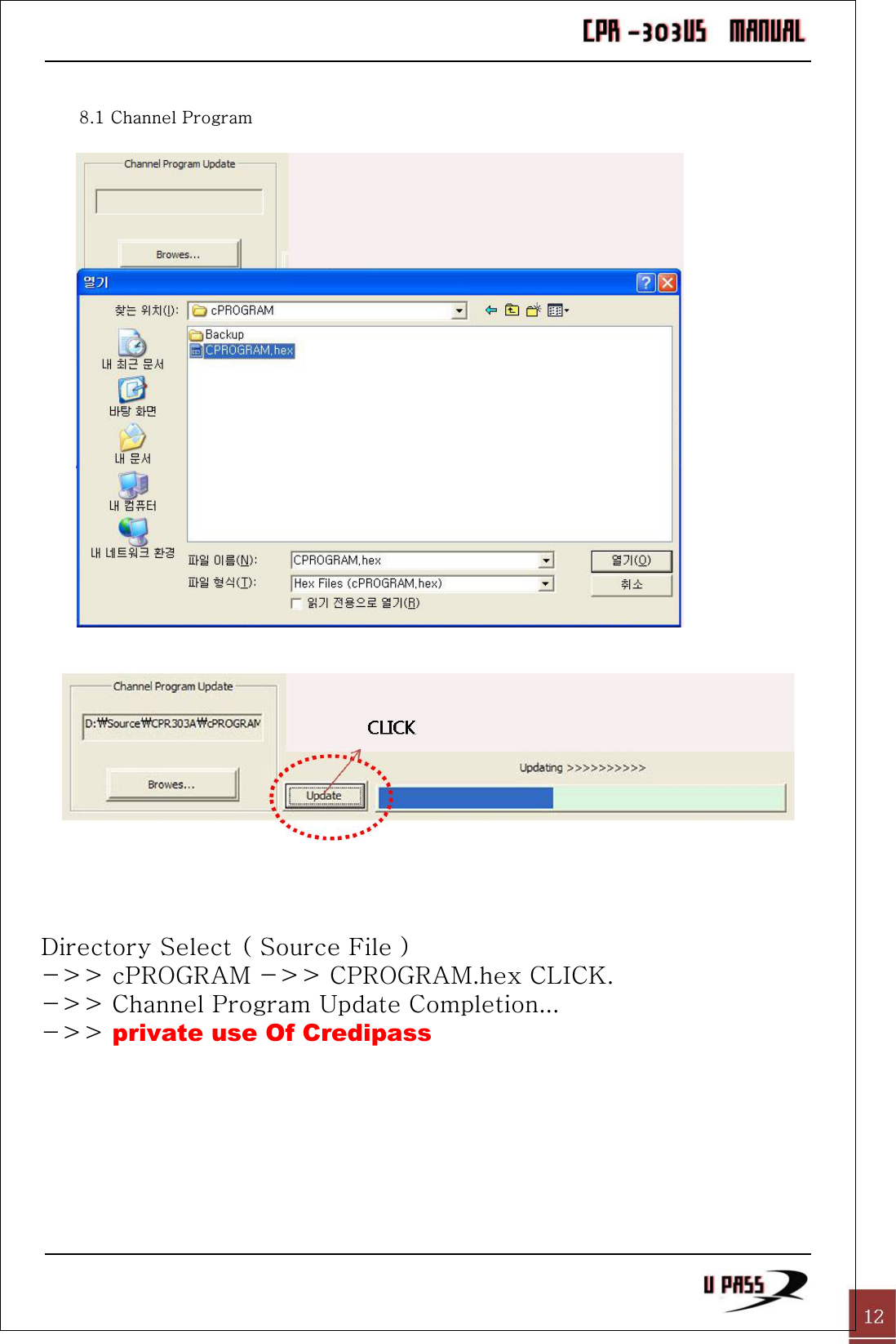
Users Manual
Navigation menu
Upload a User Manual
Namespaces
Wiki Guide
HTML
PDF
Info
Views
User Manual
Discussion / Help
Navigation
![4.3 PIN ASSIGN4.3.1. Power ( DC 24V ) UHF READER [ RED ] [ BLACK ] ->( Connection without Polarity )4.3.2. RS-232 [ GREEN ] [ WHITE ] [ GRAY ] -> Connection without Polarity because NO VOLTAGE BIAS. 4.3.3 RELAY [ ORANGE ] [ VIOLET ] Black RedEx) Power Supply DC 24V 1A](https://usermanual.wiki/U-Pass/CPR-303US/User-Guide-1179911-Page-13.png)
![4.3.4 Loop Detector [ BROWN ] [ GRAY ] Gray Brown Loop DetectorChapter 5. Contact U Pass Office & Technic Support - No.509 Daeryung Post TowerIII, 182-4, Guro-3Dong, Guro-Gu 152-847 Korea. TEL:+82-2-488-8807 FAX:+82-2-488-8277](https://usermanual.wiki/U-Pass/CPR-303US/User-Guide-1179911-Page-14.png)