U S Department Of Defense Sets Electron Tube Tv 2 Users Manual Vdx9155.tmp
2015-02-03
: U-S-Department-Of-Defense U-S-Department-Of-Defense--Sets-Electron-Tube-Tv-2-U-Users-Manual-478480 u-s-department-of-defense--sets-electron-tube-tv-2-u-users-manual-478480 u-s-department-of-defense pdf
Open the PDF directly: View PDF ![]() .
.
Page Count: 82
- TABLE OF CONTENTS
- WARNING
- CHAPTER 1
- CHAPTER 2
- CHAPTER 3
- CHAPTER 4
- CHAPTER 5
- APPENDIX I
- APPENDIX II
- APPENDIX III
- PARAGRAPHS
- PARA 1
- PARA 2
- PARA 3
- PARA 4
- PARA 5
- PARA 6
- PARA 7
- PARA 8
- PARA 9
- PARA 10
- PARA 11
- PARA 12
- PARA 13
- PARA 14
- PARA 15
- PARA 16
- PARA 17
- PARA 18
- PARA 19
- PARA 20
- PARA 21
- PARA 22
- PARA 23
- PARA 24
- PARA 25
- PARA 26
- PARA 27
- PARA 28
- PARA 29
- PARA 30
- PARA 31
- PARA 32
- PARA 33
- PARA 34
- PARA 35
- PARA 36
- PARA 37
- PARA 38
- PARA 39
- PARA 40
- PARA 41
- PARA 42
- PARA 43
- PARA 44
- PARA 45
- PARA 46
- PARA 47
- PARA 48
- PARA 49
- FIGURES
- PAGES
WARNING
DANGEROUS VOLTAGES EXIST IN THIS EQUIPMENT
Be careful when working on the 290-volt plate and screen supply
circuits, or on the 115-volt ac line connections.
DON’T TAKE CHANCES!

Changes now in force: C 2 and C 3
TM 11-6625-316-12
C3
CHANGE
HEADQUARTERS
DEPARTMENT OF THE ARMY
No. 3
WASHINGTON, D. C., 10 July 1974
Operator and Organizational Maintenance Manual
TEST SETS, ELECTRON TUBE
TV-2/U, TV-2A/U, TV-2B/U, AND TV-2C/U
TM 11-6625-316-12, 16 March 1961, is changed as follows:
Page 5, paragraph 1.1. Delete and substitute:
1.1 Indexes of Publications
a. DA Pam 310-4. Refer to the latest issue of DA Pam 310-4
to determine whether there are new editions, changes, or addi-
tional publications pertaining to the equipment.
b. DA Pam 310.7. Refer to DA Pam 310-7 to determine whether
there are modification work orders (MWO’S) pertaining to the
equipment.
Paragraph 2. Delete and substitute the following:
2. Forms and Records
a. Reports of Maintenance and Unsatisfactory Equipment,
Maintenance forms, records, and reports which are to be used by
maintenance personnel at all maintenance levels are listed in and
prescribed by TM 38-750.
b. Report of Packaging and Handing Deficiencies. Fill out and
forward DD Form 6 (Report of Packaging and Handling De-
ficiencies) as prescribed in AR 700-58/NAVSUP PUB 378/AFR
71-4/MCO P4030.29, and DSAR 4145.8.
c. Discrepancy in Shipment Report (DISREP) (SF 361). Fill
out and forward Discrepancy in Shipment Report (DISREP)
(SF 361) as prescribed in AR 55-38/NAVSUPINST 4610.33/
AFM 75-18/MCO P4610.19A, and DSAR 4500.15.
2.1 Reporting of Errors
The reporting of errors, omissions, and recommendations for im-
proving this Duplication by the individual user is encouraged.
1
Reports should be submitted on DA Form 2028 (Recommended
Changes to Publications and Blank Forms) and forwarded direct
to Commander, US Army Electronics Command, ATTN: AMSEL-
MA-C, Fort Monmouth, NJ 07703.
Page 7, paragraph 5. Delete and substitute:
5. Item Comprising an Operable Equipment
Test Sets, Electron Tube TV-2/U, TV-2A/U, TV-2B/U, and
TV-2C/U (6625-669-0263) each comprises an operable equip-
ment,
Page 11, paragraph 9c. Delete the second sentence.
Page 61, appendix III. Delete appendix III in it’s
eluding final foldout, entitled: Items Comprising
Equipment).
By Order of the Secretary of the
Official:
VERNE L. BOWERS
Major General, United States
The Adjutant General
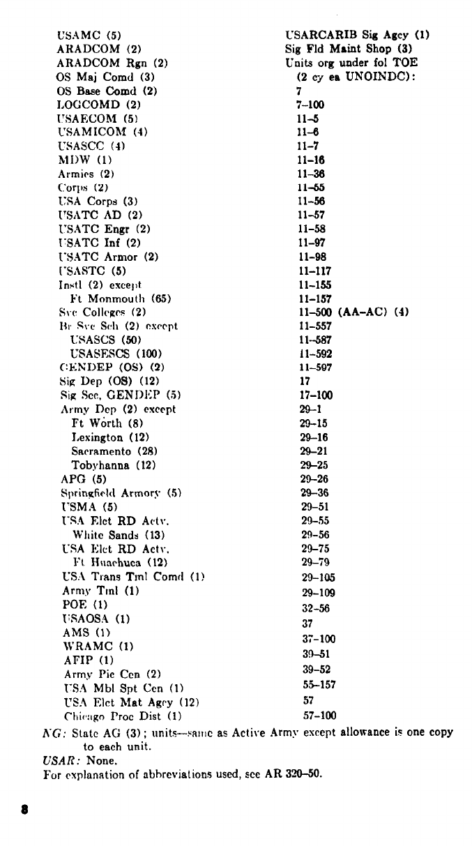
Distribution:
Active Army:
USASA (2)
CNGB (1)
ACSC-E (2)
Dir of Trans (1)
COE (1)
TSG (1)
USAARENBD (1)
USAMB (10)
AMC (1)
MICOM (2)
TECOM (2)
TRADOC (2)
ARADCOM (2)
ARADCOM Rgn (2)
OS Maj Cored (4)
LOGCOMD (3)
USACC (4)
MDW (1)
Armies (2)
Army:
entirety (in-
an Operable
CREIGHTON W. ABRAMS
General, United States Army
Chief of Staff
Army
Corps (2)
HISA (Ft Monmouth) (18)
Ft Gordon (10)
Ft Huachuca (10)
Ft Carson (5)
Ft Richardson (ECOM Oft) (2)
WSMR (1)
Svc Colleges (1)
USASESS (15)
USAINTCS (3)
USAADS (2)
USAFAS (2)
USAARMS (2)
USAIS (2)
USAES (2)
AD (1) except
SAAD (30)
LBAD (14)
TOAD (14)
2
ATAD (10)
USA Dep (2)
Sig Sec USA Dep (2)
Sig Dep (2)
MAAG (1)
USARMIS (1)
ATS (1)
WRAMC (1)
USAERDAA (1)
USAERDAW (1)
Sig FLDMS (1)
Units org under fol TOE: 1 ea.
7
7-100
11-16
11-36
11-97
11-98
11-117
11-302
11-500 (AA-AC)
ARNG: State AG (3).
17
29-1
29-15
29-16
29-21
29-26
29-26
29-36
29-55
29-56
29-105
29-109
29-134
29-186
32-56
37
39-51
55-157
57
57-100
USAR: None
For explanation of abbreviations used, see AR 310-50.

TECHNICAL MANUAL
No. 11-6625-316-12
TECHNICAL ORDER
* TM 11-6625-316-12
DEPARTMENTS OF THE ARMY
AND THE AIR FORCE
WASHINGTON 25, D. C., 16 March 1961
TEST SETS, ELECTRON TUBE TV-2/U, TV-2A/U,
CHAPTER 1.
Section I.
II.
CHAPTER 2.
Section I.
II.
III.
IV.
AND TV-2 B/U
Paragraph
INTRODUCTION
Genera’
Scope _ _ _ _ _ _ _ _ _ _ _ _ _ _ _ _ _ _ _ _ _
Forms and records _ _ _ _ _ _ _ _ _ _ _ _ _ _ _ _ _ _ _
Description and data
Purpose and use _ _ _ _ _ _ _ _ _ _ _ _ _ _ _
Technical characteristics _ _ _ _ _ _ _ _ _ _ _ _ _ _ _ _ _ _
Components of Test Set, Electron Tube
TV-2(*)/U.
Description of Test Set, Electron Tube
TV-2(*)/U.
Differences in models _ _ _ _ _ _ _ _ _ _
OPERATION
Service upon receipt of equipment
Unpacking _ _ _ _ _ _ _ _ _ _ _ _ _ _ _ _ _ _
Checking unpacked equipment _ _ _ _ _ _ _ _ _ _ _ _
Operator’s controls and indicators _ _ _ _ _ _ _ _ _
Damage from improper settings _ _ _ _ _ _ _ _ _
Operating controls and indicators _ _ _ _ _ _ _
Tube test data _ _ _ _ _ _ _ _ _ _ _ _ _ _ _ _ _ _ _ _ _ _
Preliminary operating procedures
Operating precautions _ _ _ _ _ _ _ _ _ _ _ _ _ _ _ _ _
Tube test sockets and test adapters _ _ _ _ _ _ _ _ _ _ _ _
Preliminary starting procedure _ _ _ _ _ _ _ _ _ _ _
Operation under usual conditions
Starting procedures _ _ _ _ _ _ _ _ _ _ _ _ _ _ _ _ _ _
Zero adjustment of PERCENT QUALITY
meter.
1
2
3
4
5
6
7
8
9
10
11
12
13
14
15
16
17
Page
5
5
6
6
7
8
8
10
10
12
12
16
19
19
20
22
23
This manual supersedes so much of TM 11-2661, 11 May 1955, including
C4, 8 November 1957; C5, 21 April 1958; C6, 15 May 1959, as pertains to
operator’s and organizational maintenance and so much of TM 11-6625-316-
12P, 23 July 1959, as pertains to the basic issue items list and the maintenance
allocation chart.
1
Section IV.
CHAPTER 3.
4.
5.
Section I.
II.
APPENDIX I.
II.
III.
Short test _ _ _ _ _ _ _ _ _ _ _ _ _ _ _ _ _ _ _ _ _ _ _ _ _ _ _ _ _ _ _ _ _ _ _
Interelement leakage test _ _ _ _ _ _ _ _ _ _ _ _ _
Filament continuity test _ _ _ _ _ _ _ _ _ _ _ _ _ _ _ _ _ _
Transconductance test _ _ _ _ _ _ _ _ _ _ _ _ _ _ _ _ _ _ _ _ _ _ _ _
Gas test _ _ _ _ _ _ _ _ _ _ _ _ _ _ _ _ _ _ _ _ _ _ _ _ _ _ _ _ _ _ _ _ _ _ _ _ _
Emission test _ _ _ _ _ _ _ _ _ _ _ _ _ _ _ _ _ _ _ _ _ _ _ _ _ _ _ _ _ _ _ _
Voltage regulator and gas rectifier test _ _ _ _ _ _
Procedure for reading plate current (less than
50 milliamperes) of triode tubes.
Thyratron test _ _ _ _ _ _ _ _ _ _ _ _ _ _ _ _ _
Electron-ray indicator test _ _ _ _ _ _ _ _ _ _ _ _ _ _ _
Ballast tube test _ _ _ _ _ _ _ _ _ _ _ _ _ _ _
Indicator lamp test _ _ _ _ _ _ _ _ _ _ _ _ _ _ _ _ _ _ _ _ _ _ _ _ _ _ _
Complete tube test _ _ _ _ _ _ _ _ _ _ _ _ _ _ _ _ _ _ _
Stopping procedure _ _ _ _ _ _ _ _ _ _ _ _ _ _
PERATOR’S MAINTENANCE
General _ _ _ _ _ _ _ _ _ _ _ _ _ _ _ _ _ _ _ _ _ _ _ _ _ _ _ _ _ _ _
Preventive maintenance_ _ _ _ _ _ _ _ _ _ _ _ _ _ _ _ _ _
Visual inspection _ _ _ _ _ _ _ _ _ _ _ _ _ _ _ _ _ _ _ _ _ _ _ _ _ _ _ _
Operational checklist _ _ _ _ _ _ _ _ _ _ _ _ _
Removal and replacement of chassis _ _ _ _ _ _ _ _ _ _ _ _
Tube replacement _ _ _ _ _ _ _ _ _ _ _ _ _ _ _ _ _ _ _ _ _ _ _
Preferred-type tubes _ _ _ _ _ _ _ _ _ _ _ _ _ _ _ _ _ _ _ _ _
Replacement of fuses and lamps _ _ _ _ _ _ _ _ _ _ _ _
ORGANIZATIONAL MAINTENANCE
General _ _ _ _ _ _ _ _ _ _ _ _ _ _ _ _ _ _ _ _ _ _ _ _
Tools and materials require _ _ _ _ _ _ _ _ _ _ _ _ _ _
Preventive maintenance _ _ _ _ _ _ _ _ _ _ _ _
Visual inspection _ _ _ _ _ _ _ _ _ _ _ _ _ _ _ _ _ _
Equipment performance checklist _ _ _ _ _ _ _ _ _ _ _ _ _
Replacement of test adapters _ _ _ _ _ _ _ _ _ _ _ _ _ _ _
SHIPMENT, LIMITED STORAGE, AND
DEMOLITION TO PREVENT ENEMY
USE.
Shipment and limited storage
Disassembly of equipment _ _ _ _ _ _ _ _ _ _ _ _ _ _ _ _ _
Repackaging for shipment or limited storage
Demolition of materiel to prevent enemy use
Authority for demolition
Methods of destruction _ _ _ _ _ _ _ _ _
REFERENCES_ _ _ _ _ _ _ _ _ _ _ _ _ _ _ _ _
MAINTENANCE ALLOCATION _ _ _ _ _ _ _ _ _ _ _ _ _
BASIC ISSUE ITEMS LIST _ _ _ _ _ _ _ _ _ _ _ _ _ _ _ _ _
18
19
20
21
22
23
24
25
26
27
28
29
30
31
32
33
34
35
36
37
38
39
40
41
42
43
44
45
46
47
48
49
--
--
--
23
24
25
25
26
27
28
29
30
31
32
32
33
37
38
38
41
41
44
45
45
46
47
47
47
48
48
54
55
55
57
57
58
59
64
2


CHAPTER 1
INTRODUCTION
Section I. GENERAL
1. Scope
a. This manual describes Test Sets, Electron Tube TV-2/U,
TV–2A/U, and TV–2B/U (fig. 1) and covers operation and the
operator’s and organizational maintenance. It includes instruc-
tions for operation under usual conditions, for cleaning and in-
spection of the equipment, and for replacement of parts available
to first and second echelon maintenance.
b. Official nomenclature followed by (*) is used to indicate all
models of the equipment item covered in this manual. Thus Test
Set, Electron Tube TV–2 (*)/U represents Test Sets, Electron
Tube TV-2/U, TV–2A/U, and TV-2B/U.
c. Throughout this manual, Test Set, Electron Tube TV–2 ( * ) /U
is referred to as the tube tester.
2. Forms and Records
a. Unsatisfactory Equipment Report. Fill out and forward DD
Form 787–1 (Electronic Failure Report, Signal Equipment) to the
Commanding Officer, U.S. Army Signal Materiel Support Agency,
ATTN: SIGMS–ML, Fort Monmouth, N. J., as prescribed in AR
700-39.
b. Report of Damaged or Improper Shipment. Fill out and for-
ward DD Form 6 (Report of Damaged or Improper Shipment)
as prescribed in AR 700–58.
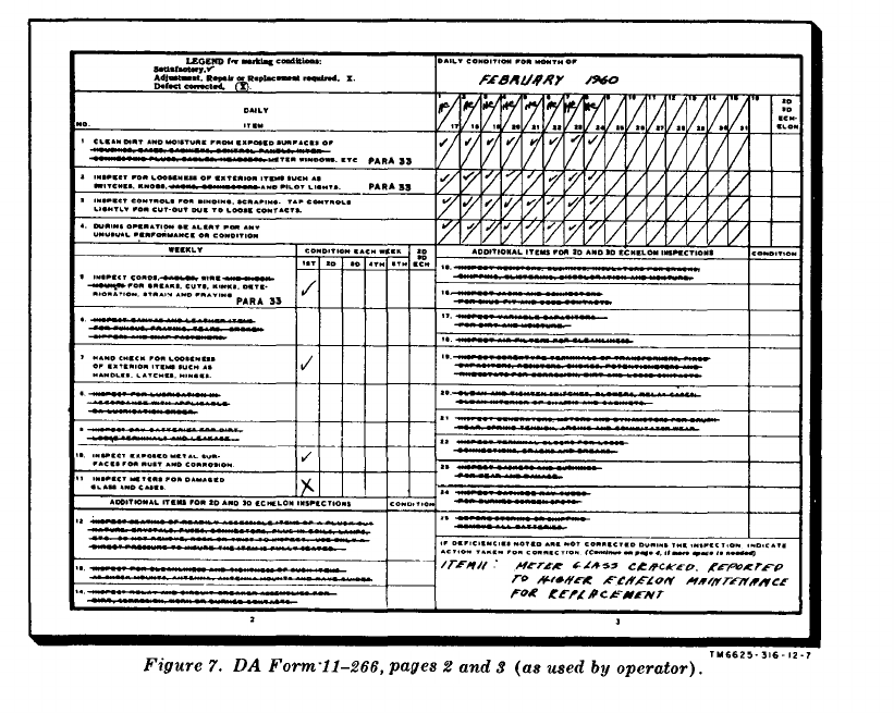
c. Preventive Maintenance Forms. Prepare DA Form 11–266
(figs. 6, 7, and 9) (Maintenance Check List for Signal Equipment
(Test Equipment) ) in accordance with instructions on the form.
d. Parts List Form. Forward DA Form 2028 (Recommended
Changes to DA Technical Manual Parts Lists or Supply Manuals
7, 8, or 9), directly to the Commanding Officer, U.S. Army Signal
Materiel Support Agency, ATTN: SIGMS-ML Fort Monmouth,
N. J., with comments on parts listings.
e. Comments on Manual. Forward all other comments on this
publication directly to the Commanding Officer, U.S. Army Signal
5
Materiel Support Agency, ATTN: SIGMS-PA2d, Fort Monmouth,
N.J.
Section II. DESCRIPTION AND DATA
3. Purpose and Use
Test Set, Electron Tube TV–2(*)/U (fig. 1) is a portable tube
tester of the dynamic mutual conductance type. It is used to test
and to measure performance capabilities and to determine rejec-
tion limit for electron tubes used in receivers, low-powered trans-
mitters, and other electronic equipment. The following tests can
be made with the tube tester.
a. Short test.
b. Interelement leakage test.
c. Filament continuity test.
d. Dynamic mutual conductance test for amplifier tubes.
e. Gas test for amplifier tubes.
f. Emission test for vacuum rectifier tubes.
g. Test of gas rectifier tubes.
h. Test of voltage regulator tubes.
i. Plate current tests for triodes.
j. Test of thyratron tubes.
k. Electron-ray indicator test for electronic indicator tubes.
l. Ballast tube test.
4. Technical Characteristics
a. Power supply:
Input voltage ________________ 103.5 to 126.5 volts ac.
Frequency------------------------ 50 to 1,000 cps, single-phase.
Power consumption -------------70 watts (no tube under test).
Temperature range ----------- Satisfactory operation from -4° F. to 125° F.
b. Meters:
FILAMENT VOLTS meter:
Type------------------------------ Dc voltmeter movement.
Frequency range ----------- 50 to 1,000 cps.
Ac voltage ranges -------------- 0 to 2.5 volts, 0 to 10 volts, 0 to 40 volts, and
0 to 120 volts. Redlines at 0.625, 6.3, 12.6,
and 117 on appropriate scale.
Accuracy -------------------------- ±5 percent error at full scale.
GRID BIAS VOLTS meter:
Type ---------------------------------Dc voltmeter.
Sensitivity ---------------- 1,000 ohms per volt.
Dc voltage ranges ---------- 0 to 5 volts, 0 to 10 volts, and 0 to 50 volts.
Accuracy-------------------------- ±2 percent error at full scale.
6
TM 11-6625-816-12
PLATE
meter:
Type _ _ _ _ _ _ _ _ _ _ _ _ _ _ _ _ _ _ _ _ _ DC voltmeter.
Sensitivity ----------------- 1,000 ohms per volt.
Voltage ranges. ---------------0 to 250 volts dc, with redlines at 45, 90, 180,
and 225.
0 to 50 volts ac, with 20 AC and 35 AC marked
in red.
Ohmmeter ranges
------------0.1 to 1.0 megohms.
Accuracy--------------
±2 percent error at full scale.
SCREEN VOLTS meter:
Type -----------------------Dc voltmeter.
Sensitivity -----------------1,000 ohms per volt.
Voltage range ------------- 0 to 250 volts dc.
Accuracy-------------±2 percent error at full scale.
SIGNAL meter:
Type--------------------- Ac iron vane-type ammeter.
Frequency range--------.50 to 1,000 cps.
Meter range
------------45 ma ac full scale; redline at approximately
two-thirds full scale (35 ma ac).
Accuracy----------------
±5 percent error at full scale.
PERCENT QUALITY meter (transconductance):
Type------------------------ Dc microammeter.
Sensitivity-------------------10,000 ohms per volt (150 microamperes full-
scale deflection).
Percent quality ranges ------------ To 60,000 micromhos (in equivalent percentage
values).
Accuracy __________________ ±2 percent error at full scale.
c. Number of electron tubes -------------------------- 3
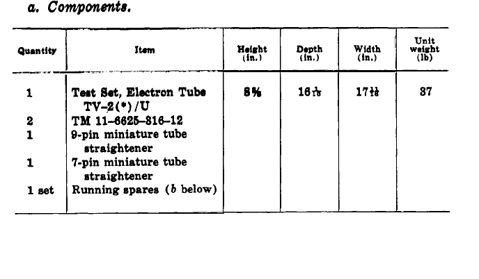
5. Components of Test Set, Electron Tube TV-2(*)/U
7
b. Running Spares.
QuantityItem Ref symbol
1
Electron tube, 83------------------------------ V1
1
Electron tube,6X4W----------------------------- V2, V3
5Fuses,3 ampere, 250 volts, ¼ x 1¼ F1, F2
inches.
1
Glow lamp, NE-51 _ _ _ _ _ _ _ _ _ _ _ _ _ _ _ _ _ _ _ _ 11C, 12C
Note. Running spares listed above are stored in designated positions on the inside cover and
chassis (figs. 1 and 8 ) of the tube tester.
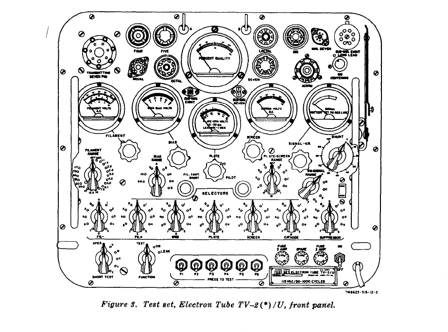
6. Description of Test Set, Electron Tube TV-2(*)/U
(fig. 1)
a. Test Set, Electron Tube TV-2(*)/U (tube tester) is housed
in a carrying case equipped with a carrying handle, two electrical
clips for connection to the top cap of a tube under test, operating
and spare tubes, fuses, indicating lamps, and miniature tube pin
straighteners. The cover is secured to the case by luggage-type
fasteners. Power cord brackets and a dummy power cord recep-
tacle on the panel are used to secure and store the power cable.
Tube test data is given on a roll chart; the roll chart case is
mounted inside the cover of the tube tester. A condensed summary
of operating instructions also is mounted inside the cover of the
tube tester. The cover is hinged by slip hinges and can be removed
from the case. Two handles attached to the panel permit easy
lifting of the tube tester from the case.
b. All indicating meters, switches, controls, and tube test sockets
are located on the panel of the equipment. The necessary data for
setting and operating the controls to test the various tube types
are contained in the tube test data roll chart (a above). Two
electrical clips (A and B, fig. 3) provide connection to external
caps of tubes as reqired. One end of the power cord is perma-
nently attached to the panel; the other end terminates in a male
plug.
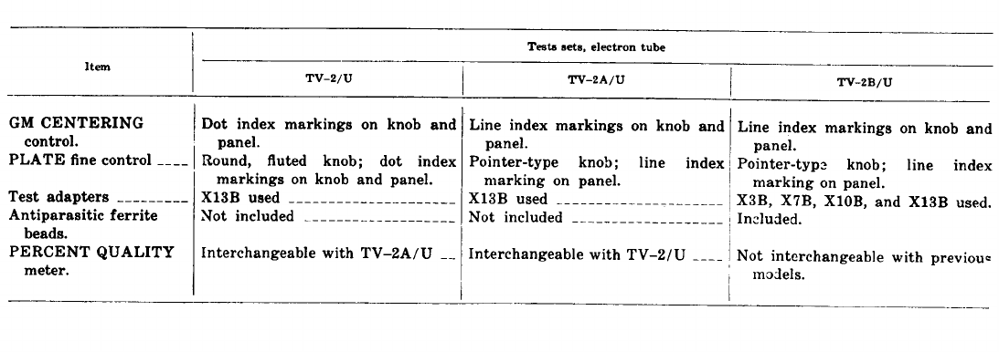
7. Differences in Models
Test Sets, Electron Tube TV-2/U, TV-2A/U, and TV-2B/U
are similar in purpose, operation, and appearance. On some equip-
ments, the FUNCTION switch and the FIL. CONT. SHORT lamp
are marked LEAKAGE VR and SHORT, respectively. Other
external differences among models of the tube tester are shown
below.
8
9

CHAPTER 2
OPERATION
Section I. SERVICE UPON RECEIPT OF EQUIPMENT
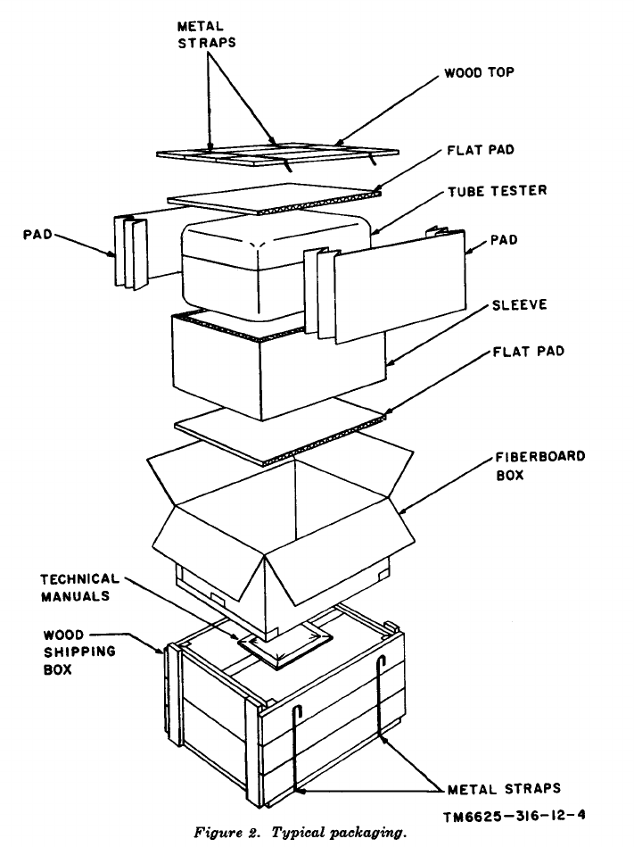
8. Unpacking
a. Packaging Data. When packed for shipment, the tube tester
is cushioned on all surfaces and placed within a water-resistant
fiberboard box. The fireboard box is sealed with water-resistant
tape and placed within a wooden shipping box. Spare tubes, lamps,
and fuses are placed in their designated positions within the tube
tester (figs. 1 and 8), The technical manuals are packed within a
close-fitting bag fabricated of waterproof wrapping paper. The
bag is securely sealed with waterproof pressure-sensitive tape.
The wooden shipping box is strapped only for intertheater ship-
ment. A typical wooden shipping box and its contents are shown
in figure 2.
(1) The inside dimensions of a wooden shipping box that
contains a tube tester is approximately 19¼ by 18¼ by
10¾ inches.
(2) The outside volume of the tube tester packed in a wooden
shipping box is 2.16 cubic feet, and weighs 60 pounds.
b. Removing Contents.
(1) Cut and fold back the metal straps.
(2) Remove the nails from the top with a nailpuller and
remove the wooden top.
(3) Do not attempt to pry off the top; prying may damage the
equipment.
(4) Remove the fiberboard box and cut through the three
edges of the box and remove the contents.
9. Checking Unpacked Equipment
a. Check the equipment for any loss or damage that might have
occurred during shipment. If the equipment has been damaged or
is incomplete, refer to paragraph 2.
b. If the equipment has been used or reconditioned, see whether
it has been changed by a Modification Work Order (MWO). If
10

Section II. OPERATORS CONTROLS AND INDICATORS
10. Damage From Improper Settings
Improper setting of the FILAMENT RANGE switch (fig. 3) or
incorrect operation of the PRESS TO TEST switches may damage
the tube under test. Be sure that all the controls and switches are
set properly before inserting the tube in the socket.
11. Operating Controls and indicators
(fig. 3)
a. Controls.
Control
ON-OFF switch . . . . . . . . . ..........
PRESS TO TEST (switches P1
through P6).
SHORT TEST (6-position rotary
switch ).
FUNCTION (3-position rotary
switch).
Note.
On some equipment
is marked LEAKAGE VR. this switch
Seven SELECTORS switches:
FIL- and FIL+ 12-position
rotary switches.
GRID (12-position rotary switch) -
Function
In ON position, applies ac power to unit.
Depending on type of test selected, de-
pressing one or more switches applies
power to tube under test.
In OPER. position, permits all tests ex-
cept short test. By turning switch
successively through positions V, W,
X, Y, and Z, various tube electrodes
are tested for interelement shorts.
Switch
position
Action
TEST ---------- Permits all types of tube
tests except voltage reg-
ulator and leakage tests.
VR--------------- Permits tests of thyra-
trons and voltage regu-
lator tubes in conjunc-
tion with PRESS TO
TEST P5 switch.
LEAK . . . . Permits determining in-
terelement leakage in
megohms as indicated
by PLATE meter.
Turning each of the filament switches to
one of positions 1 to 9 connects fila-
ment voltage to correspondingly num-
bered base pin of tube under test. (0
is no connection.)
Turning the switches to position A or B
connects filament voltage to A or B
electrical clip, respectively.
When set to one of positions 1 to 9, con-
nects grid bias and signal voltage to
correspondingly numbered base pin of
tube under test. (0 is no connection.)
In A or B, connects grid bias and
signal voltage to A or B electrical clip.
12

Control
PLATE (12-position rotary
switch).
SCREEN (12-position rotary
switch).
CATHODE (12-position rotary
switch).
SUPPRESSOR (12-position rotary
switch).
FILAMENT RANGE (20-position
rotary switch).
FILAMENT fine control ------------
BIAS RANGE (8-position rotary
switch).
BIAS fine control ------------------
PLATE-SCREEN RANGE (12-
position rotary switch).
PLATE fine control------------
SCREEN fine control ---------------
GM-SIGNAL RANGE (6-position
rotary switch).
Function
When set to one of positions 1 to 9, con-
nects plate voltage to correspondingly
numbered base pin of tube under test.
(0 is no connection.) In position A or
B, connects plate voltage to A or B
electrical clip.
When set to one of positions 1 to 9, con-
nects screen voltage to correspondingly
numbered base pin of tube under test.
(0 is no connection.) In position A or
B, connects screen voltage to A or B
electrical clip.
When set to one of positions 1 to 9, con-
nects desired test circuit to cathode of
tube under test through correspond-
ingly numbered base pin or, in position
A or B, connects through A or B elec-
trical clip.
When set to one of positions 1 to 9, con-
nects desired test circuit to suppressor
grid of tube under test through cor-
respondingly numbered base pin or, in
position A or B, through A or B elec-
trical clip.
Selects proper filament voltage between
OFF (0-volt) and 117 (117 volts ac).
Permits fine adjustment of filament volt-
age applied to tube under test.
Selects 5, 10, or 50 volts fixed bias, or
connects biasing resistors as required
when in positions A, B, C, D, or E.
Permits fine adjustment of bias voltage.
When in positions G, H, J, K, M, N, P,
Q, R, or S, connects the proper plate
and screen grid voltage to be used in
the test circuit. (OFF is no connec-
tion.)
Permits fine adjustment of plate voltage.
Permits fine adjustment of screen grid
voltage.
Switch
position Action
A through E-- Connects proper ac sig-
nal voltage to grid of
the tube under test.
F------------- Removes signal voltage
from grid of tube un-
der test to permit cali-
bration of PERCENT
QUALITY meter for
13
Control
Function
SIGNAL-VR control---------------------
Quality SHUNT control --------------
GM CENTERING control ------------
b. Indicators.
Indicator
PERCENT QUALITY meter -------
FILAMENT VOLTS meter ----------
GRID BIAS VOLTS meter -----------
PLATE meter --------------------------
SCREEN VOLTS meter -------------
SIGNAL meter -------------------------
PILOT lamp ------------------------
FIL. CONT. SHORT lamp -------
Note. On some equipments this lamp is
marked SHORT.
Switch
position Action
performance of trans-
conductance (GM)
test.
Permits accurate adjustment of ac signal
level (indicated on the SIGNAL
meter). In test of voltage-regulator
tubes, permits adjustment of maxi-
mum and minimum currents through
the tube (indicated on the PLATE
meter).
When set to the position specified on the
tube test data roll chart, shunts PER-
CENT QUALITY meter with proper
resistance to perform quality (GM)
test.
With GM-SIGNAL RANGE switch in
position F and the quality SHUNT
control set in accordance with tube
test data, permits zero calibration of
the PERCENT QUALITY meter for
transconductance (GM) test.
Function
Indicates transconductance of amplifier
tube under test.
Indicates ac filament voltage supplied to
tube under test.
Indicates grid-bias voltage supplied to
tube under test.
Indicates plate voltage supplied to tube
under test.
Indicates screen grid voltage supplied to
tube under test.
Indicates ac signal level supplied to tube
under test.
Glows when tube tester is connected to
ac power source and power ON-OFF
switch is in ON position.
Glows to indicate short-circuited ele-
ments or filament continuity in tube
under test.
14

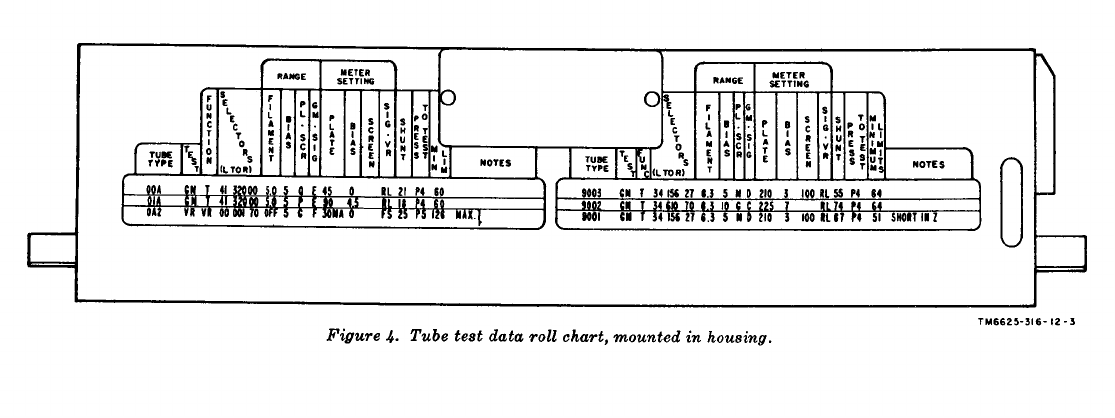
12. Tube Test Data
Tube test data in roll chart form is mounted in a case inside
the cover of Test Set, Electron Tube TV-2(*)/U (fig. 1). The
tube test data roll chart has left- and right-hand sections. The
tube types appear in ascending numerical and alphabetical order
from top to bottom in the left-hand section and from bottom to
top in the right-hand section. Designations on the tube test data
roll chart housing (fig. 4), which appear in duplicate over both
sections of the tube test data roll chart, indicate the tube type,
the switches and controls of the tube tester in the order in which
settings should be made, and the minimum acceptable percentage
of rated transconductance as indicated on the PERCENT
QUALITY meter. The information necessary to set the switches
and controls for any tube type listed on the tube test data roll
chart appear directly below these column headings.
Column
TUBE TYPE-------------
TEST ---------------------
FUNCTION--------------------
SELECTORS (L TO R) ------------
RANGE -----------------------
Description
Tubes that can be tested on the TV-
2(*)/U are listed in numerical and
alphabetical order.
Indicates type of test to be performed,
as follows:
EM-Emission
ER-Electron-ray indicator
GM-Transconductance
LK-Leakage
TH-Thyrathron
VR-Voltage regulator
Indicates setting of FUNCTION switch,
as follows:
L-Leakage
T-Test
VR-Voltage regulator
Indicates setting of each selector switch,
reading from left to right on the tube
tester, as follows:
FIL-
FIL+
GRID
PLATE
SCREEN
CATHODE
SUPPRESSOR
Indicates setting of range controls which
correspond to following subcolumns:
FILAMENT
BIAS
PL.-SCR
GM.-SIG
16

Column
METER SETTING --------------
SHUNT -----------------------
PRESS TO TEST -------------------------
MIN LIM (left
MUM LIMITS section ) MINI-
(right section).
NOTES -----------
Description
Indicates setting of meters, by adjusting
associated fine controls, which corre-
spond to the following subcolumns:
PLATE
BIAS
SCREEN
SIG-VR (set to redline (RL) or full
scale (FS))
Indicates setting of SHUNT control.
Indicates which switch or switches, P1
through P6, should be pressed for the
following tests:
P1-Filament continuity and zero-
ing of PLATE ohmmeter for
interelement leakage test.
P2-Emission of diode tubes.
P3-With P2 emission of multigrid
tubes.
P4-Transconductance.
P5-Voltage regulator and thyra-
tron tubes.
P6-Gas test of amplifier tubes.
Indicates minimum numerical value as
read on PERCENT QUALITY meter
for tube under test or individual sec-
tion of multipurpose tube under test.
Gives special information or adjustments
pertaining to tube under test.
17
Section III. PRELIMINARY OPERATING PROCEDURES
Tube test socket
Tube type tested
13. Operating Precautions
(fig. 3)
a. Do not insert a tube into a test socket until the SELECTORS
switches and the FILAMENT RANGE switch are properly ad-
justed (par. 16).
b. Return all controls to their safety positions (par. 15d) when
the tube tester is turned off.
c. Do not prolong the testing of tubes with filaments that draw
more than 3 amperes.
d. Inspect the bases of seven- and nine-pin miniature tubes for
bent pins before inserting the tube into the test socket. If any
pins are bent, straighten and aline them by inserting the tube
into the proper pin straightener (mounted on the inside of the
cover of the tube tester (fig. 1)) and pressing the tube down
firmly.
14. Tube Test Sockets and Test Adapters
After the controls on the tube tester have been set as directed
in the tube test data roll chart (par. 12), place the tube to be
tested in the proper tube test socket listed below.
a. Tube Test Sockets (fig. 3).
FOUR -----------------------------------------
Four-pin standard tubes.
FIVE ----------------------------------------- Five-pin standard tubes.
LOCTAL -------------------------------------
Loctal base tubes.
SIX --------------------------------------------
Six-pin standard tubes.
MIN. SEVEN ----------------------------------
Seven-pin miniature tubes.
SUB-MIN. EIGHT LONG LEAD_ Eight-pin, long-lead subminiature tubes.
TRANSMITTING SEVEN PIN----------
Seven-pin transmitting tubes.
NOVAL --------------------------------------
Nine-pin miniature tubes.
OCTAL ---------------------------- Octal base tubes.
SEVEN ------------------------------------------
Seven-pin standard tubes.
ACORN ------------------------------------ Acorn tubes.
SUB-MIN. SEVEN ----------------------------
Seven-pin subminiature tubes.
SUB-MIN. EIGHT ----------------------------
Eight-pin subminiature tubes.
b. Test Adapters. A test adapter X13B (fig. 1) is included to
provide a test socket for eight-pin, subminiature, long lead tubes.
Three test adapters (fig. 5) (X3B (eight-pin octal), X7B (nine-
pin noval), and X1OB (seven-pin miniature)) are included with
each TV-2B/U. The test adapters are installed in their corre-
19
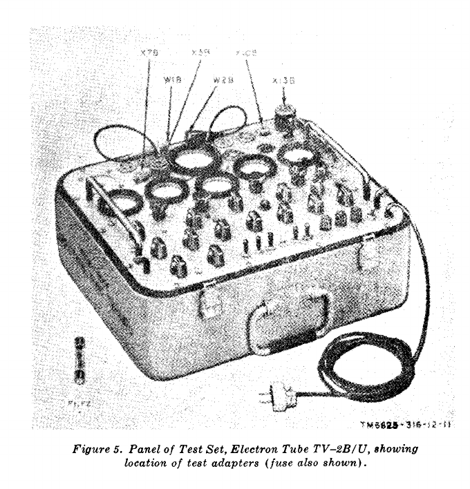
Figure 5.
sponding sockets and receive the wear rather than the permanent
socket. When worn so that satisfactory contact can no longer be
made, the test adapters can be replaced without disconnecting
the leads from their respective test socket.
15. Preliminary Starting Procedure
a. Check the voltage and frequency of the alternating current
(ac) power source to be used for the operation of Test Set, Elec-
tron Tube TV-2(*)/U. The voltage must be between 103.5 and
126.5 volts ac and the frequency between 50 and 1,000 cycles per
second (cps).
Cution: Never connect the TV-2(*)/U to a direct current (dc)
power source.
b. Release the latches and raise the cover of the tube tester.
c. Remove the power cord plug from the dummy power cord
20
receptacle on the panel (fig. 1) and unwind the power cord from
the brackets.
d. Check to see that all controls and switches are in their
power cord safety positions as follows:
Switch or control Safety position
ON-OFF ---------------------------------------- OFF.
SHORT TEST ---------------------------------- OPER.
FUNCTION ------------------------------- TEST.
PRESS TO TEST P1, P2, P3, P4, Neutral
P5, and P6.
FIL and FIL+ ---------------------------- 0.
GRID -------------------------------------------- 0.
PLATE ----------------------------------------- 0.
SCREEN ----------------------------------------- 0.
CATHODE ------------------------------------- 0.
SUPPRESSOR ---------------------------------- 0.
FILAMENT RANGE ------------------------ OFF.
FILAMENT fine control --------------------- Extreme counterclockwise.
BIAS RANGE -------------------------------- 50.
BIAS fine control -------------------------- Extreme counterclockwise.
PLATE-SCREEN RANGE ------------------- OFF.
PLATE fine control --------------------- Extreme counterclockwise.
SCREEN fine control --------------------- Extreme counterclockwise.
SIGNAL-VR fine control -------------------- Extreme counterclockwise.
GM-SIGNAL RANGE ----------------------------------
F.
SHUNT control -------------------------------
0.
GM CENTERING control
------------------------
Midposition (as shown by alinement of
dot on knob with that on panel).
e. Condensed operating instructions are mounted inside the
cover of the tube tester (fig. 1). Revise the condensed operating
instructions for GM TESTING to read as follows:
(1)
(2)
(3)
(4)
(5)
(6)
Perform all operations listed in I through IV.
Depress P4 and reset controls as shown on tube test data
roll chart.
Release P4, set GM-SIGNAL RANGE control to F, and
depress P4.
Set PERCENT QUALITY meter to 0 with GM CEN-
TERING control.
Release P4 and return GM-SIGNAL RANGE control to
tube test data roll chart listing.
Depress P4; if PERCENT QUALITY meter reading is
above value in MIN LIM column, tube is good. Release
P4.
f. Insert the power cord plug into the ac outlet.
21
Section IV. OPERATION UNDER USUAL CONDITIONS
16. Starting Procedure
Note. To start the equipment, first make sure the controls are set as
required by the preliminary starting procedure (par. 15) and then perform
procedures described in a through i below.
a. Locate the type number of the tube to be tested on the tube
test data roll chart mounted inside the cover of the tube tester.
b. Set the seven SELECTORS switches to the positions given
on the tube test data roll chart for the tube under test. Set the
switches in the order in which they appear on the tube test data
roll chart and on the tube tester panel, from left to right, starting
with the FIL-SELECTORS switch on the left-hand side.
Note. The seven SELECTORS switches are interconnected electrically so
that two different voltages cannot be applied to the same pin of the tube
under test at the same time. Thus, by setting the SELECTORS switches
in the order in which the switches are arranged on the panel, short circuits
are avoided.
C. Set the FILAMENT RANGE switch to the position indi-
cated on the tube test data roll chart.
d. Insert the tube to be tested into the proper test socket.
Caution: Be careful when inserting and removing loctal, acorn,
and subminiature tubes from their sockets. Excessive force will
crack the glass seals at the bases of the pins. Exert slight pres-
sure to one side to release the lock of the LOCTAL socket. Use
the pin straighteners mounted on the tube test data roll chart
housing to straighten bent pins of seven- and nine-pin miniature
tubes.
e. If the tube to be tested has a top cap, attach the A or B
electrical clip. Directions as to which clip to use are given in the
NOTES column on the tube test data roll chart unless the NOTES
column is required for other data. In addition, one of the SE-
LECTORS switches will indicate an A or B position. If the A
position is designated, use the A clip; if the B position is desig-
nated, use the B clip.
f. Set the ON-OFF switch to the ON position. The PILOT
lamp should g1ow. Allow at least 1 minute warmup time.
g. Adjust the FILAMENT fine control until the FILAMENT
VOLTS meter pointer indicates the exact filament voltages speci-
fied in the RANGE column of the tube test data roll chart unless
there is a note to the contrary. In the case of a filament voltage
of 0.625, 6.3, 12.6, or 117 volts, adjust the control until the meter
pointer is on the red calibration line on the
h. If the line voltage is low, it may not be
the FILAMENT fine control to indicate the
voltage.When this condition exists, turn
appropriate scale.
possible to adjust
specified filament
the FILAMENT
22
RANGE switch to the next higher position, and then adjust the
control until the correct voltage is indicated on the meter.
i. If the line voltage is high and it is not possible to adjust
the FILAMENT fine control to indicate the specified voltage,
turn the FILAMENT RANGE switch to the next lower position,
and then adjust the control until the correct voltage is indicated
on the meter.
17. Zero Adjustment of PERCENT QUALITY Meter
When the procedures in paragraph 16 have been completed,
adjust the PERCENT QUALITY meter to zero. This adjustment
should be made before testing any tube for transconductance
(GM) as follows:
a. Turn the GM-SIGNAL RANGE switch to the F position.
b. Depress the PRESS TO TEST P4 switch to its locking posi-
tion. Reset the controls to give the exact meter readings specified
in the METER SETTING columns of the tube test data roll chart.
c. Adjust the GM CENTERING control until the pointer of the
PERCENT QUALITY meter is set exactly to zero on the scale.
d. Release the P4 switch.
18. Short Test
a. Perform the operations described in paragraphs 15 and 16.
b. For the TV-2/U, aline the dot on the PLATE fine control with
the dot on the panel. For TV–2A/U and TV–2B/U, aline the
PLATE fine control pointer-type knob with the line index marking
on the panel. This assures that the correct voltage will be applied
to the short test circuit.
c. Turn the SHORT TEST switch slowly from the OPER.
position to V, W, X, Y, and Z, and back to OPER.; at the same
time, tap the tube with a finger and watch the FIL. CONT. SHORT
indicator lamp.
Caution: Do not tap the tubes listed below when testing for
short-circuited elements. Tapping may damage the tube.
1A5GT 1LH4
1A7GT 1LN5
1C5GT 1P5GT
1G4GT 1Q5QT
1G6GT 1S4
1H5GT 1S5
1L4 1T4
1LA4 1T5GT
1LA6 1U4
1LB4 1U5
1LD5 3A4
1LE3 3A5
23
3A6GT3Q4
3B73Q5QT
3D6 3S4
3LF43V4
d. If the lamp burns continuously or glows during tapping in
any one of the five positions of the SHORT TEST switch, the tube
contains short-circuited electrodes. Discard the tube unless an
exception is noted on the tube test data roll chart.
e. Disregard a momentary flash of the FIL. CONT. SHORT
indicator lamp while the SHORT TEST switch is being moved
from one position to the next. This flashing usually is caused by
the charging of a capacitor in the test circuit.
Note. Some tubes normally test as shorted when the SHORT TEST switch
is in certain positions. Before discarding a tube that shows a short, check
the tube test data roll chart NOTES column for information on normal short
indications.
f. When the test is completed, set the ON-OFF switch to the
OFF position, remove the tube under test from the test socket, and
return all switches and controls to their safety positions (par.
15d) .
19. Interelement Leakage Test
Follow the test procedure in a through e below to determine the
interelement leakage (LK) in megohms between electrodes of the
tube under test.
a. Perform the operations described in paragraphs 15 and 16.
b. Operate the FUNCTION switch to the LEAK position. This
position connects the PLATE meter into the circuit to serve as an
ohmmeter for this test only.
c. Set the ohmmeter (PLATE meter) to zero as follows:
(1) Operate the SHORT TEST switch to the V position.
(2) Turn the PLATE fine control to its maximum counter-
clockwise position.
(3) Depress the PRESS TO TEST P1 switch.
(4) With the P1 switch held in its depressed position, adjust
the PLATE fine control until the pointer of the PLATE
meter indicates zero (250 on center scale) on the ohm-
meter (top) scale.
(5) Release the P1 switch.
d. Operate the SHORT TEST switch slowly from the OPER.
position to positions V, W, X, Y, and Z; at the same time, watch
for a deflection of the PLATE meter pointer.
24
(1) An open circuit or infinite leakage between elements will
produce no deflection of the PLATE meter pointer.
(2) A short circuit between two elements will produce a full-
scale deflection of the PLATE meter pointer.
Note. Where the NOTES column indicates a short circuit, full-
scale deflection will appear at those settings.
(3) Read intermediate leakage values on the resistance scale
of the PLATE meter. The amount of leakage is indi-
cated in megohms.
e. When the test is completed, set the ON-OFF switch to the
OFF position, remove the tube under test from the test socket,
and return all switches and controls to their safety positions (par.
15d) .
20. Filament Continuity Test
a. Perform the operations in paragraphs 15 and 16.
b. If the filament continuity test is the only test to be made, set
only the FIL- and the FIL+ SELECTORS switches as indicated
in the tube test data roll chart. Leave the remaining SELECTORS
switches in their safety positions (par. 15d).
c. Operate the SHORT TEST switch to the V position. For the
TV–2/U, aline the dot on the PLATE fine control with the dot on
the panel. For the TV–2A/U, and TV–2B/U, aline the line mark-
ing on the PLATE fine control with the line marking on the panel.
d. Depress the PRESS TO TEST P1 switch.
(1) If the FIL. CONT. SHORT lamp glows, the filament is
good.
(2) If the FIL. CONT. SHORT lamp does not glow, the fila-
ment is open. Discard the tube.
Note. Occasionally a filament will show continuity when cold,
but will open when it warms up. If this condition is suspected,
set the FILAMENT RANGE switch to the normal voltage for the
tube under test, let the tube warm up for several minutes, and
repeat the test.
21. Transconductance Test
a. Perform the operations described in paragraphs 15 and 16.
b. Operate the FUNCTION switch to the TEST position.
c. Operate the PLATE-SCREEN RANGE switch to the position
specified on the tube test data roll chart.
Warning: Do not touch the top cap of a tube under test after
plate voltage has been applied.
25
d. Adjust the PLATE and SCREEN fine controls until the
PLATE and SCREEN VOLTS meters indicate the exact voltages
specified on the tube test data roll chart. Red calibration marks
on both meters facilitate this adjustment.
e. Set the BIAS RANGE switch to the voltage or position
specified on the tube test data roll chart.
f. Adjust the BIAS fine control until the GRID BIAS VOLTS
meter indicates the exact grid-bias voltage specified on the chart.
g. If the bias voltage indication is over 80 percent of full scale
at a low plate voltage setting, it may be difficult to obtain the
required bias voltage. In such a case, use the next higher setting
of the BIAS RANGE switch.
h. Operate the quality SHUNT control to the number given on
the tube test data roll chart.
i. Adjust the PERCENT QUALITY meter to zero (par. 17).
j. Operate the GM-SIGNAL RANGE switch to the position
specified for the quality test.
k. Adjust the SIGNAL-V.R. fine control until the pointer of the
SIGNAL meter is on the red line.
l. Depress the PRESS TO TEST P4 switch to its locking posi-
tion.
m. Read the percent quality for the tube under test on the
PERCENT QUALITY meter.
(1) If the reading is below the minimum limit indicated on
the tube test data roll chart, discard the tube.
(2) If the reading borders on the minimum limit, the tube
may be usable but should be replaced soon.
(3) If the PERCENT QUALITY meter indication is beyond
full scale, the tube may be gassy. Perform the gas test
(par. 22).
n. Release the P4 switch.
Note. A multisection tube may be listed several times on the tube test data
roll chart. If this is the case, reset the SELECTORS switches for each
listing in the tube test data roll chart. Repeat the short test and the trans-
conductance test for each new setting.
o. When a test is completed, set the ON-OFF switch to the OFF
position, remove the tube under test from the test socket, and
return all switches and controls to their safety positions (par.
15d) .
22. Gas Test
Use the following procedures to determine whether an amplifier
26
tube contains excessive gas. When testing a multisection tube,
make the gas test on an amplifier section; it does not apply to diode
sections or to rectifiers.
a. Perform the operations in paragraphs 15 and 16.
b. Operate the FUNCTION switch to the TEST position.
c. Operate the PLATE-SCREEN RANGE switch to the posi-
tion specified on the tube test data roll chart.
Warning: Do not touch the top cap of a tube under test after
plate voltage has been applied.
d. Adjust the PLATE and SCREEN fine controls until the
PLATE and SCREEN VOLTS meters indicate the exact voltages
specified on the tube test data roll chart. Red calibration marks
on the scales of both meters facilitate this adjustment.
e. Operate the BIAS RANGE switch to the voltage or position
specified on the tube test data roll chart.
f. Adjust the BIAS fine control until the GRID BIAS VOLTS
meter indicates the specified voltage.
g. Set the quality SHUNT control to the number given on the
tube test data roll chart, and adjust the PERCENT QUALITY
meter to zero (par. 17).
h. Operate the GM-SIGNAL RANGE switch to the position
specified for the quality test.
i. Adjust the SIGNAL-V.R. fine control until the pointer of
the SIGNAL VOLTS meter is on the red line.
j. Depress the PRESS TO TEST P4 switch to its locking posi-
tion.
k. Depress and hold down the PRESS TO TEST P6 switch.
Depressing the P6 switch may cause the PERCENT QUALITY
meter pointer to move upward or downward on the scale. If the
pointer moves more than three scale divisions in either direction,
the tube contains too much gas for satisfactory operation.
Note. Some tubes develop gas after they have been in operation for a
period of time. When this is suspected to be the case, let the tube remain
under test with operating potentials applied for several minutes before
making the gas test.
l. When the test is completed, set the ON-OFF switch to the
OFF position, remove the tube under test from the test socket,
and return all switches and controls to their safety positions
(par. 15d).
23. Emission Test
Use the following procedure to test the emission (EM) of recti-
fier tubes, diode detectors, and multielement tubes.
27
a. Perform the operations described in paragraphs 15 and 16.
b. Operate the FUNCTION switch to the TEST position.
c. Set the PLATE-SCREEN RANGE switch to the position
specified on the tube test data roll chart.
d. Adjust the PLATE fine control until the PLATE meter in-
dicates the exact voltage specified on the tube test data roll chart.
Red calibration marks on the meter scales facilitate this adjust-
ment.
e. Operate the quality SHUNT control to the number specified
on the tube test data roll chart.
f. Operate the GM-SIGNAL RANGE switch to the position
noted on the tube test data roll chart.
g. For the TV–2/U, aline the dot on the knob of the GM CEN-
TERING control with the dot on the panel. For the TV-2A/U
and TV-213/U, aline the line marking on the GM CENTERING
knob with the line marking on the panel.
h. If the tube under test is a diode, hold down the PRESS TO
TEST P2 switch. If the tube under test is a multigrid tube, hold
down both the P2 and P3 switches.
i. Read the PERCENT QUALITY meter. If the indication is
below the minimum limit given on the tube test data roll chart,
discard the tube. Tubes that border on the minimum limit may be
usable but should be replaced soon.
Note. When testing some diodes, the PERCENT QUALITY meter will
deflect off scale. This is a normal condition when the emission of the tube is
far in excess of that required by tube specifications. If the need for balancing
such a diode is present, reduce the setting of the quality SHUNT control until
the PERCENT QUALITY meter reads 100. Observe the new shunt setting
and use this setting to compare diodes of the same type.
j. When the test is completed, set the ON-OFF switch to the
OFF position, remove the tube under test from the test socket,
and return all switches and controls to their safety positions
(par. 15d).
24. Voltage Regulator and Gas Recifier Test
Use the following procedure to test the voltage regulator (VR)
and gas rectifier tubes under minimum and maximum load con-
ditions. The regulating ability of the tube is computed from the
test results. For testing thyratron tubes, refer to paragraph 26.
a. Perform the operations described in paragraphs 15 and 16.
Set the FILAMENT RANGE and BIAS RANGE switches to the
positions indicated in the tube test data roll chart.
b. Set the PLATE-SCREEN RANGE switch to the position
specified on the tube test data roll chart.
28
c. Set the quality SHUNT control to the number specified on
the tube test data roll chart.
d. Set the FUNCTION switch to the VR position.
e. Turn the SIGNAL-V.R. and the BIAS fine controls to their
extreme counterclockwise (zero) positions.
f. Depress and hold down the PRESS TO TEST P5 switch.
Note the current through the tube as indicated on the PLATE
meter and note the reading of the PERCENT QUALITY meter.
g. With the P5 switch held in its operated position, adjust the
SIGNAL-V. R., PLATE, and SCREEN fine controls until the VR-
50 MA scale of the PLATE meter indicates the minimum load
current through the tube as specified on the tube test data roll
chart. Note the reading of the PERCENT QUALITY meter.
h. With the PRESS TO TEST P5 switch still held in its oper-
ated position, adjust the SIGNAL-V.R. fine control until the VR–
50 MA scale of the PLATE meter indicates the maximum load
current specified on the chart. Note the reading of the PERCENT
QUALITY meter.
i. Determine the regulating ability of a tube by taking the
difference between the maximum and minimum load currents
through the tube as read on the PERCENT QUALITY meter.
If the difference between the two readings is greater than the
maximum difference indicated on the tube test data roll chart,
discard the tube.
Note. A quality SHUNT control setting of 50 is specified for many voltage
regulator tubes. When so specified, the reading on the PERCENT QUALITY
meter indicates directly the voltage drop across the tube under test. The
difference between the voltage drop at minimum and maximum load currents
as read on the PERCENT QUALITY meter then is equal to the regulating
ability of the tube in volts.
j. When the test is completed, set the ON-OFF power switch
to the OFF position, remove the tube under test from the test
socket, and return all switches and controls to their safety posi-
tions (par. 15d).
25. Procedure for Reading Plate Current (Less Than 50 Milliam-
peres) of Triode Tubes
a. Perform the operations indicated in paragraphs 15 and 16.
b. Set all SELECTORS switches as indicated on the tube test
data roll chart with the exception of the PLATE and SCREEN
SELECTORS switches.
c. Set the PLATE selector switch to the 0 position.
d. Set the SCREEN SELECTORS switch to the position desig-
29
ated for the PLATE SELECTORS switch on the tube test data
roll chart.
e. Set the GM-SIGNAL RANGE switch to the F position.
f. Adjust the SCREEN fine control until the voltage specified
on the tube test data roll chart for the PLATE meter is indicated
on the SCREEN VOLTS meter.
Note. It may be necessary to set the PLATE-SCREEN RANGE switch to
a new setting, moving the switch in a counterclockwise direction, so that the
SCREEN VOLTS meter can indicate the voltage specified for the PLATE
meter.
g. Adjust all other fine controls as required on the tube test
data roll chart for the tube under test.
h. Turn the SIGNAL-V.R. fine control to its maximum counter-
clockwise position.
i. Set the FUNCTION switch to the VR position.
j. Set the quality SHUNT control to 0.
k. Depress the PRESS TO TEST P5 switch. Be sure the proper
voltages for the tube being tested appear on all other meters.
Note the reading on the 0- to 50-milliampere (ma) scale on the
PLATE meter.
l. Release the PRESS TO TEST P5 switch.
m. When the test is completed, set the ON-OFF power switch
to the OFF position, remove the tube under test from the test
socket, and return all switches and controls to their safety posi-
tions (par. 15d).
26. Thyratron Test
Use the following procedure to determine the firing potential
of thyratron (TH) tubes. Thyratrons are also called gas triodes
or grid glow tubes. The firing potential may be defined as the grid
voltage at which the tube begins to conduct.
a. Perform the operations indicated in paragraphs 15 and 18.
b. Set the FUNCTION switch to the VR position.
c. Set the PLATE-SCREEN RANGE switch to the position
specified on the tube test data roll chart.
d. Set the quality SHUNT control to the number specified on
the tube test data roll chart.
e. Set the SIGNAL-V.R. fine control to its extreme clockwise
(maximum) position.
f. Depress and hold down the PRESS TO TEST P5 switch.
Note the current through the tube as indicated on the PLATE
meter, and note the reading of the PERCENT QUALITY meter.
30
g. Adjust the SCREEN fine control until the SCREEN VOLTS
meter indicates the voltage specified on the tube test data roll chart
(par. 12).
h. Set the BIAS fine control to its extreme clockwise (maxi-
mum) position.
i. With the PRESS TO TEST P5 switch held in its operated
position, gradually reduce the bias voltage by adjusting the BIAS
fine control until the tube strikes its firing potential. The firing
potential is indicated by a sudden increase in load current shown
on the PLATE meter and by a sudden decrease on the PERCENT
QUALITY meter.
Note. The tube will not conduct (as indicated by an increase in load current
shown by the PLATE meter) until the critical grid-bias voltage is reached.
For example, for a type 2D21W or type 2050W tube, the bias voltage at which
conduction occurs should be between 1.5 and 3.0 volts.
j. The voltage at which the tube strikes is read on the GRID
BIAS VOLTS meter. Record the grid voltage at the instant and
at the point that the pointer starts to deflect. This is the striking
voltage of the tube under test. Repeat the test to confirm the read-
ing. Minimum limits for striking voltages of thyratrons are given
on the tube test data roll chart.
k. When the test is completed, set the ON-OFF power switch
to the OFF position, remove the tube under test from the test
socket, and return all switches and controls to their safety posi-
tions (par. 15d).
27. Electron-Ray Indicator Test
There are two types of electron-ray (ER) indicator tubes that
can be tested with the TV–2(*)/U, Type 6U5 and similar tubes
have a triode section and a single indicator (one shadow). Type
6AF6 and similar tubes have no triode section, but have twin
indicators (dual shadow).Follow the procedure below to check
the opening and closing action of the eyes only. Indicators with
triode sections also must be tested for emission (i below).
a. Perform the operations indicated in paragraphs 15 and 16.
b. Operate the FUNCTION switch to the TEST position.
c, Operate the PLATE-SCREEN RANGE switch to the posi-
tion specified on the tube test data roll chart.
d. Adjust the PLATE and SCREEN fine controls until the
exact voltages specified on the tube test data roll chart are indi-
cated on the corresponding meters.
e. Depress the PRESS TO TEST P4 switch. If the tube is a
single indicator, the indicator should be closed; if the tube is a
twin-indicator tube, such as the 6AD6 or 6AF6, indicator No. 1
should be closed and indicator No. 2 should be open.
31
f. Release the PRESS TO TEST P4 switch.
g. For twin-indicator tubes, operate the SCREEN and SUP-
PRESSOR SELECTORS switches to the positions specified in
the second line of the tube test data roll chart.
h. Again depress the PRESS TO TEST P4 switch. If the tube
is good, the indicator now should be open, or, in the case of twin-
indicator tubes, indicator No. 1 should be open and indicator No. 2
should be closed.
i. Perform an emission test on the triode of electron-ray in-
dicators with triode sections, such as 6U5 (par. 23). The control
settings for the emission test are specified in the third entry of
the same tube on the tube test data roll chart (par. 12).
28. Ballast Tube Test
Test ballast tubes as follows:
a. Perform the operations indicated in paragraph 15.
b. Operate the FIL-SELECTORS switch to the position speci-
fied in the tube test data roll chart for the tube under test. All
other switches and controls should be in their safety positions
(par. 15d).
c. Insert the ballast tube into the appropriate socket.
d. Turn the ON-OFF power switch to the ON position.
e. Turn the SHORT TEST switch to the V position.
f. Depress and hold down the PRESS TO TEST P1 switch.
Operate the FIL+ SELECTORS switch to each of the positions
specified in the tube test data roll chart. The FIL.-CONT.
SHORT lamp should glow in every position noted. If it does not,
discard the ballast tube.
g. Repeat the procedures indicated in b through f above for
each listing of the tube.
29. Indicator Lamp Test
To check an indicator lamp or other lamps with miniature
bayonet or screw-type bases, proceed as follows:
a. OPERATE THE FIL- SELECTORS switch to position 2.
b. Operate the FIL+ SELECTORS switch to position 7.
c. Operate the FILAMENT RANGE switch to the correct
voltage for the lamp under test. This voltage usually is marked
on the lamp base.
d. Operate the ON-OFF power switch to the ON position.
e. Adjust the FILAMENT fine control until the FILAMENT
VOLTS meter indicates the exact voltage specified for the lamp.
32
f. Insert and hold the lamp in the center of the SEVEN socket.
If the lamp is good, it will light with normal brilliancy.
Caution: Do not test glow lamps with the TV-2(*)/U unless
these lamps are supplied with a current-limiting series resistor.
g. When the test is completed, operate the ON-OFF power
switch to the OFF position and return the FIL- and FIL+
SELECTORS switches, the FILAMENT RANGE switch, and
the FILAMENT fine control to their safety positions (par. 15d).
30. Complete Tube Test
As an example of a complete tube test, assume a 6SQ7 tube is
to be tested. The 6SQ7 tube is a twin-diode high-mu triode used
as a combined detector, amplifier, and automatic voltage control
tube in radio receivers. It has an eight-pin octal base. Rotate
the tube test data roll chart until the 6SQ7 appears in the TUBE
TYPE column in the left-hand window of the tube test data roll
chart housing. In addition to tests for short circuits, interelement
leakage, and filament continuity, note that this tube must be tested
three times: to test the transconductance of the triode section, to
measure the emission of diode No. 1, and to measure the emission
of diode No. 2. In addition, the gas content of the tube must be
checked.
a. Preparation. Adjust the tube test data roll chart so the first
line on which 6SQ7 appears is in the center of the window between
the horizontal red lines. Refer to the column headings marked
on the tube test data roll chart housing and proceed as follows:
(1) Perform the operations described in paragraph 15.
(2) Set the FUNCTION switch to TEST (T).
(3) Set the SELECTORS switches to the positions indicated
in the SELECTORS (L TO R) column on the tube test
data roll chart and in the order indicated:
(a) FIL— to 7.
(b) FIL+ to 8.
(c) GRID to 2.
(d) PLATE to 6.
(e) SCREEN to 0.
(f) CATHODE to 3.
(g) SUPPRESSOR to 0.
(4)
(5)
(6)
Set the FILAMENT RANGE switch to the 6.3 position.
Insert the 6SQ7 tube into the OCTAL test socket.
Set the ON-OFF switch to the ON position and allow a
l-minute warmup.
33
(7) Adjust the FILAMENT fine control until the FILA-
MENT VOLTS meter needle indicates 6.3 volts.
b. Short Test. To perform the short test (par. 18) on the
6SQ7 tube, proceed as follows:
(1)
(2)
(3)
For the TV–2/U, aline the dot on the PLATE fine control
with the dot on the panel. For the TV-2A/U and TV-
2B/U, aline the PLATE fine control pointer-type knob
with the line index marking on the panel.
Turn the SHORT TEST switch slowly from the OPER.
position to V, W, X, Y, and Z, and back to OPER.; at
the same time, tap the tube with a finger and watch the
FIL. CONT. SHORT indicator lamp.
If the lamp glows continuously or glows during tapping
in any of the five positions of the SHORT TEST switch,
the tube contains a short circuit. Discard the tube. If
there is no short circuit, proceed with the next test.
c. Interelement Leakage Test. To perform the test for interele-
ment leakage (par. 19) on the 6SQ7 tube, proceed as follows:
(1)
(2)
(3)
(4)
(5)
Set the FUNCTION switch to the LEAK position.
Set the PLATE meter, which is functioning as an ohm-
meter for this test, to zero (par. 19c).
Turn the SHORT TEST switch slowly from the OPER.
position to V, W, X, Y, and Z; at the same time watch
for a deflection of the PLATE meter pointer.
An open circuit or zero leakage between elements will
produce no deflection of the PLATE meter pointer. A
short circuit between elements will produce a full-scale
deflection of the pointer. Read intermediate values on
the resistance scale of the PLATE meter. If there is no
leakage, proceed with the next test.
Set the FUNCTION switch to the TEST position.
d. Filament Continuity Test. Proceed as outlined below to de-
termine whether the filament of the 6SQ7 tube is open (par. 20).
The FIL- and FIL+ SELECTORS switches are set as indicated
in the tube test data roll chart, at 7 and 8, respectively.
(1)
(2)
(3)
(4)
Set the SHORT TEST switch to the V position.
Depress the PRESS TO TEST P1 switch.
If the FIL. CONT. SHORT lamp glows, the filament is
good. If the lamp does not glow, the filament is open.
Discard the tube. If the filament is good, however, pro-
ceed to test the transconductance of the triode section.
Set the SHORT TEST switch to OPER.
34
e. Measurement of Transconductance. To test the transcon-
ductance of the triode section of the 6SQ7 tube, proceed as outlined
below. The FUNCTION switch and all SELECTORS switches
are set as in a (2) through (7) above.
(1) Set the PLATE-SCREEN RANGE switch to the J posi-
tion.
(2) Adjust the PLATE fine control until the PLATE meter
indicates 225 volts.
(3) Set the BIAS RANGE switch to the 5 position.
(4) Adjust the BIAS fine control until the GRID BIAS
VOLTS meter indicates 2 volts.
(5) Turn the SHUNT control to 90.
(6) Adjust the PERCENT QUALITY meter to zero (par.
17).
(7) Set the GM-SIGNAL RANGE switch to D.
(8) Adjust the SIGNAL-V.R. control until the SIGNAL
meter pointer is on the red line.
(9) Depress the PRESS TO TEST P2 switch to its locking
position. Read the percent quality of the 6SQ7 tube on
the PERCENT QUALITY meter. If the reading is below
the minimum limit of 25, discard the tube; if it borders
on 25, the tube may be used but should be replaced soon.
If the meter pointer is beyond full scale, test the tube
for gas.
f. Test for Excessive Gas. To test the tube for gas, proceed as
outlined below. The FUNCTION switch and all SELECTORS
switches and range switches are set as in e above, and the FILA-
MENT VOLTS meter indicates 6.3 volts.
(1) Depress the PRESS TO TEST P2 switch to its locking
position.
(2) Depress and hold down the PRESS TO TEST P6 switch.
If the pointer of the PERCENT QUALITY meter re-
mains at 25 or near 25, the tube does not contain exces-
sive gas.If the pointer moves more than three scale
divisions in either direction, however, the tube contains
too much gas for satisfactory operation.
g. Measurement of Emission (Diode No. 1). To measure the
emission of diode No. 1, adjust the tube test data roll chart so the
second line on which the 6SQ7 tube appears is between the hori-
zontal red lines. The FUNCTION switch, all SELECTORS
switches except the PLATE switch, and the PLATE-SCREEN
35
RANGE switch are set as in a(2) through (4) above, and the
FILAMENT VOLTS meter indicates 6.3 volts,
(1) Set the PLATE switch to the 5 position.
(2) Set the PLATE-SCREEN RANGE switch to the S posi-
tion.
(3) Adjust the PLATE fine control until the PLATE meter
indicates 20 volts ac.
(4) Turn the quality SHUNT control to 90.
(5) Set the GM-SIGNAL RANGE switch to the A position.
(6) For the TV-2/U, aline the dot on the knob of the GM
CENTERING control with the dot on the panel. For
the TV-2A/U and TV–2B/U, aline the line marking on
the GM CENTERING control with the line marking on
the panel.
(7) Depress the PRESS TO TEST P2 switch and read the
PERCENT QUALITY meter. If the indication is less
than the minimum limit of 25, discard the tube. If the
indication is satisfactory, measure the emission of diode
No. 2.
h. Measurement of Emission (Diode No. 2). To measure the
emission of diode No. 2, adjust the tube test data roll chart so
the third line on which the 6SQ7 tube appears is between the
horizontal red lines. The FUNCTION switch, all SELECTORS
switches except the PLATE switch are set as in g above, and the
FILAMENT VOLTS meter indicates 6.3 volts.
(1) Set the PLATE switch to the 4 position.
(2) With the PLATE-SCREEN RANGE switch on S, ad-
just the PLATE fine control until the PLATE meter
indicates 20 volts ac.
(3) The quality SHUNT control remains on 90.
(4) The GM-SIGNAL RANGE switch remains on S.
(5) For the TV-2/U, aline the dot on the knob of the GM
CENTERING control with the dot on the panel. For
the TV-2A/U and TV-2B/U, aline the line marking on
the GM CENTERING control with the line marking on
the panel.
(6) Depress the PRESS TO TEST P2 switch and read the
PERCENT QUALITY meter. If the indication is less
than the minimum of 25, discard the tube. If the indica-
tion is satisfactory, the tube is good.
36
31. Stopping Procedure
a. Set the ON-OFF switch to the OFF position.
b. Remove the tube from the test socket.
c. Return all controls to their safety positions (par. 15d).
d. Remove the power cord from the power source, wind the
power cord around the brackets on the panel, and insert the plug
into the dummy power cord receptacle (fig. 1). Close the cover of
the case, and latch the luggage-type fasteners.
37

CHAPTER 3
OPERATOR’S MAINTENANCE
32. General
The following is a list of maintenance duties normally performed
by the operator of Test Set, Electron Tube TV–2(*)/U. These
procedures do not require special tools or test equipment.
a. Preventive maintenance (par. 33).
b. Visual inspection (par. 34).
c. Operational check (par. 35b).
d. Replacement of defective lamps (par. 39b).
e. Replacement of defective fuses (par. 39a).
f. Checking cable connection.
g. Replacement of defective electron tubes (pars. 36 and 37).
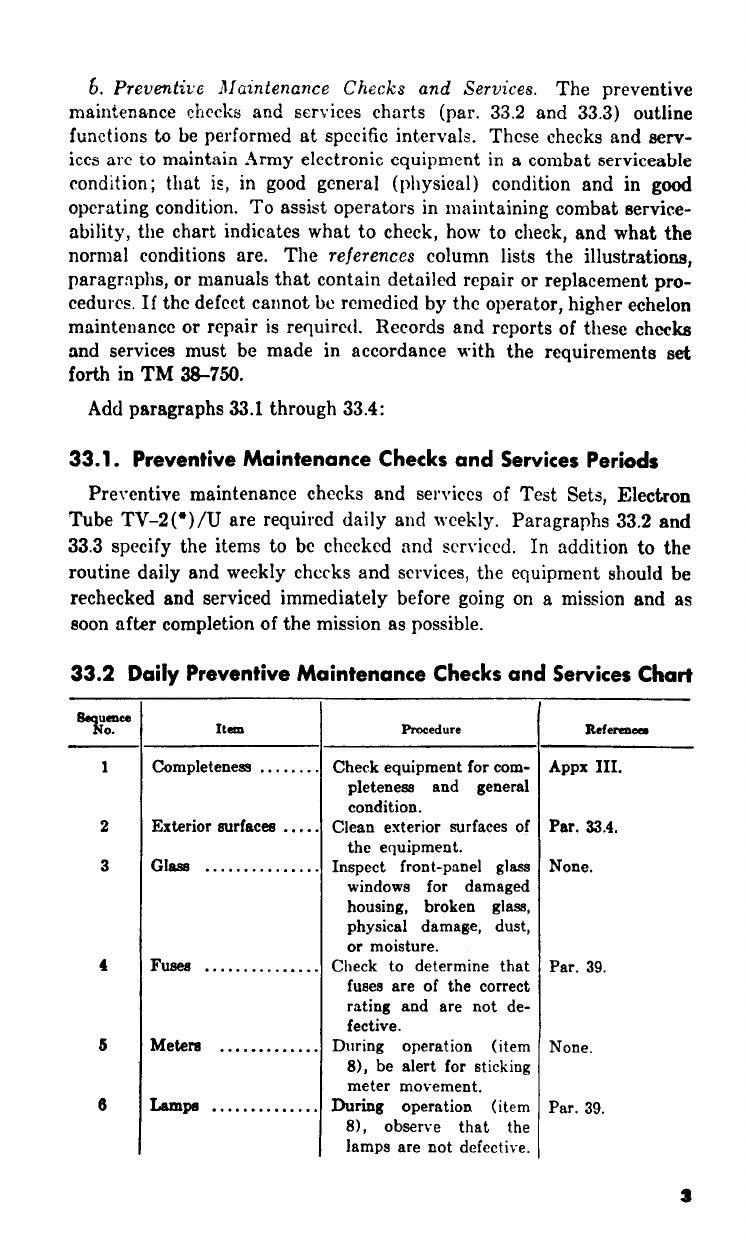
33. Preventive Maintenance
a. DA Form 11–266. DA Form 11–266 (figs. 6 and 7) is a
preventive maintenance checklist to be used by the operator.
Items not applicable to the tube tester are lined out in figure 7.
References in the ITEM block in figure 7 are to paragraphs that
contain additional maintenance information pertinent to the par-
ticular item. Instructions for the use of the form appear on the
form.
b. Items. The information shown below supplements DA Form
11-266. The item numbers correspond to the ITEM numbers on
the form.
Item
Maintenance procedures
1
3
5
Use a clean cloth to remove dust, dirt, moisture, and grease from
the case and front panel. If necessary, wet the cloth with
Cleaning Compound (Federal stock No. 7930–395-9542 ) and then
wipe the parts with a dry, clean cloth.
All control knobs should work smoothly, be tight on the shafts, and
should not bind. Tighten all loose knobs and be sure that the
knobs do not rub against the panel.
Repair any cuts in the power cord insulation by covering them with
rubber tape and then with friction tape.
Warning: Cleaning compound is flammable and its fumes are toxic. Do
not use near a flame; provide adequate ventilation.
38

34. Visual Inspection
a. When the equipment fails to perform properly, turn off the
power and check for the conditions listed below. Do not check any
item with the power on.
(1)
(2)
(3)
(4)
(5)
(6)
Worn, broken, or disconnected power cord or connector.
Improperly connected electrical clips.
Burned-out or improperly seated fuses.
Defective or loose switch knobs. Operate the switches
to be sure there is a definite stop at each position indi-
cated on the panel.
Loose control knobs. Check the knobs by hand.
Improperly seated indicator lamps.
b. If the above checks do not locate the trouble, proceed to the
operational checklist (par. 35).
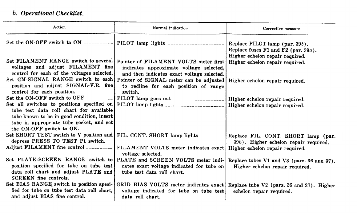
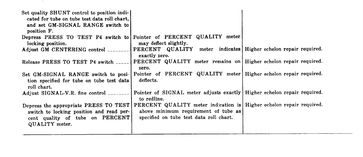
35. Operational Checklist
a. General. The operational checklist provides a procedure for
systematically checking equipment performance. All corrective
measures that the operator can perform are given in the Correc-
tive measures column. When using the checklist, start at step 1
and follow each step in order. If the corrective measures indicated
do not repair the equipment, troubleshooting is required by higher
echelon. Note on the repair tag how the equipment performed and
the corrective measures taken. Perform the steps in b below.
41
43
36. Removal and Replacement of Chassis
a. Removal.
(1) Unsnap the latches and open the cover of the tube tester.
(2) Remove the 14 screws that secure the front panel to the
case.
(3) Lift the panel and the chassis from the case by the han-
dles mounted on the panel.
(4) Slowly lift the tube tester case upward until it is clear
of the chassis.
b. Replacement.
(1)
(2)
(3)
Position the tube tester case so that the handle is for-
ward.
Carefully lower the tube tester into the case. Be sure
that no wires are caught between the front panel and
the edge of the case.
Replace the screws that secure the front panel to the
case.
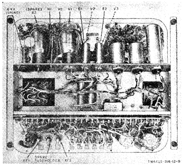
Figure 8. Test Set, Electron Tube TV-2(*)/U, rear view of Chassis.
44
37. Tube Replacement
(fig. 8)
When trouble occurs,
control settings before
suspected, use the tube
the tubes.
check the power cord connection and the
removing any tubes. If tube failure is
substitution method (a below) to check
Caution: Do not rock or rotate a tube when removing it from
a socket; pull it straight out with a tube puller.
a. Tube. Substitution Method. Replace a suspected tube (b
below) with a new tube. If the equipment still does not work,
remove the new tube and put back the original tube. Repeat this
procedure with each suspected tube until the defective tube is
located.
b. Replacing Tubes in Test Set, Electron Tube TV-2(*)/U.
Check the tubes in the tube tester as follows:
(1)
(2)
(3)
(4)
(5)
(6)
(7)
(8)
Remove the chassis from the case (par. 36).
Remove the shields of the 6X4 or 6X4W tubes (V2 and
V3) by pressing down on the shield and rotating coun-
terclockwise until it is released.
Release the retainer of the 83 tube (V1) by pressing
down on the spring which engages the threaded portion
of the supporting stud; remove the retainer from the
tube.
Use a tube puller to remove the tube. If a tube puller is
not available, allow the tube to cool, and then grasp it,
and pull the tube straight up.
If a tube marking has become illegible, label the tube as
soon as it is removed.
Replace the tube (a above) with one of the running
spares.
Set the tube (or a replacement) in the socket and secure
it (by replacing tube retainer or shield).
Replace the chassis in the case (par. 36b).
38. Preferred-Type Tubes
A preferred-type electron tube, type 6X4W, has been developed
as a direct replacement for nonpreferred-type 6X4. The 6X4W
tube is used in the power supply. When replacement of a 6X4
type tube is necessary, replace it with a 6X4W type tube. Do not
substitute a 6X4 tube for a 6X4W tube.
45
39. Replacement of Fuses and Lamps
The two fuses (F1 and F2) and the two glowlamps (11C and
12C) are removable from the front panel of the tube tester.
a. Replacement of Fuses. Fuses F1 and F2 are 3-ampere, 250-
volt, ¼- by 1¼-inch, cartridge-type fuses (fig. 5). To remove a
fuse, press the fuseholder cap and turn it counterclockwise. Re-
move the cap, and then remove the fuse from its holder.
Caution: The fuses are rated at 3 amperes each. When replac-
ing a fuse, be careful to use a fuse of the same rating.
b. Replacement of Lamps. Lamps 11C and 12C are glowlamps
(fig. 1) with miniature-bayonet bases. To remove a glowlamp,
unscrew the indicator light lens, press the lamp inward and
rotate it counterclockwise, and withdraw the glowlamp from its
socket.
46

CHAPTER 4
ORGANIZATIONAL MAINTENANCE
40. General
Organizational maintenance of the tube tester is limited to
preventive maintenance (par. 42) and to the replacement of the
test adapters (fig. 10), electrical plug connector, electrical clip,
insulator clip, knobs (04 through 031, fig. 1), indicator light lens,
and electron tube retainer and shield. The operating instructions
for the tube tester are contained in paragraphs 13 through 31.
41. Tools and Materials Required
The tools and materials required for organizational maintenance
are as follows:
a. Tools. The only tools required are those tools normally avail-
able to the repairman-user because of his assigned mission.
b. Materials.
(1) Cleaning compound.
(2) Cleaning cloth.
(3) Sandpaper, fine.
42. Preventive Maintenance
a. DA Form 11–266. DA Form 11-266 (fig. 9) is a preventive
maintenance checklist to be used by the second echelon. Items not
applicable to the equipment are lined out in the figure. References
to the ITEM block in the figure are to paragraphs that contain
additional maintenance information pertinent to the particular
item. Instructions for the use of the form appear on the form.
b. Items. The information shown in this subparagraph is sup-
plementary to DA Form 11-266. The item numbers correspond
to the ITEM numbers on the form.
Warning: Disconnect all power before performing the follow-
ing operations. After power is disconnected, some capacitors still
may retain dangerous voltages. Before touching exposed electri-
cal parts, short-circuit the parts to ground. When maintenance
is completed, replace the equipment in its case, reconnect the
power, and check for satisfactory operation.
47

Item
Maintenance procedures
12
See that the electron tube shields for V2 and V3 are firmly in
position and secure. See that the electron tube retainer for V1
is clamped tight.
19
Inspect fixed capacitors on the underside of the tube tester chassis
for leaks, bulges, and discoloration.
43. Visual Inspection
Before operating the equipment, inspect it. Inspection will save
repair time and may also avoid further damage. Inspect the fol-
lowing for obvious defects:
a. The seating of all tubes in their sockets.
b. Wiring connections on the terminal board.
c. Wiring connections to the switches and meters on the front
panel.
44. Equipment Performance Checklist
a. General. The equipment performance checklist provides a
procedure for systematically checking equipment performance.
All corrective measures that the second echelon repairman can
perform are given in the Corrective measure column. When using
the checklist, start at the beginning and follow each step in order.
If the corrective measures indicated do not fix the equipment,
troubleshooting is required by higher echelon. Note on the repair
tag how the equipment performed and the corrective measures
that were taken.
b. Procedure. Place the tube tester in operation as shown in
the checklist in c below.
48
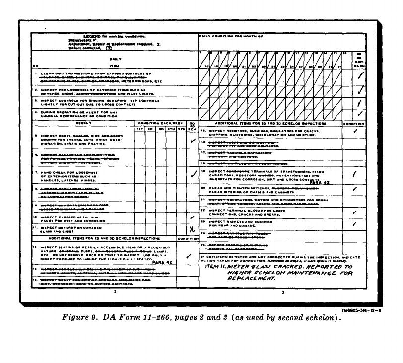
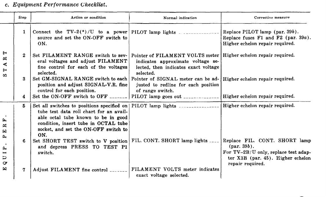
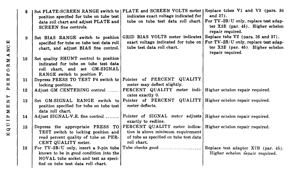
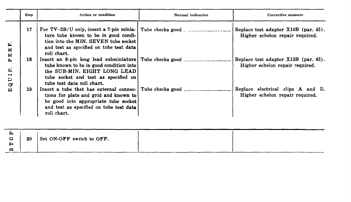
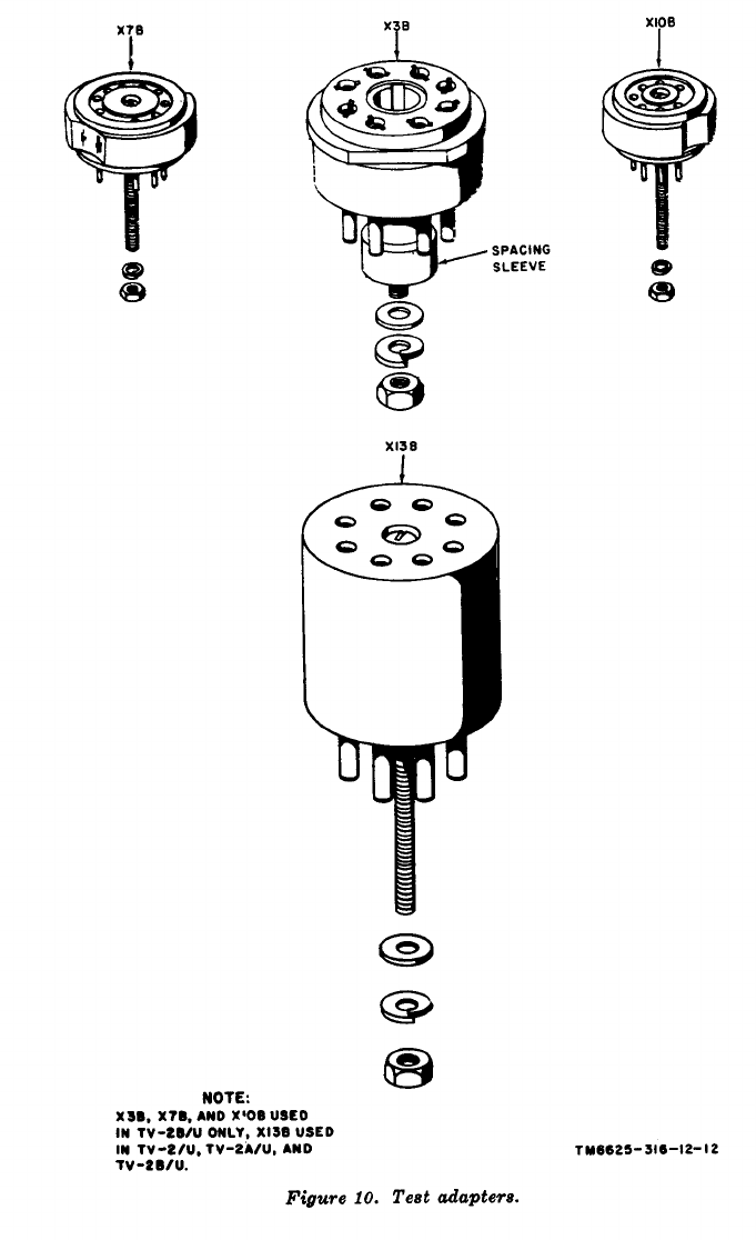
45. Replacement of Test Adapters
(fig. 10)
Replace test adapter X13B (used in TV-2/U, TV-2A/U, and
TV-2B/U) and test adapters X3B, X7B, and X10B (used in TV-
2B/U only) as follows:
a. Removal.
(1) Remove the tube tester chassis (par. 36) from the case.
(2) Remove the hexagonal nut from the threaded stud of the
test adapter to be replaced. Remove the spacing sleeve
when replacing test adapter X3B.
(3) Remove the test adapter from the test socket.
b. Replacement.
(1) Plug the adapter into its corresponding test socket. Be
sure to place the spacing sleeve over the threaded stud
of test adapter X3B.
(2) Replace and tighten the hexagonal nut.
(3) Replace the tube tester chassis in the case.
54

CHAPTER 5
SHIPMENT, LIMITED STORAGE, AND DEMOLITION
TO PREVENT ENEMY USE
Section I. SHIPMENT
46. Disassembly of Equipment
a. Operate all switches and
AND LIMITED STORAGE
their controls to their safety posi-
tions (par. 15d) and disconnect the tube tester from the ac power
supply.
b. Remove the power cord plug from the ac source.
c. Wind the power cord around the brackets on the front panel
and insert the plug into the dummy power cord receptacle that
is mounted on the front panel.
d. Close the case and latch it securely.
47. Repackaging for Shipment or Limited Storage
(fig. 11)
The exact procedure for repackaging depends on the material
available and the conditions under which the equipment is to be
shipped or stored. Adapt the procedures outlined below whenever
circumstances permit. The information concerning the original
packaging (pars. 8 and 9) will also be helpful.
a. Material Requirements. The following materials are required
for packaging the tube tester.For stock numbers of materials,
consult SB 38-100.
Material Quantity
Waterproof wrapping paper ---------------------------------
Fiberboard, corrugated, single-face (flexible) ------------------
Tape, pressure-sensitive adhesive, waterproof (3-inch) ---------------
Tape, paper, gummed (sealing and securing) (3-inch) __________
Strapping, flat, steel
(
5
/
8
-
x 0.02-inch) _ __ __ ____________
Strapping seals -------------------------------------------------------
Wooden shipping box (19¼ x 18¼ x 10 inches inside dimen-
sions).
18 sq ft
35 sq ft
12 ft
10 ft
13 ft
2 each
1 ea
55
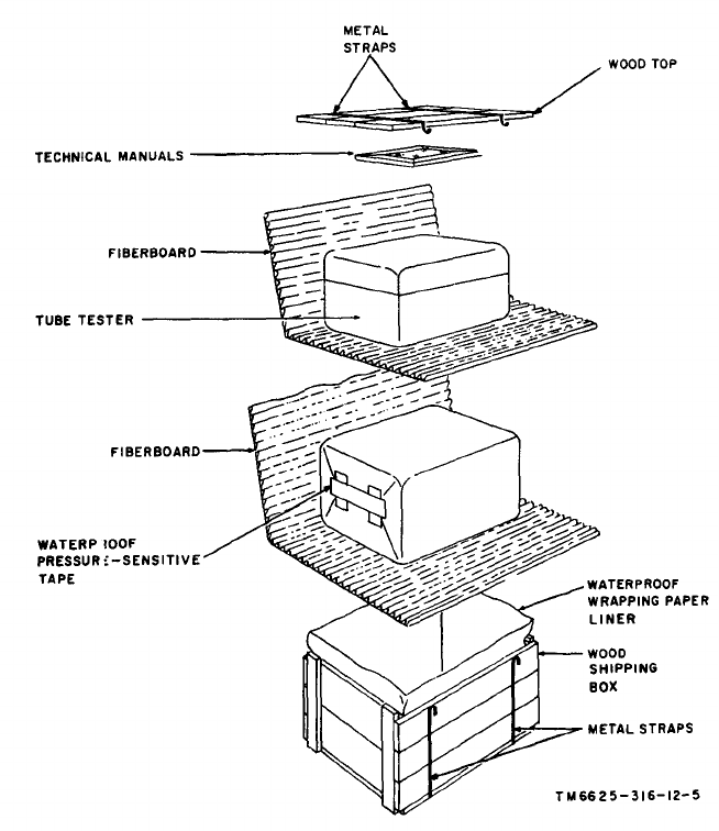
b. Packaging.
(1)
(2)
(3)
Package each technical manual within a close-fitting
bag fabricated of waterproof paper. Seal each bag with
waterproof pressure-sensitive tape.
Running spares are stored in designated positions on
the inside cover and chassis (figs. 1 and 8) of the tube
tester.
Package the tube tester in a double wrap of flexible
corrugated fiberboard. Secure the ends of the package
with waterproof pressure-sensitive tape.
Figure 11. Field repackaging diagram.
56
c. Packing.
(1)
(2)
(3)
(4)
(5)
(6)
Line the wooden shipping box with waterproof wrapping
paper.
Place the wrapped tube tester in the wooden shipping
box.
Seal the waterproof wrapping paper liner with water-
proof pressure-sensitive tape.
Place the wrapped technical manuals on top of the sealed
waterproof wrapping paper liner and secure them with
waterproof pressure-sensitive tape.
Nail the wooden cover in place.
For intertheater shipment, secure the wooden shipping
box with metal strapping.
Section II. DEMOLITION OF MATERIEL TO PREVENT
ENEMY USE
48. Authority for Demolition
The destruction procedures outlined in paragraph 49 will be
used to prevent the enemy from using or salvaging this equipment.
Demolition of the equipment will be accomplished only upon the
order of the commander.
49. Methods of Destruction
Any or all of the methods of destruction given below may be
used. The time available will be the major determining factor
for the methods to be used when destruction of the equipment is
undertaken. The tactical situation also will determine in what
manner the destruction order will be carried out.
a. Smash. Smash meters, switches and controls, the instrument
panel and chassis, tubes, capacitors, resistors, transformers, the
roll chart housing, and the case; use sledges, axes, handaxes, pick-
axes, hammers, crowbars, or heavy tools.
b. Cut. Cut cords and wiring; use axes, handaxes, or machetes.
Warning: Be extremely careful with explosive and incendiary
devices. Use these items only when the need is urgent.
c. Burn. Burn cords, wiring, the tube test data roll chart, and
technical manuals; use gasoline, kerosene, oil, flamethrowers, or
incendiary grenades.
d. Bend. Bend the panel, case, and chassis.
e. Disposal. Bury or scatter the destroyed parts in slit trenches,
foxholes, or other holes, or throw them into streams.
57

APPENDIX I
REFERENCES
Following is a list of references applicable and available to
the operator and unit repairman of Test Set, Electron Tube
TV-2(*)/U:
FM 21-5
FM 21-6
FM 21-30
SB 38-100
AR 320-5
AR 320-50
TM 11-6625-
316-12P
Military Training.
Techniques of Military Instruction.
Military Symbols.
Preservation, Packaging, and Packing Ma-
terials, Supplies, and Equipment Used by
the Army.
Dictionary of United States Army Terms.
Authorized Abbreviations and Brevity Codes.
Operator’s and Organizational Maintenance
Repair Parts and Special Tools List and
Maintenance Allocation Chart for Elec-
tron Tube Test Sets TV-2/U, TV-2B/U,
and TV-2B/U.
58

APPENDIX II
MAINTENANCE ALLOCATION
1. Scope
a. This appendix assigns maintenance functions and repair
operations to be performed by the lowest appropriate mainte-
nance echelon. It also specifies the tools and other equipment
authorized at each echelon to perform the assigned maintenance
functions.
b. Columns in the maintenance allocation chart are as follows:
(1) Part or component. This column shows only the no-
menclature or standard item name. Additional descrip-
tive data are included only where clarification is nec-
essary to identify the part. Components and parts com-
prising a major end item are listed alphabetically.
Assemblies and subassemblies are in alphabetical se-
quence with their components listed alphabetically im-
mediately below the assembly listing.
(2) Maintenance function. This column indicates the various
maintenance functions allocated to the echelon capable
of performing the operations.
(a) Service. To clean, to preserve, and to replenish fuel
and lubricants.
(b) Inspect. To verify serviceability and to detect incipient
electrical or mechanical failure by scrutiny.
(c) Test. To verify serviceability and to detect incipient
electrical or mechanical failure by use of special
equipment such as gages, meters, and other test de-
vices.
(d) Replace. To substitute service assemblies, subassem-
blies, and parts for unserviceable components.
(e) Repair. To restore an item to serviceable condition
through correction of a specific failure or unserviceable
condition. This function includes but is not limited
to, inspecting, cleaning, preserving, adjusting, replace
ing, welding, riveting, and straightening.
(f) Rebuild. To restore an item to a standard as near as
possible to original or new condition in appearance,
performance, and life expectancy. This is accomplished
59
(3)
(4)
(5)
through the maintenance technique of complete dis-
assembly of the item, inspection of all parts or com-
ponents, repair or replacement of worn or unservice-
able elements using original manufacturing toler-
ances and/or specifications and subsequent reassembly
of the item.
1st, 2d, 3rd, 4th, 5th echelon. The symbol X indicates the
echelon responsible for performing that particular main-
tenance operation, but does not necessarily indicate that
repair parts will be stocked at that level. Echelons higher
than the echelon marked by X are authorized to perform
the indicated operation.
Tools required. This column indicates codes assigned to
each individual tool equipment, test equipment, and
maintenance equipment referenced. The grouping of
codes in this column of the maintenance allocation chart
indicates the tool, test, and maintenance equipment re-
quired to perform the maintenance function.
Remarks. Entries in this column will be utilized when
necessary to clarify any of the data cited in the preceding
columns.
c. Columns in the allocation of tools for maintenance functions
are as follows:
(1)
(2)
(3)
Tools required for maintenance functions. This column
lists tools, test, and maintenance equipment required to
perform the maintenance functions.
1st, 2nd, 3rd, 4th, 5th echelon. The dagger (†) symbol in-
dicates the echelons allocated the facility.
Tool code. This column lists the tool code assigned.
2. Maintenance by Using Organizations
When this equipment is used by Signal services organizations
organic to the theater headquarters or communication zones to pro-
vide theater communications, those maintenance functions
allocated up to and including fourth echelon are authorized to the
organization operating this equipment.
3. Mounting Hardware
The basic entries of the maintenance allocation chart do not
include mounting hardware such as screws, nuts, bolts, washers,
brackets, clamps, etc.
60

APPENDIX III
BASIC ISSUE ITEMS LIST
Section I. INTRODUCTION
1. Scope
a. General. This appendix lists items supplied for initial opera-
tion and for running spares. The list includes parts and material
issued as part of the major end item, and all items authorized
for basic operator maintenance of the equipment. End items of
the equipment are issued on the basis of allowances prescribed in
equipment authorization tables and other documents that are a
basis for requisitioning.
b. Columns. The columns areas follows:
(1)
(2)
(3)
(4)
(5)
(6)
(7)
(8)
Source, maintenance, and recoverability code. Not used.
Federal stock number. This column lists the 11-digit
Federal stock number.
Designation by model. Not used.
Description. Nomenclature or the standard item name
and brief identifying data for each item are listed in
this column. When requisitioning, enter the nomencla-
ture and description.
Unit of issue. The unit of issue is the supply term by
which the individual item is counted for procurement,
storage, requisitioning, allowances, and issue purposes.
Expendability. Expendable items are indicated by the
letter X; nonexpendable items are indicated by NX.
Quantity authorized. Under “Items Comprising an
Operable Equipment,” the column lists the quantity of
items supplied for the initial operation of the equip-
ment. Under “Running Spares and Accessory Items”,
the quantities listed are those issued initially with the
equipment as spare parts. The quantities are authorized
to be kept on hand by the operator for maintenance of
the equipment.
Illustration. The “Item No.” column lists the reference
symbols used for identification of the items in the illustra-
tion or text of the manual. The numbers in the “Figure
61

No.” column refer to the illustrations where the part is
shown.
2. Critical Items
A zero slash (ø) in the “Description” column indicates items
that are expected to fail during the first year; also items that will
make the equipment inoperative if they fail.
62
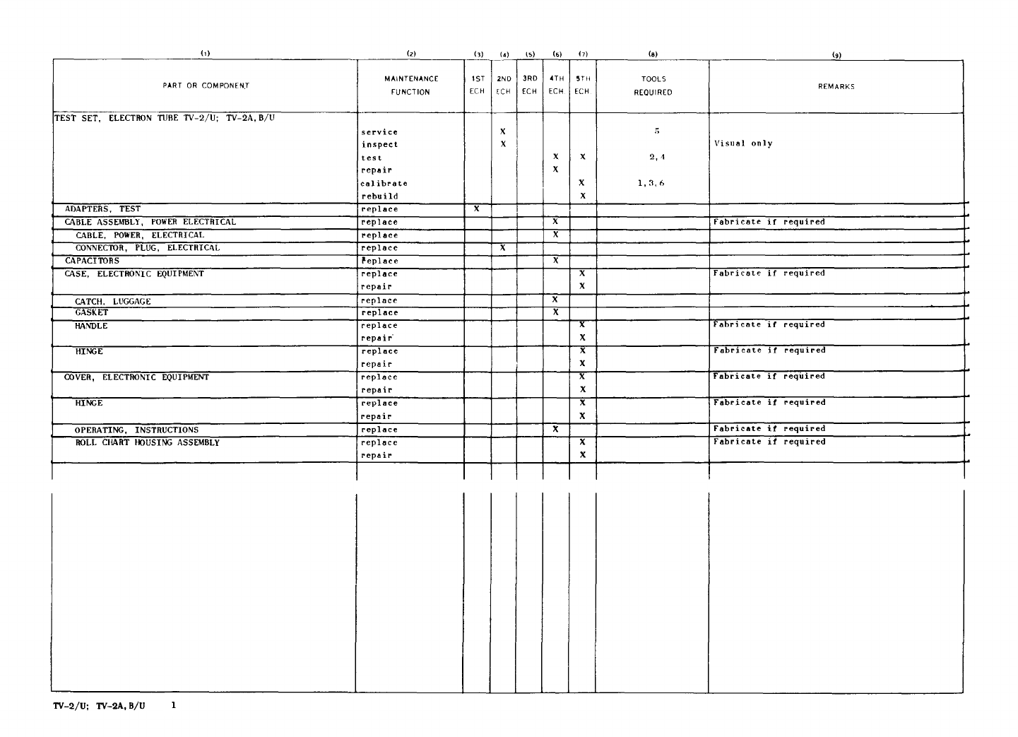
1
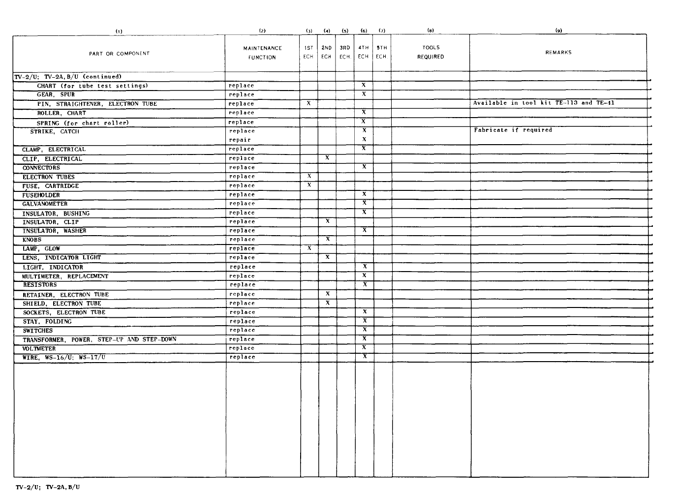
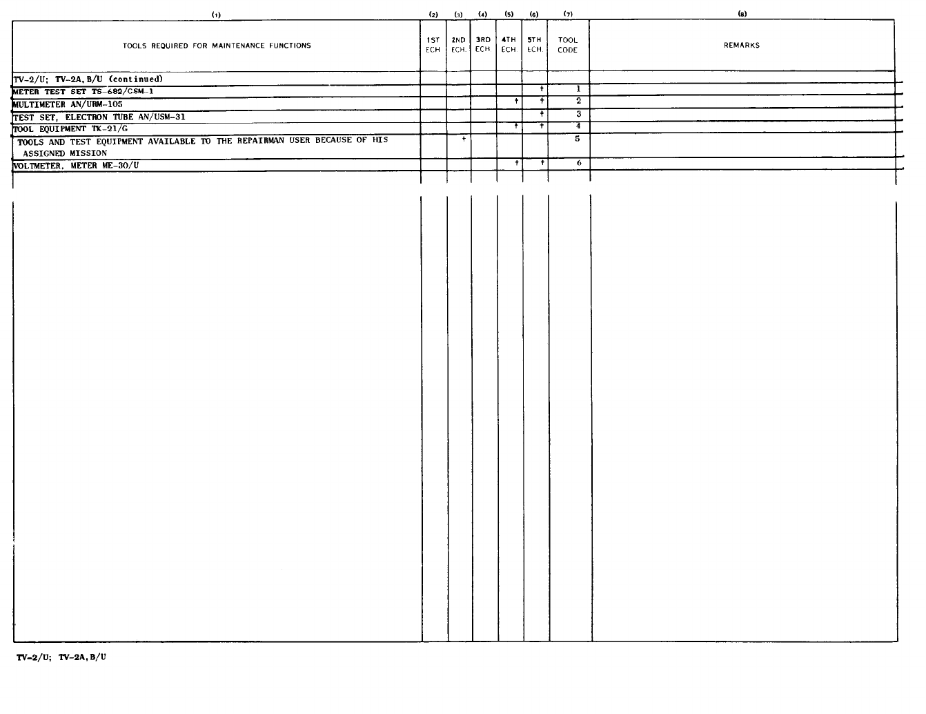
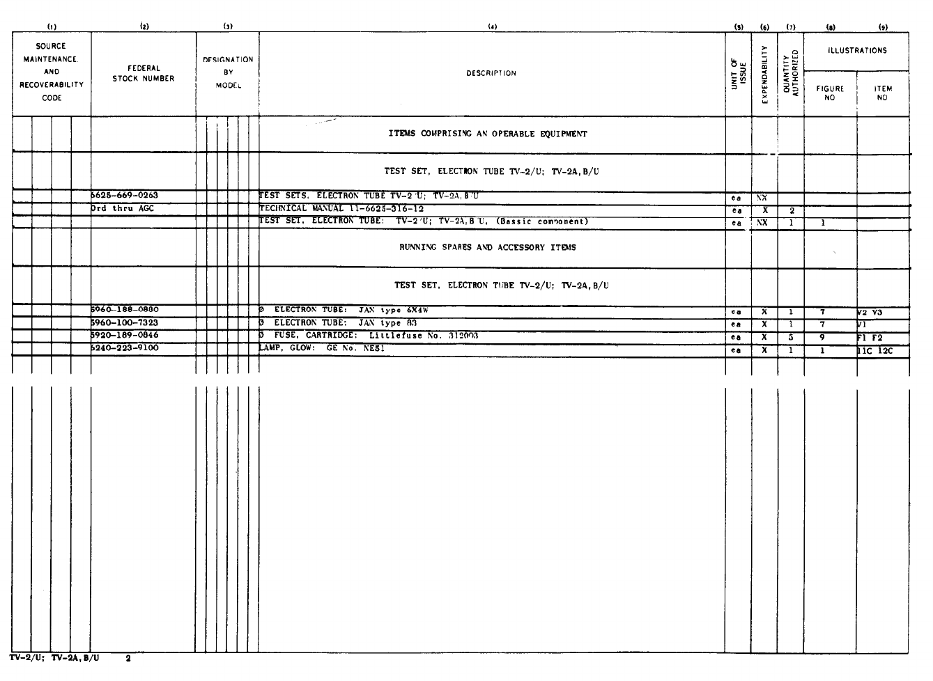
2
PIN :017099-000
