U tec Group UL1 Ultraloq Smart Lock User Manual ul1 user manual V1 1 1 1
U-tec Group Inc. Ultraloq Smart Lock ul1 user manual V1 1 1 1
user manual
Installation Video
Notes
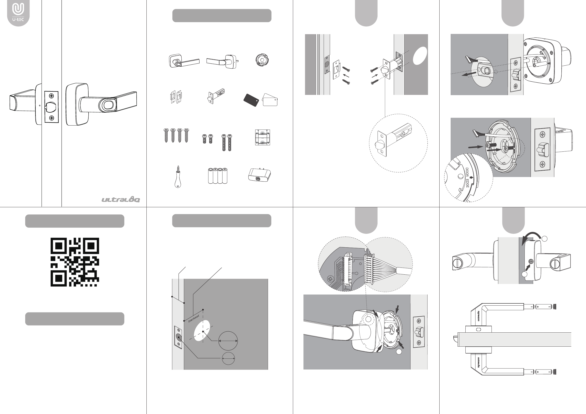
Preparing Door
What’s in the Box
- 2 -
https://www.u-tec.com/installation/ul1
Scan QR code to watch the installation video guide
· Install and test the lock with door open to avoid being
locked out.
· Please follow the instruction in order.
· Need Help? Please contact customer support before
returning the product.
· Visit www.u-tec.com/support
· Email support@u-tec.com
- 3 -
Please check the door’s dimensions.
- 4 -
1. Insert Latch and Strike.
Please align thte Latch
with the door’s edge.
2. Tighten 2 Screw A on
each side to fix the
position.
- 5 - - 6 -
1. Install External Assembly. Align its two sticks with two
holes on the latch.
- 7 -
2. Install Internal Motunting Plate.
Tighten 2 Screw B to fix the position.
1. On Internal Assembly, connect the wire to the receiver. Insert
the spindle into the hole.
2. Match and connect the gaps on Internal Mounting Plate and
Internal Assembly.
Touch the fingerprint sensor to activate it. LED will blink blue.
At this stage, any fingerprint will open the lock.
Please go to the User Guide to set up the lock function.
- 8 -
3. Insert two batteries into each handle.
2 3
/
4 ”
2 3
/
8 ”
(70 mm)
OR
(60 mm)
(33 mm-50mm)
13
/
8
” t
~
1” (25 mm)
2 1
/
8 ”(53 mm)
1”
25 mm
53 mm
2 1
/
8 ”
1. Turn Internal Assembly to the horizonal level.
2. Tighten the screw.
Admin
35~42mm 42~50mm
User
Internal
Assembly
External
Assembly
Internal Assembly
Mounting Plate
Screwdriver Battery Bridge
May not be included for some regions 0ptional
Key Fob
Screw A Screw B Drill Template
Strike Latch
Ultraloq UL1
Smart Lock
Installation Guide
(V1.0)
1
STEP
3
STEP
4
STEP
2
STEP
1
3
/
4
”
(44 mm)
1
3
/
8
”
(35 mm)
1
3
/
4
”
(44 mm)
1
3
/
8
”
(35 mm)
Φ
1” (
25 mm)
Φ
1” (
25 mm)
1
3
/
4
”
(44 mm)
1
3
/
8
”
(35 mm)
Φ
1” (
25 mm)
Centerline
Backset
2
3
/
4
”
(70 mm)
2
3
/
8
”
(60 mm)
Drill Template
(V1.0)
(V1.0)
Plantilla de Perforación
Face of the door
Cara de la puerta
Eje
Fold
Doblar
Fold
Doblar
Entrada de
la cerradura
1
3
/
4
”
(44 mm)
1
3
/
8
”
(35 mm)
Backset
2
3
/
8
”
(60 mm)
Entrada de
la cerradura
2
3
/
4
”
(70 mm)
Centerline
Backset
2
3
/
4
”
(70 mm)
2
3
/
8
”
(60 mm)
5
1
/
2
”
(140 mm)
Face of the door
Cara de la puerta
Face of the door
Cara de la puerta
Face of the door
Cara de la puerta
Edge of the door
Borde de la puerta
Eje
Entrada de
la cerradura
Edge of the door
Borde de la puerta
Backset
2
3
/
8
”
(60 mm)
Entrada de
la cerradura
2
3
/
4
”
(70 mm)
Deadbolt
Latch
5
1
/
2
”
(140 mm)
Φ
2
1
/
8
” (
54 mm)
Φ
2
1
/
8
” (
54 mm)
Φ
1” (
25 mm)
For Door Thickness
Adjust the latch
basket length
Angle faces jamb
Screw A
2 3
/
4 ”
2 3
/
8 ”
(70 mm)
(60 mm)
1
2
1
2
Perform Better Fingerprint FAQ
Use UL1 without Smartphone
- 2 -
1.
Reset UL1 and Register Admin Key.
1) Pin the reset button for 3 seconds. LED will blink blue
seconds.
2) Tap the Black Key Fob (Admin Key) on reader. LED will
flash green.
3) Tap the Black Key Fob again. LED will flash green.
4) Now the Black Key Fob has been registered as the
Admin Key.
2. Enter Register Mode.
1) Tap the Admin Key. UL1 will enter register mode. LED
will blink blue.
2) Now you can register new users by fingerprint or key
fob.
- 5 -
3.
Register a Fingerprint User.
1) Press the finger on the sensor. LED will flash green.
Repeat the process for 3 times.
2) Once the fingerprint has been succussfully registered,
LED will blink blue as waiting for the next action.
Register a Key Fob User.
1) Pick a regular key fob as the User Key.
2) Tap it on the reader. LED will flash green. Repeat the
process for 2 times.
3) Once the key fob has been succussfully registered,
LED will blink blue as waiting for the next action.
4. Exit Register Mode.
When LED is blinking blue, tap the Admin Key or wait 10
seconds to exit the register mode. LED will turn off.
Notes:
1) Whenever LED flash red, it means a failure has
occured.
2) If a failure has occurred, the current process will
be reset. Start over the process.
3) UL1 can store 99 fingerprints & 99 key fobs.
- 6 -
- 3 - - 4 - - 7 -
1. What type of door does UL1 compatible with?
UL1 is a latch lock that compatible with most of American doors
(thickness 33-50mm). Please refer to Page 4 on Installation Guide
for details.
UL1 cannot be installed on glass doors.
2. Does UL1 support left-handed/right-handed opening?
Yes. When installing UL1, adjust its direction to your preference.
3. Installtion completed, but there is no power on UL1.
1) Check the direction of the batteries. Positive pole should
towards the latch.
2) On Internal Assembly, Check if the wire is connected to the
receiver correctly.
4. What’s the difference between App Mode and Standalone
Mode?
App Mode:
Use U-tec App (iOS&Android) via Bluetooth to control lock
(including register and use fingerprint access & key fob access,
check activity log, set lock status, clone user information, etc). If
you have a Ultraloq Bridge, you can control lock remotely.
Standalone Mode:
You can register and use fingerprint access & fey fob access
directly on the lock. No smartphone required and lock cannot be
controlled remotely.
- 8 -
Please check www.u-tec.com for specific
warranty details and limitations.
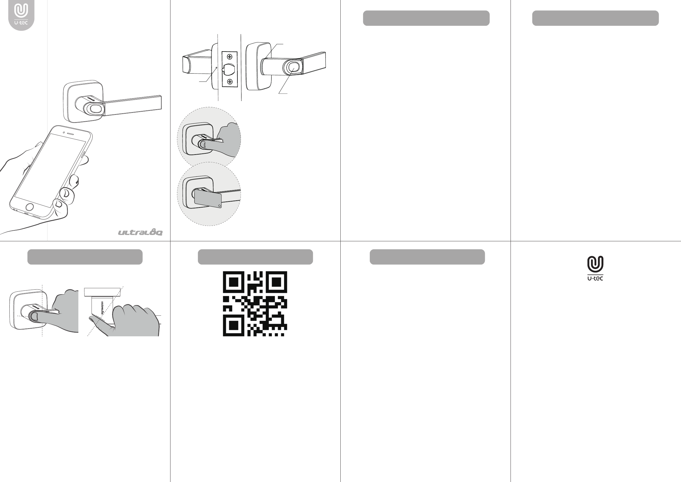
1. Follow the above illustration to register your fingerprint
properly. Make sure your finger is flatly placed at the
center of the reader for a better identification.
2. It is recommended that each user registers two or more
fingerprints. When registering, place your finger at the
center with the same gesture for three times.
3. Please note that dry, wet, oily or dirty fingers may affect
the fingerprint identification.
4. Avoid the callus, peeling or injured finger to ensure the
registration and identification successful.
5. In case of low recognition rate, please delete the original
registered fingerprint and register it again.
Ultraloq UL1
Smart Lock
User Guide
(V1.0)
Warranty Statement
Fingerprint Sensor
Key Fob Reader
Reset
LED Light
Fingerprint Sensor
Key Fob Reader
Use UL1 with Smartphone
1. Scan the QR code to download the U-tec app, or search “U-tec”
in App Store (iOS) and Google Play (Android).
2. Open the app, register U-tec account, and log in the account.
3. Reset UL1, turn on Bluetooth on the phone, stay near the lock,
and search the lock in the app.
4. Add the lock in the app and start to use it.
* UL1 has another independent Standalone Mode that can be
used without smartphone. Please check page 5 and page 6 for
details.
* UL1 has to be reset every time to switch between two
modes. *
* You can only use basic functions in Standalone Mode (Register
and use fingerprint access & key fob access).
Use UL1 without Smartphone
Need Help? Contact Customer Support.
· Visit www.u-tec.com/support
· Email support@u-tec.com

Changes or modifications not expressly approved by the party responsible for
compliance could void the user's authority to operate the equipment。
Note: This equipment has been tested and found to comply with the limits for a Class
B digital device, pursuant to part 15 of the FCC Rules. These limits are designed to
provide reasonable protection against harmful interference in a residential installation.
This equipment generates, uses and can radiate radio frequency energy and, if not
installed and used in accordance with the instructions, may cause harmful interference
to radio communications. However, there is no guarantee that interference will not
occur in a particular installation. If this equipment does cause harmful interference to
radio or television reception, which can be determined by turning the equipment off
and on, the user is encouraged to try to correct the interference by one or more of the
following measures:
—Reorient or relocate the receiving antenna.
—Increase the separation between the equipment and receiver.
—Connect the equipment into an outlet on a circuit different from that to which the
receiver is connected.
—Consult the dealer or an experienced radio/TV technician for help.
FCC ID: ZAJZ2-UL1
U-tec Group Inc.
Model name: Ultraloq Smart Lock
Model No.: UL1
This device complies with Part 15 of the FCC Rules.
Operation is subject to the following two conditions: (1) this
device may not cause harmful interference, and (2) this device
must accept any interference received, including interference
that ma
y
cause undesired o
p
eration.