user manual
EXHIBIT C
User Manual

Installation Guide For UAT ADSL USB Modem
1
ADSL USB NIC User Manual
Revision 1.0
01-10-2001
This document contains confidential information and is
proprietary to UAT Inc.
No part of this document may be reproduced in any form or by any means
without the prior permission of UAT Inc.
All specifications are subject to change without notice.
UAT Inc.
2F, No.5, Alley22, Lane 513, Jui Kuang Rd,
Nei Hu, Taipei
Taiwan, R.O.C
Tel: (886) 2 8797 8488
Fax: (886) 2 2657 0997

Installation Guide For UAT ADSL USB Modem
2
Welcome to ADI USB ADSL Modem!
Introduce yourself to the new world of fast Internet. ADI provides a whole new fast and
simple plug-n-play Universal Serial Bus (USB) Windows environment for Internet access.
The ADI ADSL USB Modem contains a complete evaluation package including hardware
reference design, Windows software drivers, test/utility software, design documents,
performance reports and this user manual.
The manual is written based on the ADI ADSL USB Modem hardware release Version 3.1.3,
the software release Version Alpha01 and the ADIMON GUI Ve rsion 2.5.
The ADI ADSL USB Modem features:
?? Plug and Play USB 1.1 specification interface
?? Rate Adaptive ADSL technology that adapts to your phone line conditions
?? Receive line rate up to 10Mbps (downstream) and transmit line rate up to 1Mbps
(upstream)
System Requirements
To use the USB Modem, your PC or notebook should have:
?? Pentium 233MHz CPU or faster
?? 32MB system memory or more
?? 3MB free space on your hard drive
?? 256 color VGA or higher resolution
?? Microsoft Windows 98 or Windows 98 Second Edition CD-ROM
?? Floppy drive and CD-ROM drive
?? One available USB port and one USB cable
?? RJ11 phone wire
?? DSLAM or central office modem ready
The shielded USB cable is to be used in order to ensure compliance with FCC Part 15,
and it is the responsibility of the user to provide and use shielded USB cable from modem
to personal computer.
CAUTION: Any changes of modifications not expressly approved by the grantee of this
device could void the users authority to operate the equipment.
Document Annotations
Important Instruction
Special Note
Installation Guide For UAT ADSL USB Modem
3
Hardware Installation
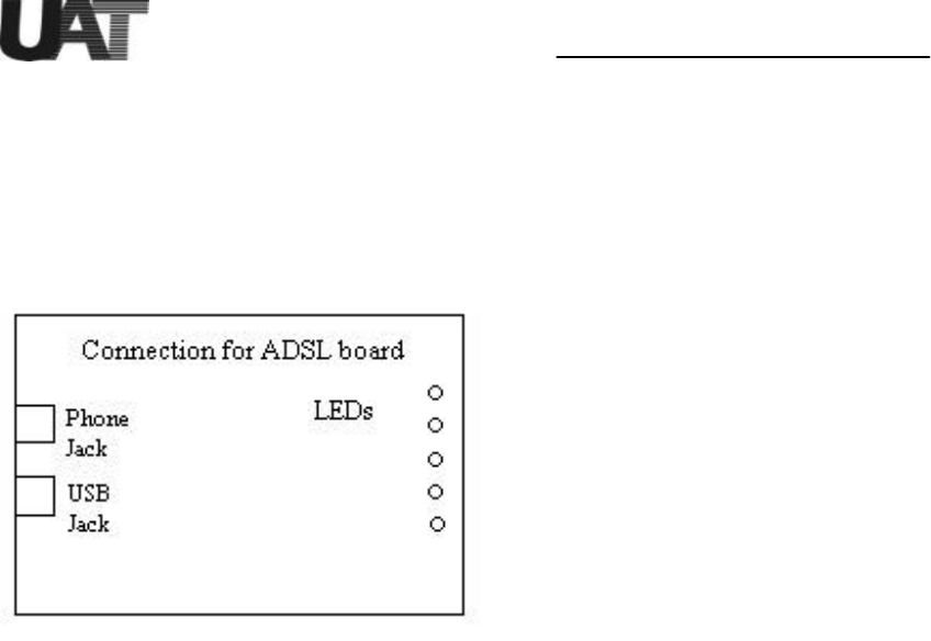
Familiarizing yourself with your USB ADSL Modem
Your modem has one RJ-11 phone jack and USB cable jack receptacle for data connection.
POTS splitters or microfilters can be required to work concurrently with conventional POTS
equipment such as phone, fax and V.90 modem. Various LEDs display modem status.
Installing the ADSL USB modem
To install the modem:
1. Turn on your computer and run Windows 98.
2. Plug USB cable from main computer to modem.
3. Connect your modem using standard phone wire and plug the other side of the wire
to your house phone jack which is connected to central office modem provided by
service provider.
4. Windows USB plug-n-play feature should automatic ally recognize the modem and ask for
software installation.
Installation Guide For UAT ADSL USB Modem
4
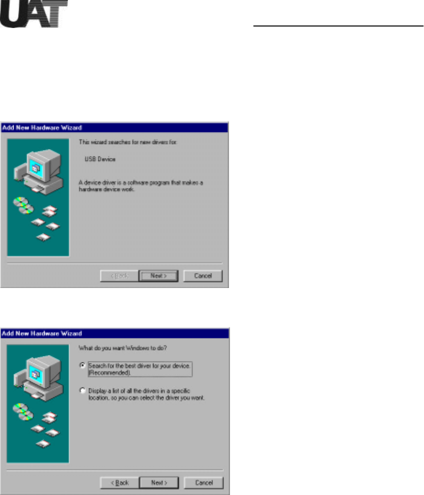
Driver Install
To install the drivers for Windows 98, plug the modem to system using USB cable before
power up the PC or after Windows is running:
1. Windows 98 PnP detects the USB modem USB devices. Click on “Next” from below
screen.
2. Let Windows 98 search for the best driver.
Installation Guide For UAT ADSL USB Modem
5
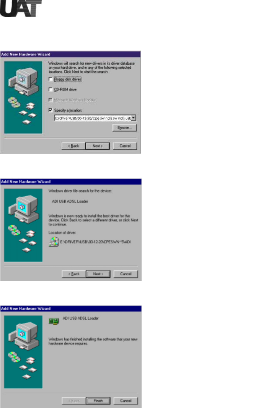
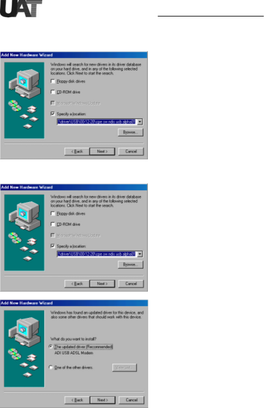
3. Select floppy disk or CD-ROM (recommended) which contain “E:/ driver/USB/00-12-20/
cpe sw ndis sw ndis usb alpha01 for Windows 98 to install the USB firmware loader.
Click on “Next” to continue.
4. Windows 98 detects the ADI USB firmware loader. Click on “Next” to continue.
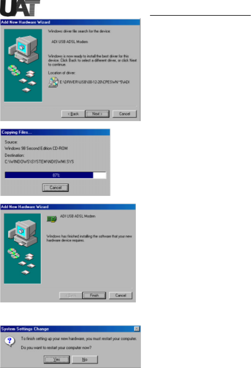
5. Click on “Finish”. ADI firmware is being loaded into the system.
Installation Guide For UAT ADSL USB Modem
6
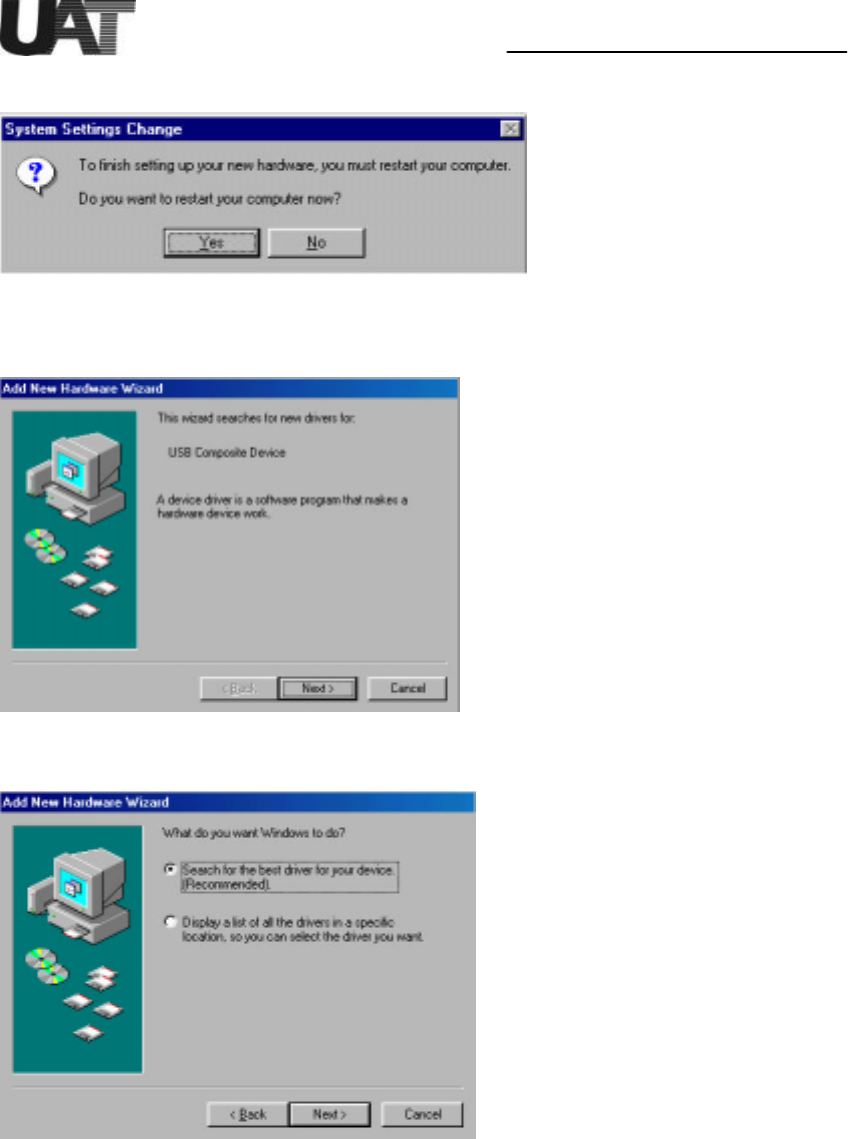
6. Click on “Yes” to re start the PC.
7. Next is to install the ADI USB modem device driver “ADIUSBAE” into the system.
Windows 98 PnP automatically detects the modem and click “Next” to continue.
8. Let Windows 98 search for the proper device driver.
Installation Guide For UAT ADSL USB Modem
7
9. Select floppy disk or CD-ROM(recommended) which contains “ADIUSBAE.SYS” and
“ADIUSBAE.INF” for Windows 98 to install the USB device driver. Click on “Next” to
continue.
10. Follow the installation dialogs to install the driver.
Installation Guide For UAT ADSL USB Modem
8
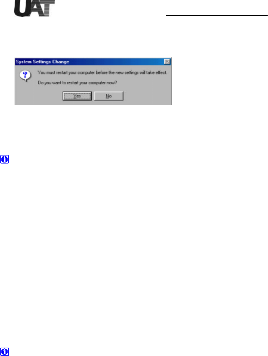
11. Now restart the computer as the system asks.
Note: Unplug the USB cable and do not plug it back until system finishes running
Windows. Otherwise, unexpected crash might be occurred.
Installation Guide For UAT ADSL USB Modem
9
ADIMON USB User Interface GUI Setting Up
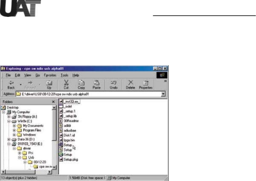
After the PC being restarted, please go to the Start Menu->Program-> Windows
Explorer->[E:]->Driver->USB->00-12-20-> cpe sw ndis usb alpha01, for ADIMON USB
User Interface setting up.
Installation Guide For UAT ADSL USB Modem
10
Changing USB driver parameters
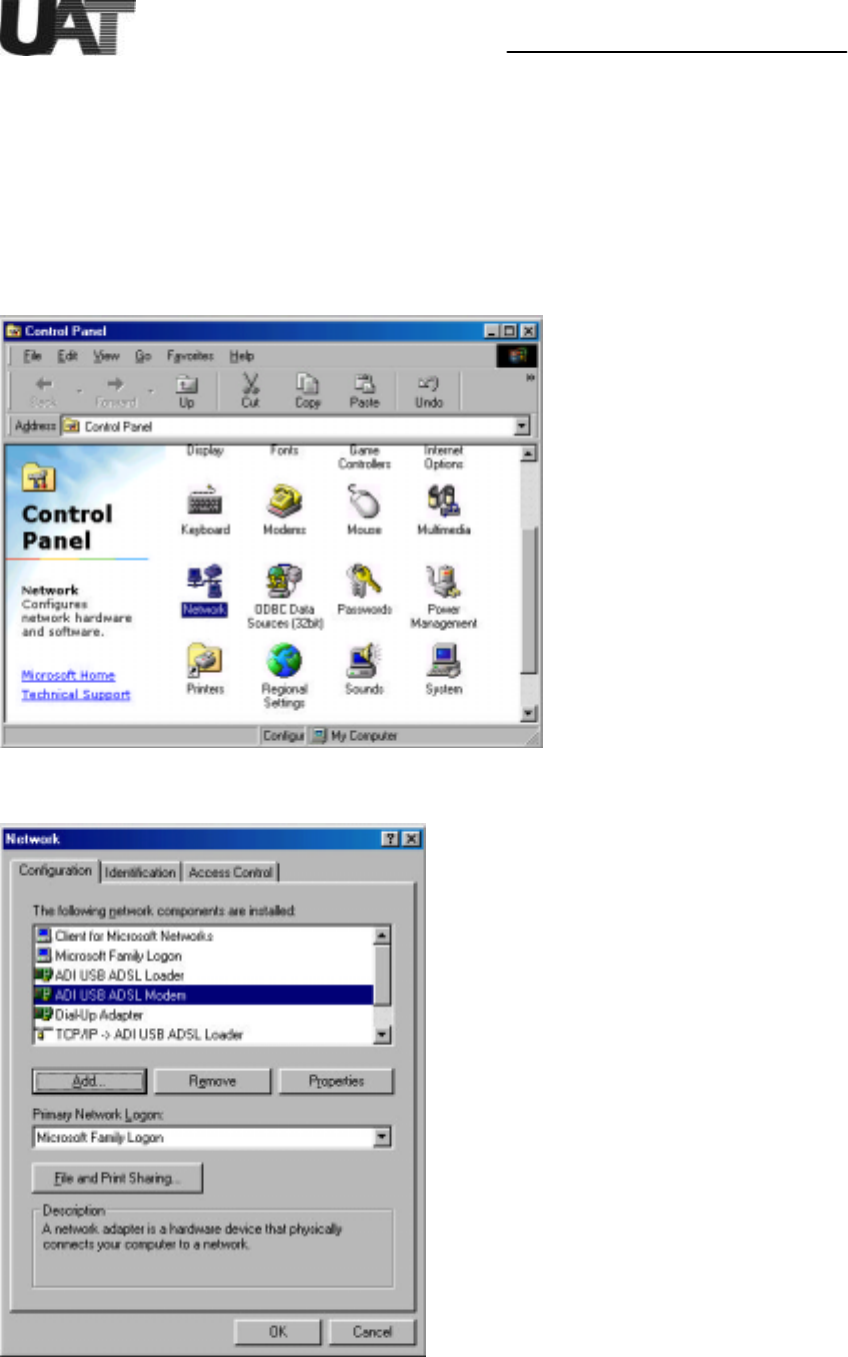
To verify the modem is properly installed, open “Control Panel” and click on “System” icon.
In the “Device Manager” window you should see the “ADI USB ADSL Modem” in the
“Network adapters” list entry. Check USB modem “Properties” to see whether modem is
successfully installed.
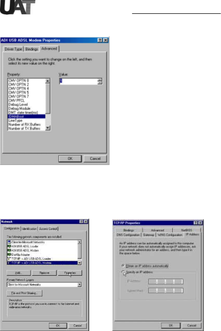
1. Without unplug the USB modem, open “Control Panel” then select “Network” panel.
2. Select “ADI USB ADSL modem” then click on “Properties”.
Installation Guide For UAT ADSL USB Modem
11
3. Click on “Advanced” tab. and change desired driver parameters from the following
windows:
Click on “OK” and back to the Network window to change the TCP/IP Net work Settings.
Changing the TCP/IP Network Settings
Click on the “Network” icon to display the network status. Highlight “TCP/IP ->ADI USB
ADSL Modem” and click on “Properties”.
Obtain all the TCP/IP setup information from your network administrators in order to
configure the TCP/IP protocol. If DHCP server is not available from the CO side, enter
the IP address and subnet mask. Also enter the DNS and Gateway information when
necessary.
Installation Guide For UAT ADSL USB Modem
12
After the IP address being set, please go to Network->ADI USBADSL loader, click on
“Properties” and set the same IP address as in the above procedure.
Now restart the PC again as the system requires.
Modem Parameter Descriptions
CMV OPTN x
Current ADI modem firmware CMV parameter values can be viewed and changed here.
Refer to the ADI ADSL modem software specification for details.
Change LineType greater than 4 to trigger the software driver to pass all the non-default
OPTN values. If LineType is less than 5, driver uses internal OPTN default values
regardless of your new settings. Unless you are familiar with OPTN CMVs, do not change
these parameters.
Debug Level
This entry is used for modem debug and development. It sets different levels of debug
print messages. It can be any combinations of the following values:
0: Minimum messages
1: Errors only
2: Trace only
4: Detail messages only
For example, if you set it to 7 (4+2+1) it prints all debug messages to the debugger.
Default value is set to 10.
Debug Module
Defines the modules need to be debugged. Default is 0xFFFFFFFF which covers all the
modules.
DMT state timer
Time interval to send and receive CMV messages to train the modem in milliseconds.
Default is 200.
IDMA Boot
Modem firmware can be loaded either from the on-board Flash device (default) or from the IDMA interface
(Flashless boot) of the modem. Change value to 1 for IDMA Boot.
In the current software driver release, only Windows 98 Second Edition supports IDMA Boot option.
Line Type
Select default CMV settings for ADSL line types: T1.413, G.DMT or G.LITE.
0: G.LITE
OPTN0 = 0x00900044
OPTN2 = 0x23700000
OPTN4 = 0x321

Installation Guide For UAT ADSL USB Modem
13
PFCL1 = 0x0000000a
1: G.DMT
OPTN0 = 0x00000044
OPTN2 = 0x23700000
OPTN4 = 0x111
2: T1.413
OPTN0 = 0x00000044
OPTN2 = 0x23700000
OPTN4 = 0x2
4: Default setting
OPTN2 = 0x23700000 (only setting)
ADSL firmware is currently defaulted to T1.413.
Number of RX Buffer
Driver receive buffer sizes are 50 (minimum), 1024 (maximum), 50 (default).
Number of TX Buffers
Driver transmit buffer sizes are 50 (minimum), 1024 (maximum), 50 (default).
Retrain
Time interval to receive CMV messages from modem in msec after modem is successfully
trained. This value affects the line re-train response time. Default value is 300.
RFC1483 VCI
Default value is 32. This should match with central office modem value.
RFC1483 VPI
Default value is 0. This should match with central office modem value.
RFC1483Mode
Value 0 indicates Ethernet driver.
Value 2 indicates IP driver.
After changing the desired parameter value(s), click “OK” to close the “Modem Properties”
windows. While the system asks for reboot, either reboot the PC or simply unplug the
USB cable, wait a few seconds and plug back to the modem. New values will then be
loaded into the system.
Installation Guide For UAT ADSL USB Modem
14
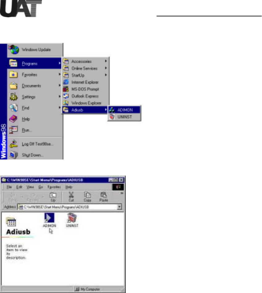
After the ADSL USB modem has been successfully installed. ADIMON GUI can be opened
from Start Menu ->Program->Adiusb. Double click on the “ADIMON’ icon.
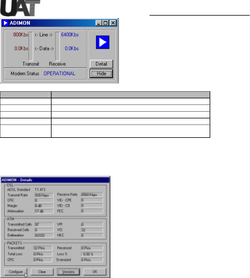
The first screen is the Summary Window, which shows the ADSL modem status including
ADSL line and data rates.
Installation Guide For UAT ADSL USB Modem
15
Information Field Description
Transmit Line Rate Upstream data rate negotiated by the ADSL link (Kbit/s)
Receive Line Rate Downstream data rate negotiated by the ADSL link (Kbit/s)
Transmit Data Rate Actual user data transmit rate (Kbit/s)
Receive Data Rate Actual user data receive rate (Kbit/s)
Modem Status Status of the modem:
(IDLE, OPERATIONAL, INITIALIZING, FAILED)
The Details Window provides detailed information for the ADSL, ATM and Packets
parameters. The information is grouped accordingly to DSL, ATM and PACKETS. The
meanings of each field are listed in the table below.
Installation Guide For UAT ADSL USB Modem
16
DSL Information
Field
Description
ADSL Standard ADSL Standard (ANSI T1.413, G.DMT, G.LITE, Multi-Standard)
Transmit Rate Upstream data rate negotiated by DSL link (Kbit/s)
Receive Rate Downstream data rate negotiated by DSL link (Kbit/s)
CRC Number of errors per second since training
Margin Near end (CPE) current SNR margin (dB)
Attenuation Current attenuation (dB)
VID-CPE Vendor ID of the DSL ATUR
VID-CO Vendor ID of the DSL ATUC
FEC Number of uncorrectable errors since start of link
ATM
Information Field
Description
Transmitted Cells Number of (non-IDLE) ATM cells transmitted since start of link
Received Cells Number of (non-IDLE) ATM cells received since start of link
Delineation ATM delineation status: LOSS or GOOD. GOOD implies that
ATM Sync is achieved and maintained.
VPI Virtual Path Identifier field used in the ATM cell header
VCI Virtual Channel Identifier field used in the ATM cell header
HEC Number of received ATM cells with errors in the ATM cell header
since start of link.
Packet
Information Field
Description
Transmitted Number of AAL5 packets transmitted since start of link
Received Number of AAL5 packets received since start of link
Total Loss Number of AAL5 packets received that are discarded (due to CRC
errors and oversize)
Loss % Percentage of AAL5 packets received that are discarded
CRC Number of A AL5 packets with checksum errors
Oversized Number of oversized packets received
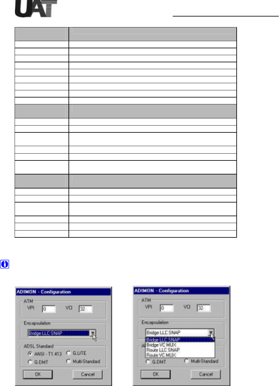
The Configuration Window allows users to change the modem configuration information.
For configuration changes to take effect, the USB modem is required to unplug and plug
back from the USB cable (or simply reboot the PC).
Installation Guide For UAT ADSL USB Modem
17
Information Field Description
ATM The VPI and VCI values can be changed here, the values are to be
entered using decimal format
Encapsulation For the NDIS driver, choices include Bridge LLC SNAP, Bridge VC
MUX, Route LLC SNAP or Route VC MUX. NDISWAN driver
selection will be added in later release version.
ADSL Standard Choices are ANSI T1.413, G.LITE, G.DMT and Multi-Standard
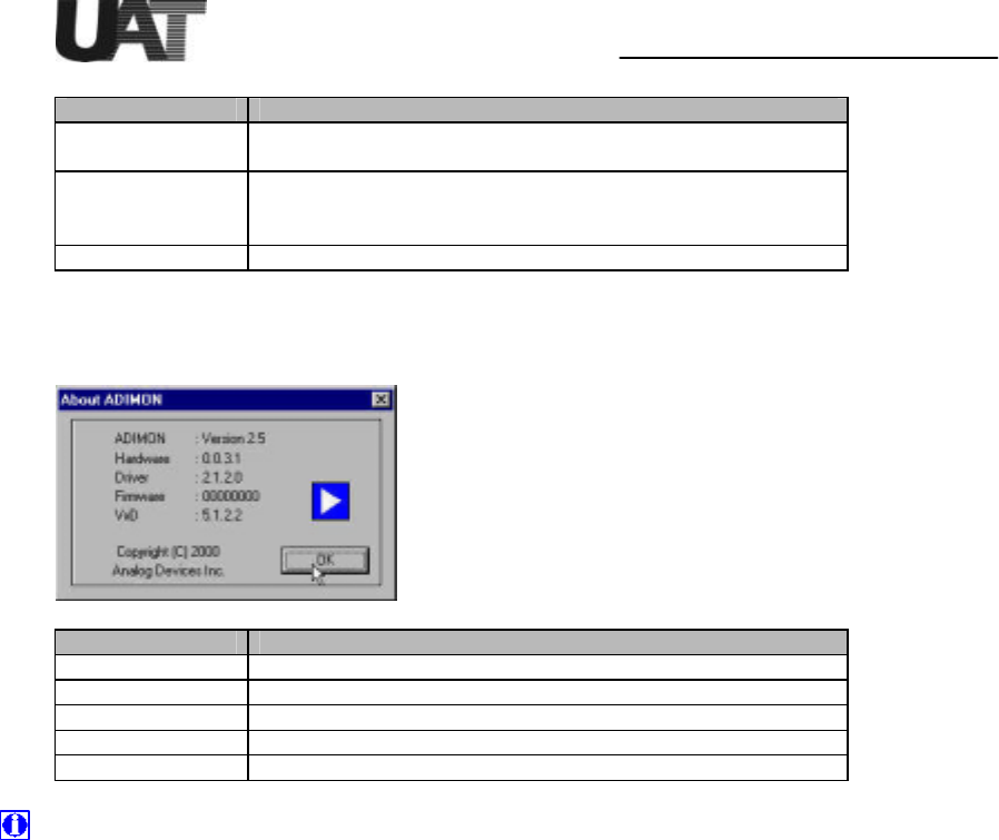
The Version Window can be opened from the Details Windows.
Information Field Description
ADIMON GUI version
Hardware Evaluation board version
Driver Windows device driver version
Firmware DSL modem firmware version
VxD Virtual device driver version
The ADIMON GUI consists of a User Interface (written using MFC and compiled under
Visual C++ 6.0) and a Virtual Device Driver (VxD) that facilitates information sharing
between the USB device driver and the user interface (compiled using Windows 98 DDK).
For product customization, source code is available upon request.

Installation Guide For UAT ADSL USB Modem
18
Uninstall the USB ADSL modem
To uninstall the modem:
1. From Windows Start menu, choose Programs->Adiusb and click on “UNINST”. Click
“ Yes” to confirm file deletion, UNInstallShield will remove the related files
2. From Windows Start menu again, choose Settings->Control Panel and select “Network”
properties. Highlight “ADI USB ADSL Loader” and “ADI USB ADSL Modem” and
remove both entries. Click on “OK” to exit. Restart the PC while system asks.
3. Unplug the USB modem.

Installation Guide For UAT ADSL USB Modem
19
Troubleshooting the Modem
Please read the following Q&A to help debugging the problems with your ADI ADSL USB modem.
USB driver is not re-loaded after unplug and plug back the USB cable to modem.
Check “Device Manager” from “System Properties”, delete unknown USB device(s) if any.
After followed driver installation procedures, modem is still not working.
One obvious way is to check on board LED status. Provided DSLAM is ready for operation, LED D6 should
be “blinking” (default setting) for the central office modem detection. Make sure line type selection matches
with what DSLAM supports.
Which OS works the best?
Both Windows 98 and Windows 98 2nd Edition are supported. Windows 98 2nd Edition supports USB bus
power management and Native ATM functions, therefore it is recommended to use. Most versions of
Windows 95 and Windows NT do not support USB. Windows Millennium and Windows 2000 will be fully
supported in future software releases. Consult your local ADI representatives for release schedules.
How do I know if ADI USB driver is installed correctly?
Open “Network Panel” from “Control Panel” folder. “ADI USB ADSL Modem” entry under the Adapter tab
should exist. Click on its “Properties”, it will show that USB is corr ectly installed or not. Also select
“Device Manager” menu from “System” properties of “Control Panel” to check the existence of USB driver
from “Network adapters”.
Is my modem trained correctly?
LED D6 should remain “ON” when the modem is correctly linke d to the central office modem. The blinking
rate of LED D9 indicates how frequent CRC errors occur in the ADSL modem. Excessive CRCs will cause
rate reduction in data flow.
Is the line passing data?
To determine if data flow is occurring, execute the program “Netstat.exe” (e.g. “netstat –e” to view Ethernet
statistics) from a DOS Window. If data flow is occurring, the values given by Netstat should be increasing
every time it is executed.
How do I set modem IP address?
To determine the modem IP address, execute the program “ipconfig.exe” (e.g. “ipconfig /all”) from a DOS
Window. The IP address is shown on the line “IP Address”. For example: IP Address . . . . . . . . . : 196.168.0.2
Consult your network administrator or service provider to determine if it is valid or not. IP address is set in
“Network Panel” from “Control Panel” folder. Double click on “TCP/IP ->ADI USB ADSL Modem” to
change IP address.
Can’t install the device driver?
If you have installed previous release versions of device driver, ext ra uninstall steps are required:
- Remove "ADI USB ADSL Modem" and "ADI USB ADSL Loader" from Control Panel->Network
Properties.
- Search and delete *ADIUSB*.*, *ADILOAD*.* and *ADILDR*.* files under all the
subdirectories of Windows (such as C:\Windows). Then unplug and plug back the USB
modem, remove "ADI Modem Firmware" from System Properties->Device Manager.
- Reboot PC before new driver installation.

Installation Guide For UAT ADSL USB Modem
20
Copyright & Regulatory Information
This manual and software described in it are copyrighted with all rights reserved. This
manual may not be copied, in whole or in part, without written consent. All product names
are trademarks and or registered trademarks of their respective companies.
FCC Statement
This equipment has been tested and found to comply with the limits for a Class B digital
device, pursuant to Part 15 of the FCC Rules. These limits are designed to provide
reasonable protection against harmful interference in a residential installation. This
equipment generates, uses and can radiate radio frequency energy and, if not installed and
used in accordance with the instructions, may cause harmful interference to radio
communications. However, there is no guarantee that interference will not occur in a
particular installation. If this equipment does cause harmful interference to radio or
television reception, which can be determined by turning the equipment off and on, the user
is encouraged to try to correct the interference by one or more of the following measure:
!!Reorient or relocated the receiving antenna.
!!Increase the separation between the equipment and receiver.
!!Connect the equipment into a different outlet circuit from than the receiver.
!!Consult an experienced radio/TV technician for help.
The shielded USB cable is to be used in order to ensure compliance with FCC Part 15,
and it is the responsibility of the user to provide and use shielded USB cable from modem
to personal computer.
CAUTION: Any changes of modifications not expressly approved by the grantee of this
device could void the users authority to operate the equipment.