User Manual
Quick Start
ADSL Modm Card
Table of Contents
Congratulations!................................................................................................................1
Step 1 – Know your PC’s Operating System...............................................................1
Step 2 – Determine your Connection Settings ...........................................................2
Step 3 – Install the ADSL Modem Card.......................................................................3
Step 4 – Install the Drivers and Make a Connection .................................................5
Windows 95A ....................................................................................................................6
Windows 95B.....................................................................................................................8
Windows 98, 98SE...........................................................................................................11
Setting the ADSL Configuration...........................................................................13
Making a RFC 1483 or RFC 1577 connection - 95A, 95B, 98, 98SE .................14
Making a RFC 2364 connection - 95A, 95B, 98, 98SE........................................18
Windows 2000 .................................................................................................................19
Setting the ADSL Configuration...........................................................................21
Making a RFC 1483 or RFC 1577 connection - 2000 ..........................................22
Making a RFC 2364 connection - 2000.................................................................24
Windows NT4.0 - RFC 1483 or RFC 1577 ....................................................................25
Setting the ADSL Configuration for RFC 1483 or RFC 1577.............................27
Windows NT4.0 - RFC 2364...........................................................................................28
Setting the ADSL Configuration for RFC 2364...................................................31
Creating a Dial-up Network Connection......................................................................32
Appendix
Editing your Service Connection..................................................................................33
Removing Drivers............................................................................................................34
Diagnostic Tools .............................................................................................................35
Trouble Shooting ............................................................................................................37
Connector Pin-out ...........................................................................................................38
LED Functions.................................................................................................................38
System Requirements & Compliance information......................................................39
Copyright & Regulatory Information...........................................................................39
1
Congratulations!
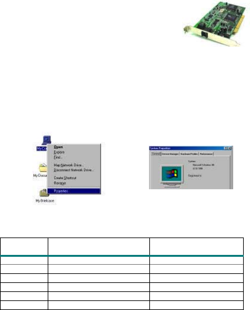
You are about to accelerate into ADSL technology. Your new ADSL modem card is an
internal Asymmetric Digital Subscriber Line (ADSL) PCI modem card, which
conveniently plugs into your computer system. The
modem connects directly to your telephone line via a
standard connector.
This guide is designed to walk you through installation of
your ADSL Modem card in the easiest and quickest way
possible. Please follow the instructions carefully.
Step 1 – Know your PC’s Operating System
You will need to know the exact version of Microsoft Windows installed in your
computer. If you do not know or are unsure, please proceed as follows to determine your
version of the Microsoft Operating System.
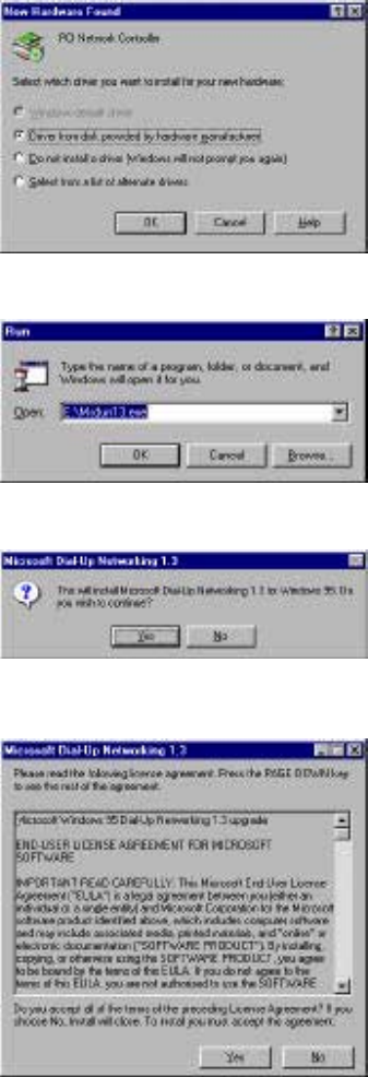
On your desktop, right-click My Computer. Then select Properties. The version
number of the Microsoft Windows Operating System installed in your computer will be
displayed on the General tab. Refer to the following table for more detailed information.
Windows OS System Properties Description Release (Microsoft Web)
W
i
n 95A
4 00 950A
Windows 95 OSR1
Win 95B 4.00.950B
Windows 95 OSR2
Win 98 4.10.1998 Window 98
Win 98SE
4.10.2222A 2nd Edition
Windows 98 2nd Edition
Win 2000 5.00.2195 Windows 2000
Win NT 4.00.1381 Windows NT 4.0
If you have questions regarding your PC system and the Microsoft Windows Operating
System, please contact your original PC manufacturer or Microsoft for assistance.
Before Installing the ADSL PCI Modem Card, it is important to verify that the ADSL data
port RJ-11 jack is configured so that the center two pins, pins 3 and 4, are used for ADSL
data, otherwise the ADSL PCI modem card will not make a proper connection. If the ADSL
2
data port installation uses pins 2 and 5 for data, then a wiring converter will be required. Do
not alter or remove a wiring converter if present. Consult with your ADSL service provider
regarding a wiring converter or before attempting any wiring changes.

3
Step 2 – Determine your Connection settings
You need to know your PC systems Windows OS and Internet Protocol supplied by
your ADSL service provider. Refer to the following chart for your ADSL Driver.
Protocol Selection
RFC1483 !!Bridged Ethernet over ATM
RFC2364 !!Point-to-Point Protocol over ATM
RFC1577 !!Classical Internet Protocol over ATM
RFC2516 !!Point-to-Point Protocol over Ethernet
ADSL Driver
Selection
RFC1483 RFC2364 RFC1577 RFC2516
Win 95A & 95B 1483w95 2364w95 1577w95 See Note!
Win 98 & 98SE 1483w98 2364w98 1577w98 See Note!
Win NT 4.0 1483nt4 2364nt4 1577nt4 See Note!
Win 2000 1483w2k 2364w2k 1577w2k See Note!
Note! : RFC2516 (Point-to-Point Protocol over Ethernet) is supported by third
party developers. See the PPPoE driver supplement for detailed information and
installation instructions.
Having determined the ADSL Driver you will be installing, you now need to gather the
connection information supplied by your ADSL service provider.
VPI value:_________
VCI value:_________
Framing: ! VC/MUX ! LLC/SNAP
Mode: ! ANSI T1.413 ! ITU G.lite ! ITU G.dmt
For RFC 1483 or 2516 For RFC 2364 or 1577
Host: User Name:
Domain: Password:
Gateway: Host or IP Address:
IP Address:
Subnet Mask:
DNS or server address:
4
Step 3 – Install the ADSL modem card
Caution: To avoid possible damage to your modem card, touch the metal chassis of your
PC system to remove static charge from your person, and then remove your ADSL
modem card from the protective anti-static bag.
1. Shut down your computer and switch the power off.
2. Unplug the power cord for your computer from the electrical outlet.
3. Remove the cover from your systems chassis (see your PC manufacturer’s manual).
4. Unscrew “slot cover bracket” from an unused PCI (usually white in color) slot.
5. Gently and evenly insert the PCI modem card into your empty PCI slot.
6. Make sure the card is firmly seated, and then secure the card with the bracket
screw.
7. Replace the cover of your computer system.
8. Connect the ADSL/phone line to the connector port on the modem card and
plug the other end of the cable into your ADSL/phone service.
5
Step 4 – Install the drivers and make a connection
You will be installing drivers and then proceeding to make an Internet connection. This
process requires you to enter in information as prompted by the Microsoft Installation
Wizard.
NOTE: You may need the Microsoft Windows Operating System installation files (CAB
files) to complete the installation. The CAB files are contained in the Microsoft’s system
CD-ROM. Some systems may have already installed the CAB files to the hard drive, but
you should have the Microsoft Windows CD-ROM handy just in case.
Proceed now to the installation procedure for the Windows Operating System
installed in your computer.
Windows 95A -------------------------------------------------------------------------------Page 6
Windows 95B -------------------------------------------------------------------------------Page 8
Windows 98, 98SE------------------------------------------------------------------------- Page 11
Windows 2000 ------------------------------------------------------------------------------Page 19
Windows NT - RFC 1483 or RFC 1577 -----------------------------------------------Page 25
Windows NT - RFC 2364----------------- -----------------------------------------------Page 28
6
Windows 95A
After installing the ADSL modem card, plug the power cable back into the PC system and
turn the power on.
Before you proceed to install drivers you will need to upgrade your Dial-Up
Networking (DUN) application to version 1.3 or above. The Microsoft DUN is
conveniently contained on your ADSL Driver CD-ROM.
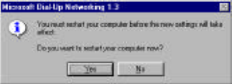
1. After restart, the Update Device Driver
Wizard will detect the ADSL modem as a
PCI Network Controller. CANCEL the
New hardware found window.
2. At your desktop, click Start, and then
select Run.
3. The Run window appears. Insert the
ADSL Driver CD, then click on Browse
and proceed to locate the ADSL Driver 95
CD-ROM. Then locate and select the
Msdun13.exe file. The Msdun13.exe
appears in the Open box. Click OK.
4. The Microsoft Dial-Up Networking 1.3
window appears with the message This
will install Microsoft Dial-Up
Networking 1.3 for Windows 95. Do
you wish to continue? Click Yes.
5. An End-User License Agreement will
appear. To accept, click Yes.
7
6. Back in the Microsoft Dial-Up
Networking 1.3 window. You will be
asked: Do you want to restart your
computer now? Click Yes.

8
NOTE: You may need the Microsoft Windows Operating System installation files (CAB
files) to complete the installation. The CAB files are contained in the Microsoft’s system
CD-ROM. Some systems may have already installed the CAB files to the hard drive, but
you should have the CD-ROM handy just in case.
7. After your computer reboots, the New
Hardware Found window will detect the
ADSL modem card as a PCI Network
Controller. Select the Driver from disk
provided by hardware manufacturer
option. Click OK.
8. Insert the ADSL Driver CD-ROM into
your systems CD drive.
9. The Install From Disk window appears.
Click Browse to locate the driver on your
CD-ROM for the protocol supported by
your ADSL provider: 1483w95,
2364w95, or 1577w95 (The example uses
“D” as the CD-ROM drive letter. Drive
letters may vary.) Then click OK.
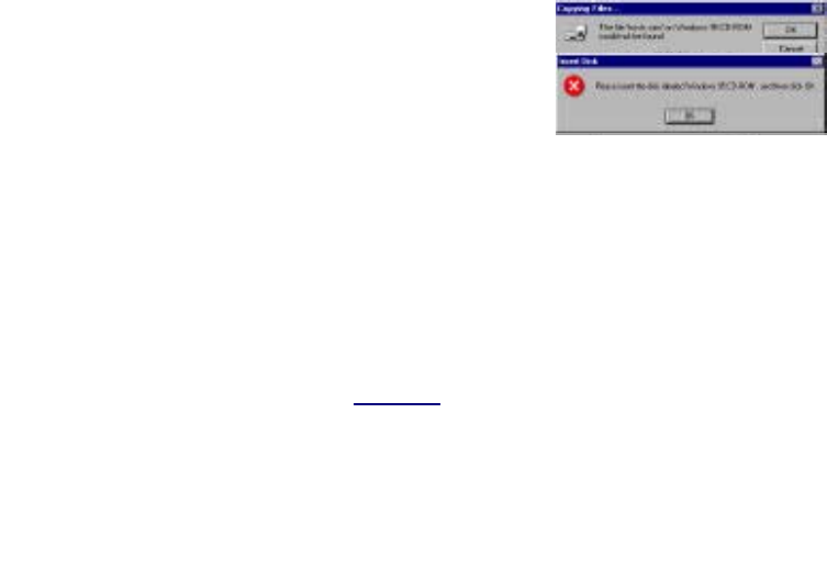
NOTE: During the installation process
you may be asked to insert your
Windows 95 CD. Insert the Windows 95
CD into the CD drive and click OK.
NOTE: If during the file copying process
a file is reported as “not found” enter the
path with the CD Drive letter
and :\Win95 (ex:D:/Win95).
10. You must now set the ADSL configuration. Go to page 13.
9
Windows 95B
After installing the ADSL modem card, plug the power cable back into the PC system and
turn the power on.
Before you proceed to install drivers you will need to upgrade your Dial-Up Networking
(DUN) application to version 1.3 or above. The Microsoft DUN is conveniently
contained on your ADSL Driver CD-ROM.
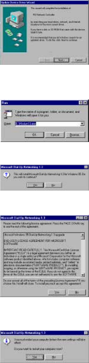
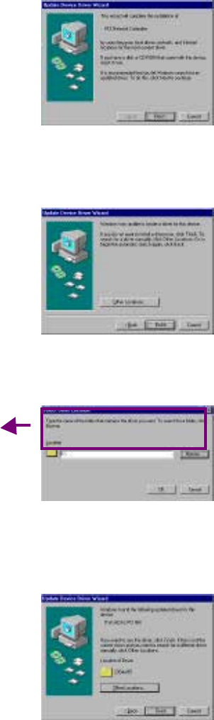
1. After restart, the Update Device Driver
Wizard will detect the ADSL modem
card as a PCI Network Controller.
CANCEL the New hardware found
window.
2. At your desktop, click Start, and then
select Run.
3. The Run window appears. Insert the
ADSL Driver CD, then click on Browse
and proceed to locate the ADSL Driver 95
CD-ROM. Then locate and select the
Msdun13.exe file. The Msdun13.exe
appears in the Open box. Click OK.
4. The Microsoft Dial-Up Networking 1.3
window appears with the message This
will install Microsoft Dial-Up
Networking 1.3 for Windows 95. Do
you wish to continue? Click Yes.
5. An End-User License Agreement will
appear. To accept, click Yes.
6. Back in the Microsoft Dial-Up
10
Networking 1.3 window. You will be asked Do you want to restart your
computer now? Click Yes.
You may need the Microsoft Windows Operating System installation files (CAB files) to
complete the installation. The CAB files are contained in the Microsoft’s system CD -
ROM. Some systems may have already installed the CAB files to the hard drive, but you
should have the CD-ROM handy just in case.
7. After your computer reboots, the Update
Device Driver Wizard will detect the
ADSL modem card as a PCI Network
Controller, click Next.
8. Insert the ADSL Driver CD-ROM into
you systems CD drive.
9. The Update Device Driver Wizard will
appear and indicate that “Windows was
unable to locate a driver for this
device”. Click Other Locations.
10. The Select Other Location window
appears. Click Browse to locate the driver
on your CD-ROM for the protocol
supported by your ADSL provider:
1483w95, 2364w95 or 1577w95
(The example uses “E” as the CD -ROM
drive letter. Your drive may have a
different letter.) Then click OK.
11. The Update Device Driver Wizard will
then find the ITeX ADSL PCI NIC. Click
Finish.
11
NOTE: During the installation process
you may be asked to insert your Windows
95 CD-ROM. Insert the Windows 95 CD
into the drive and click OK.
NOTE: During the installation process
you may be asked to insert your
Windows 95 CD-ROM. Insert the Win95
CD into the drive. Click OK.
NOTE: If during the file copying process
a file is reported as “not found” enter the
path (CD Drive letter) and :\Win95 (ex.
D:\Win95)
12. You must now set the ADSL configuration. Go to page 13.

12
Windows 98, 98SE
After installing the ADSL modem card, plug the power cable back into the PC system and
turn the power on.
1. The Add New Hardware Wizard window
will automatically appear to indicate that a
new PCI Network Controller has been
found. Click Next.
2. Still in the Add New Hardware Wi zard.
You will be asked “What do you want
Windows to do?” Select the Search for
the best driver for your device option,
then click Next.
3. Insert the ADSL Driver CD into your
systems CD-ROM drive.
4. Select Specify a location and click
Browse to locate the driver on your CD-
ROM for the protocol supported by your
ADSL provider: 1483w98 or 2364w98 or
1577w98 (The example uses “D” as the
CD-ROM drive letter. Your drive may
have a different letter.) Then click Next.
5. The Add New Hardware Wizard will
appear and indicate the ITeX ADSL PCI
NIC has been recognized and will install a
new driver. Click Next.
13
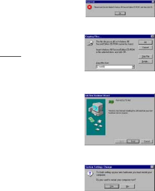
6. If prompted to insert your Windows
CD, do so at this time, then click OK.
7. Enter the [CD drive Letter] and
then :\Win98 (e.g: E:\Win98) and
click OK.
8. At the conclusion of the ADSL
modem driver installation, the Add
New Hardware Wizard window
appears and displays your newly
installed ITeX ADSL PCI NIC.
Click Finish.
9. The System Settings Change
window appears. For the PC system
to set up the ITeX Apollo 2 Drivers,
a system Restart is required. Click
Yes.
NOTE: After restarting the system, the Diagnostic Tool icon (See Appendix) is active
and monitoring connectivity.
10. You must now set the ADSL configuration. Go to page 13.
14
NOTE: THE SERVICE MODE TYPE
WILL BE ONE OF THE FOLLOWING:
!!ANSI T1.413 Issue 2
!!ITU G.992.2 Annex A (G.lite)
!!ITU G.992.1 Annex A (G.dm
SETTING THE ADSL CONFIGURATION
FOR RFC 1483/1577/2364
WINDOWS 95/98
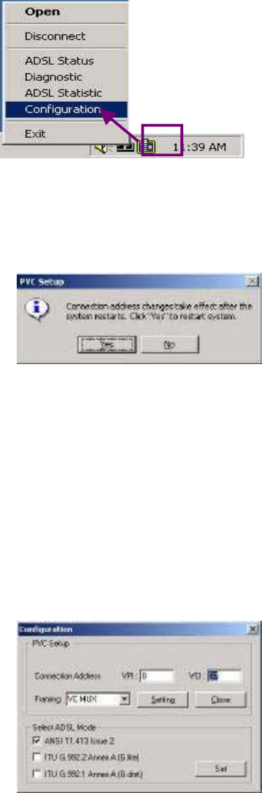
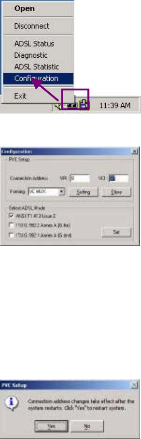
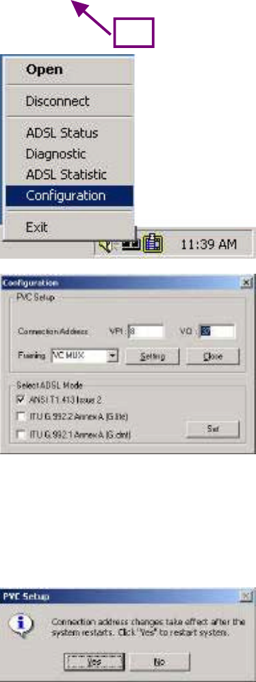
1. After your PC has rebooted, right-click
on the Mapi Icon, and select the
Configuration option.
2. The Configuration window appears.
This is the Network Protocol and
PVC settings section. Enter in the
VPI, VCI, and Framing values
supplied by your ADSL service
provider.
3. In the Select ADSL Mode section,
select the mode(s) recommended by
your ADSL service provider. Click on
the mode(s) required and then click on
4. The PVC Setup window appears.
Click Yes to restart your PC system
and to allow the new changes to take
effect.
5. You must now make an ADSL connection.
Proceed to the section for your protocol.

15
Making an ADSL connection
RFC 1483 – Bridged Ethernet over ATM – 95/98
RFC 1577 - Classical Internet Protocol over ATM – 95/98
1. From the Start menu on the tool bar,
select Settings, Control Panel, and
then double-click on the Network icon.
2. The Network window appears. Select
the Configuration tab, scroll the
installed network component window
an
df
in
d
ITeX
AD
SL PCI NIC
.
RFC1483 Bridged Ethernet over ATM !! Go to page 14
RFC1577 Classical Internet Protocol over ATM !! Go to page 14
RFC2364 Point-to-Point Protocol over ATM !! Go to page 18

16
3. Scroll the installed network component
window and select TCP/IP !ITeX
ADSL PCI NIC. Then click the
Properties button.
4. The TCP/IP Properties window will
appear. Select the IP Address tab and
then select the Specify an IP Address
option. Enter the IP Address and
Subnet Mask settings supplied by your
ADSL
p
r
ov
i
de
r
.
17
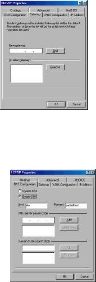
5. To setup a new gateway, select the
Gateway tab, and then enter the setting
in the New Gateway section. Click Add.
6. Select DNS Configuration tab. Select
the Enable DNS option.
NOTE: You now need to have available
the Host, Domain and DNS settings
supplied by your ADSL service
prov
i
der
7. Enter your host name into Host: box.
8. Enter your domain name into Domain:
box.
9. Enter DNS number into DNS Server
Search Order box and click Add. If
you have more than one DNS numbers,
repeat this step.
10. After setting all the necessary TCP/IP
p
ro
p
erties, click OK.

18
11. The Network window appears. Click
OK.
12. The System Setting Change window
appears. You will be asked if you want
to restart your computer. Click Yes.
Congratulations, you are done. Your ADSL Internet connection is established!

19
2. The Connect To window appears.
Enter the User Name and Password
supplied by your Internet service
provider (ISP). Then click Connect.
3. The Connecting to My Connection
window appears. The message
Logging on to network confirms a
valid connecting process.
4. The Connection Established
window appears. Internet service is
now established. Click Close and
then the Diagnostic tool icon will
appear on the task bar.
Congratulations, you are done. Your ADSL Internet connection is established!
Making an ADSL connection
RFC 2364 - Point-to-Point Protocol over ATM – 95/98
1. Double-click on the ITeX
PPPoA icon that appears on
your desktop.
20
Windows 2000
After installing the ADSL modem card, plug the power cable back into the PC
system and turn the power on.
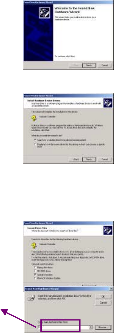
1. After installing the ADSL modem card,
power on the PC system. After start-up,
the Found New Hardware Wizard will
appear. Click Next.
2. Still in the Found New Hardware
Wizard,
select the Search for a suitable device.
option. Click Next.
3. Next you will be prompted for software
drivers. Select Specify a location. Click
Next.
4. Insert the ADSL Driver CD into the
systems CD-ROM drive. Click Browse to
locate the driver on your CD-ROM for
the protocol supported by your ADSL
provider: 1483w2K or 2364w2K or
1577w2K (The example uses “D” as the

21
CD-ROM drive letter. Your drive may
have a different letter.) Click OK.
5. The Found New Hardware Wizard will
then find the ITeX ADSL PCI NIC, click
Next.
6. The Digital Signature Not Found
window
appears. You will be asked; Do you want
to continue installation? Click Yes.
7. The Found New Hardware Wizard will
prompt that Windows has finished
installing the software for this device.
Click Finish.
NOTE: You may be asked if you want to restart your computer, if so click Yes. If
you are not asked, you need to restart your computer manually at this time.
8. You must now set the ADSL configuration. Go to page 21.
22
NOTE: The service mode type will be one of
the following:
!!ANSI T1.413 Issue 2
!!ITU G.992.2 Annex A (G.lite)
!!ITU G.992.1 Annex A (G.dmt)
.
RFC1483 Bridged Ethernet over ATM !! Go to page 22
RFC1577 Classical Internet Protocol over ATM !! Go to page 22
RFC2364 Point-to-Point Protocol over ATM !! Go to page 24
SETTING THE ADSL CONFIGURATION
FOR RFC 1483/1577/2364
WINDOWS 2000
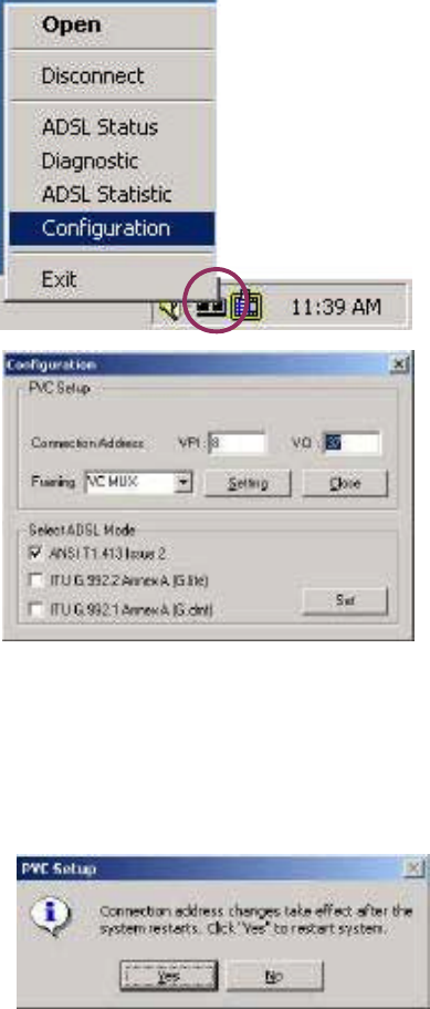
1. After your PC has rebooted, right-click
on the Mapi Icon, and select the
Configuration option.
2. The Configuration window appears.
This is the Network Protocol and
PVC settings section. Enter in the
VPI, VCI, and Framing values
supplied by your ADSL service
provider.
3. In the Select ADSL Mode section,
select the mode(s) recommended by
your ADSL service provider. Click on
the mode(s) required and then click on
4. The PVC Setup window appears.
Click Yes to restart your PC system
and to allow the new changes to take
effect.
5. You must now make an ADSL connection. Proceed to the section for your protocol.
23
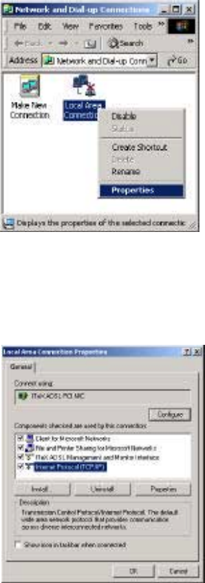
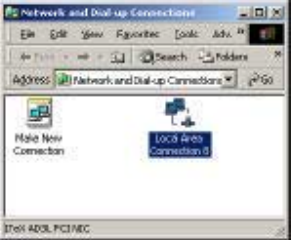
3. The Local Area Connection window
appears. Click on Internet Protocol
(TCP/IP), then click on Properties.
Making an ADSL connection
RFC 1483 – Bridged Ethernet over ATM – 2000
RFC 1577 - Classical Internet Protocol over ATM – 2000
1. Double-click My Computer, Control Panel, and then Network and Dial-up
Connections.
2. The Network and Dial-up Connections
window appears. Right-click on the Local
Area Connection, and then click on
properties.
24
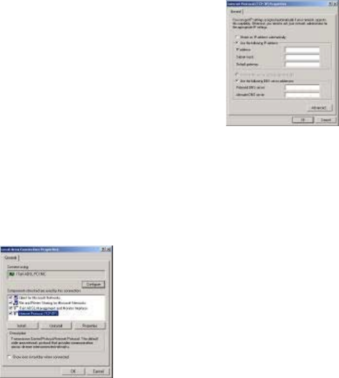
4. The Internet Protocol (TCP/IP)
window appears. Under the General
tab, enable Use the following IP
address. The default settings for IP
configurations will turn from gray to
clear. Enter in the IP address, Subnet
Mask, and Default Gateway supplied
by your ADSL service provider. Click
OK.
5. The previous General Tab window
a
pp
ears. Click O
K
.
25
6. The Network and Dial-up Connection
window appears. CLOSE this window
and your connection is complete.
Congratulations, you are done. Your ADSL Internet connection is established!

26
2. The Connect My Connection window
will appear. Enter your User Name and
Password supplied by your ADSL
service provider. You are now ready to
make a network connection. Click Dial.
3. The Connection complete window
appears, click OK.
Making an ADSL connection
RFC 2364 - Point-to-Point Protocol over ATM – 2000
Congratulations, you are done. Your ADSL connection is established!
1. Double-click on the ITeX PPPoA icon
that a
pp
ears on
y
our deskto
p
.

27
Windows NT4.0
RFC 1483 – Bridged Ethernet over ATM
RFC 1577 - Classical Internet
Protocol over ATM
1. On your desktop, double-click My
Computer, and then double-click
Control Panel.
2. In the Control Panel window, double-
click the Network icon. The Network
window appears. Select the Adapters tab
and then click Add.
3. The Select Network Adapter window
appears. Click Have Disk.
4. Insert ADSL Driver CD-ROM into
your systems CD drive.
5. The Insert Disk window appears. Click
Browse to locate the driver on your CD-
ROM for the protocol supported by your
ADSL provider: 1483NT4 or 1577NT4
(The example uses “d” as the CD -ROM
drive letter. Your drive may have a
different letter.) Click OK.
6. The Select OEM Option window will
find the ITeX ADSL PCI NIC, Click
OK.

28
7. The Network window will appear.
Click the Adapters tab to verify that
the ITeX ADSL PC NIC has been
found. Click on the Protocols tab and
verify that the ADSL Management
and Monitor Interface is present.
NOTE: To review the Network
window properties at any time, right-
click the Network Neighborhood icon
and select Properties.
NOTE: If no previous network devices
have been installed, then the Network
Neighborhood icon will not be present
on your desktop. To open the Network
window, double-click My Computer
then Control Panel then Network.
8. The Microsoft TCP/IP Properties
window appears. Enter in the IP
Address, Subnet Mask and Default
Gateway supplied by your ADSL
service provider. Click OK.
9. The Network Settings Change window
appears. You must now re-start your
computer for the settings to take effect.
Click Yes.
29
10. You must now set the ADSL configuration. Go to page 27.
NOTE: The service mode type will be one of
the following:
!!ANSI T1.413 Issue 2
!!ITU G.992.2 Annex A (G.lite)
!!ITU G.992.1 Annex A (G.dmt)
WINDOWS NT 4.0
1. After your PC has rebooted, right-click
on the Mapi Icon, and select the
Configuration option.
2. The Configuration window appears.
This is the Network Protocol and
PVC settings section. Enter in the
VPI, VCI, and Framing values
supplied by your ADSL service
provider.
3. In the Select ADSL Mode section,
select the mode(s) recommended by
your ADSL service provider. Click on
the mode(s) required and then click on
4. The PVC Setup window appears.
Click Yes to restart your PC system
and to allow the new changes to take
effect
SETTING THE ADSL CONFIGURATION FOR
RFC 1483 OR RFC 1577

30
5. Now you must create a Dial-up Connection. Please go to page 32.

31
Windows NT4.0
RFC 2364 – Point to Point Protocol over ATM
1. On your desktop, double-click My
Computer, and then double-click Control
Panel.
2. In the Control Panel window, double-
click the Network icon. The Network
window appears. Select the Adapters tab
and then click Add.
3. The Select Network Adapter window
appears. Click Have Disk.
4. Insert the ADSL Driver CD-ROM into
your systems CD drive.
5. The Insert Disk window appears. Click
Browse to locate the driver on your CD-
ROM for the protocol supported by your
ADSL provider: 2364NT4 (The example
uses “d” as the CD-ROM drive letter.
Your drive may have a different letter.)
Click OK.
6. The Select OEM Option window will
find the ITeX ADSL PCI NIC, Click OK.

32
7. The Setup Message window appears.
Click OK.
8. The Windows NT Setup window
appears. Insert your NT4.0 CD-
ROM into the PC system CD drive,
and type in “D:\i386” Click
Continue.
9. The Add RAS Device window appears.
Click on the “Scroll arrow” to locate
ISDN1-itexwana. Then click OK.
10. The Remote Access Setup window
appears. Click Continue.
11. The Network window will appear. Click
the Adapters tab to verify that the ITeX
ADSL PC NIC has been found. Click on
the Protocols tab and verify that the
ADSL Management and Monitor
Interface is present. Click on the
Services tab to verify that the Remote
Access Service is present. Then click
Close.
NOTE: To review the Network window
properties at any time, right-click the
Network Neighborhood icon and select
Properties.
NOTE: If no previous network devices

33
have been installed, then the Network
Neighborhood icon will not be present on
your desktop. To open the Network
window, double-click My Computer then
Control Panel then Network.
12. The Network Settings Change window
appears. You must now re-start your
computer for the settings to take effect.
Click Yes.
13. You must now set the ADSL configuration for RFC 2364. Go to page 31.
34
NOTE: The service mode type will be one of
the following:
!!ANSI T1.413 Issue 2
!!ITU G.992.2 Annex A (G.lite)
!!ITU G.992.1 Annex A (G.dmt)
WINDOWS NT 4.0
1. After your PC has rebooted, right-click
on the Mapi Icon, and select the
Configuration option.
2. The Configuration window appears.
This is the Network Protocol and
PVC settings section. Enter in the
VPI, VCI, and Framing values
supplied by your ADSL service
provider.
3. In the Select ADSL Mode section,
select the mode(s) recommended by
your ADSL service provider. Click on
the mode(s) required and then click on
4. The PVC Setup window appears.
Click Yes to restart your PC system
and to allow the new changes to take
effect.
SETTING THE ADSL CONFIGURATION FOR
RFC 2364
5. You must now create a Dial-up Network Connection. Please go to page 32.

35
WINDOWS NT4.0
CREATING A DIAL-UP NETWORK CONNECTION
2. The Dial-Up Networking window
appears and prompts for the phone
number of the dial-up server. Unless
instructed to enter a phone number by
the ADSL service provider, enter zero
“0”. Click Dial.
3. The Connect to MyDialUpServer
window appears. Enter the User name,
Password and Domain supplied by your
ADSL service provider. Click OK.
NOTE: If this screen persists and a
connection logon error is reported,
confirm that the correct User name and
Password are entered and try the
connection again. Also verify that the
connection address is correct.
4. The Connection Complete window is
displayed at the completion of a
successful Dial-Up logon. Choose a
display behavior and click OK to close.
Congratulations, you are done. Your ADSL Internet connection is established!
2. Double-click on the ITeX PPPoA icon
that appears on your desktop.

36
Editing Your Service Connection
Service Connection
1. To view or edit the ADSL connection service address, right-click the Diagnostic
Tool icon (located on the Taskbar), and select the Configuration option.
2. The PVC Setup (Permanent Virtual Connection) window displays the connection
service address. Click Close to exit window.
3. To edit the connection service address, select and enter the VPI and VCI address in
the field shown and click PVC Setting.
4. To accept a Connection Address that has been changed (restart the PC System),
click Yes.
NOTE: A PC system restart will begin once the connection address change is
accepted.
IP Configuration
1. This section includes the IP configuration specifics for Windows NT4.0. The NT 4.0
windows are slightly different from those of Windows 95 /98. Other than minor
screen differences, the process for editing the IP address settings is the same for
Windows NT 4.0 and Windows 95/98.
2. At your desktop, double-click My Computer, then double-click Control Panel to
view the contents of the control panel. In the Control Panel window, double-click
the Network icon.
Note: The Network window shortcut is a right-click on the Network
Neighborhood icon on your desktop, and then a left-click on Properties.
3. Select the Protocols tab of the network window. Select TCP/IP Protocol and click
Properties.
4. Select the IP address option and note that the IP Address and Subnet Mask regions
will turn from gray to active .
5. Enter the IP Address (e.g. 192.168.4.39) and Subnet mask (e.g. 255.255.255.0).
6. Enter the Default Gateway in this window, and then enter the Host Name and
Domain.
NOTE: Please refer to your ADSL service provider. To enter the Domain search
(DNS) entries, click Add, then enter the address. Click Add to save the address.
Repeat the process for additional DNS entries. Click OK to update the changes.
37
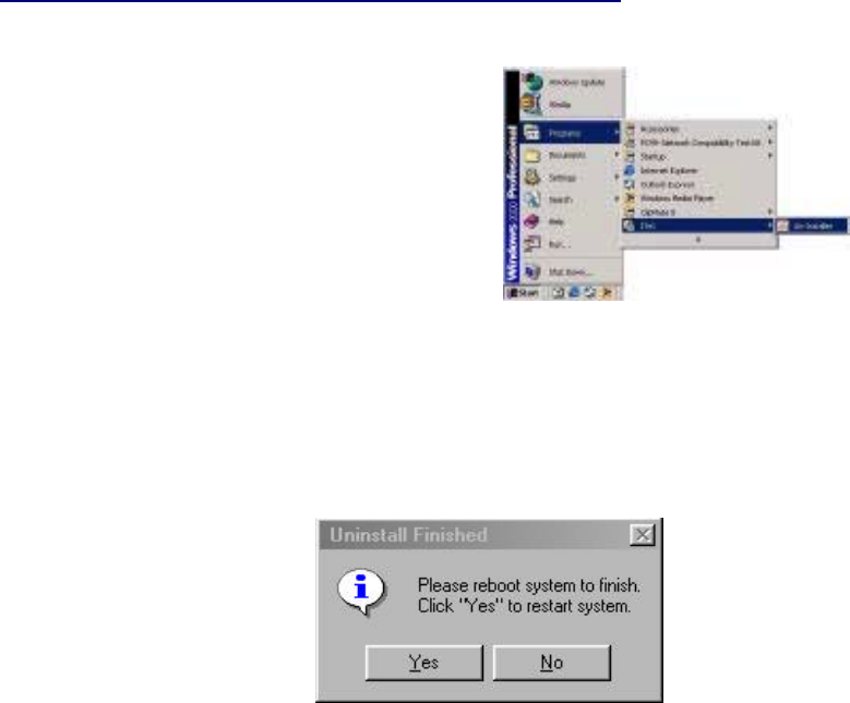
Removing Drivers
Windows 95, 98 WINDOWS NT4.0 WINDOWS 2000
1. On the desktop, click the
START Menu on the Task
Bar.
2. Select Programs. The system
window appears.
3. Select the ITeX Tab, and then
click on the Un-Installer Tab.
Note: For W95-98-NT4, an Uninstall Finished windows message appears. Click
Yes to restart your system and confirm chan
g
es.

38
Diagnostic Tools
The diagnostic tool icon allows the user to monitor the ADSL connectivity, setup the
service connection address, and run diagnostic tests. The Diagnostic Tools icon is
displayed on the task bar as shown. By positioning the mouse cursor over the icon, the
upstream and downstream rates are displayed.
The Diagnostic Tool icon consists of two lights side by side. The left light indicates data
is being transmitted whereas the right light indicates data is being received. The state of
the connection can be determined as follows:
Color Code Description
Red, Red No ADSL connection and No ADSL handshaking. Check your cable
co
nn
ect
i
o
n
s.
Black,
Yellow or
Yellow/Blac
ADSL handshaking – Connection not established. Precursor to
establishing an ADSL connecting.
Black,
Black
ADSL connection established – no data traffic or idle connection
Black, ADSL connection established
–
NIC is receivin
g
data
(
TX/off,
Green, ADSL connection established
–
NIC is transmittin
g
data
(
TX/on,
Green,
Green
ADSL connection established – NIC is transmitting and receiving data
(TX/on, RX/on)
? NIC is disconnected or a driver problem exists.
On the Diagnostic Tool icon, located on the right
hand side of the status bar, right-click the icon to
display the menu, then click Open. The ADSL
Diagnostic Tool window appears on your desktop.
The four tabs of the Diagnostic Tools are ADSL
Status, Diagnostic, ADSL Statistics and
Configuration.
ADSL Status window displays the current state of
the ADSL connection, including the current ADSL
State, ADSL protocol in use, and the Net Data Rates
for upstream and downstream data.
NOTE: ADSL protocols supported by the ADSL
drivers are T1.413, G.dmt and G.lite. The protocol
must be supported also by the ADSL equipment
located at the central office.
ADSL Statistic window keeps tabs on errors that
might affect overall system performance. The counts
are reset whenever the PC system is restarted.
Maximum receiving rate
Maximum transfer rate

39
Re-training Count tracks the number of ADSL
connections performed. Due to unexpected line
condition changes, the drivers can re-train the
connection causing the Re-training Count total to
increment. The Diagnostic Tool icon will flash yellow
while reconnecting.
ADSL implements Reed Solomon (RS) error
checking:
FEC Count tracks the forward error correction
count.
CRC Count tracks the accuracy of correcting data
errors over each 17msec.
ATM HEC Count (header error check) errors are
recorded as an indication of ATM packet accuracy.
As a measure of packet transfer performance, the
Packet Errors
are cou
n
ted a
n
d tracked aga
in
st the
The Diagnostic window is used to verify the ADSL
modem card functionality. Running the Diagnostic
program will disconnect the NIC from the ADSL
line. Close all Dial-up sessions and close all files
b
efore running the Diagnostic program. Product
Information (e.g. driver revisions) is displayed by
clicking the Product Info tab.
Product Information lists the versions of the
Diagnostic Tools and the driver version. The DLL
version describes the software being used by both
the dr
i
vers a
n
dD
i
ag
n
ost
i
c Tool software.
Click Run Diagnostics to run the diagnostic
program that will test PC functionality and report
the status. A warning message pops up that the
ADSL service will disconnect before performing the
diagnostic test. If connected to the Internet at this
time, disconnect any Dial-up sessions. Click Yes to
b
egin the diagnostic program or click No to exit
diagnostic program. The diagnostic program
performs a brief hardware check and displays the
hardware status

40
The ADSL modem card is equipped with a RJ-11 jack for
connection to the ADSL data port. The center two pins, pins 2
and 3, are used for ADSL data. For the card to make a proper
ADSL connection, the installed ADSL data port should also use
pins 2 and 3 for data. If the ADSL data port installation uses pins
1 and 4 for data, then a wiring converter will be required. Do not
alter or remove the wiring converter if present. Consult with your
ADSL provider before attempting any wiring changes.
Connector Pin-out
LED functions for the Apollo 3
Modem
LED Status Signals Description
Green LED on
t
om
PWR On 0.5s, Off 0.5
s
O
n
M
odem initialized, idle
mode (disconnect)
Power Supply OK
G
reen LED on Top SYNC On 0.25s, Off 0.25
s
(On 0.25s, Off 0.25s) x 2,
Off 0.5s
M
odem Connectin
g
Modem Connected
Yellow LED
on Top DATA On TX or RX
s
mission,
Off no data
ATM data transmission
(in showtime status)
R
ed LED on Bottom ERR On 0.25s on any CRC
r
ATM data transmission
(in showtime status)
All 4 LED
All On
D
river not installed or

41
System Requirements & Compliance Certification
System Requirements
!!IBM PC/AT or compatible
!!Pentium 100Mhz or faster
!!30Mbytes available hard disk space or more
!!2x CD-ROM drive or better
!!32Mbyte available system memory or more
Power Requirements
!!0.75A Max @ +5V ? 5%, 0.1A max @ ? 12V, ? 5%
Environmental Requirements
!!Operating Temperature: 0 ?C to 70?C with airflow
!!Non-operating Temperature: -10 ?C to 85 ?C
!!Operating Humidity: 10% to 90% non-condensing
!!Non-operating storage humidity: 5% to 95% non-condensing
Compliance Certification
!!UL 1950
!!CE approved
!!FCC Part 15 Class B
Copyright & Regulatory Information
Copyright ? 2000, Integrated Telecom Express, Inc. All rights reserved.
This manual and software described in it are copyrighted with all rights reserved. This
manual may not be copied, in whole or in part, without written consent. All product
names are trademarks and or registered trademarks of their respective companies.
FCC Statement
This equipment has been tested and found to comply with the limits for a Class B
digital device, pursuant to Part 15 of the FCC Rules. These limits are designed to
p
rovide reasonable protection against harmful interference in a residential installation.
This equipment generates, uses and can radiate radio frequency energy and, if not
installed and used in accordance with the instructions, may cause harmful interference
to radio communications. However, there is no guarantee that interference will not
occur in a particular installation. If this equipment does cause harmful interference to
radio or television reception, which can be determined by turning the equipment off
and on, the user is encouraged to try to correct the interference by one or more of the
following measure:
!!Reorient or relocated the receiving antenna.
!!Increase the separation between the equipment and receiver.
!!Connect the equipment into a different outlet circuit from than the receiver.
!!Consult an experienced radio/TV technician for help.
CAUTION: Any changes of modifications not expressly approved by the
grantee of this device could void the users authority to operate
the equipment.