UAT AR-5153 ADSL Router / Bridge User Manual Manual rev0 1
UAT Inc. ADSL Router / Bridge Manual rev0 1
UserManual.wiki
>
UAT
>
AR 5153 User Manual
User Manual
Navigation menu
Upload a User Manual
Namespaces
Wiki Guide
HTML
PDF
Info
Views
User Manual
Discussion / Help
Navigation
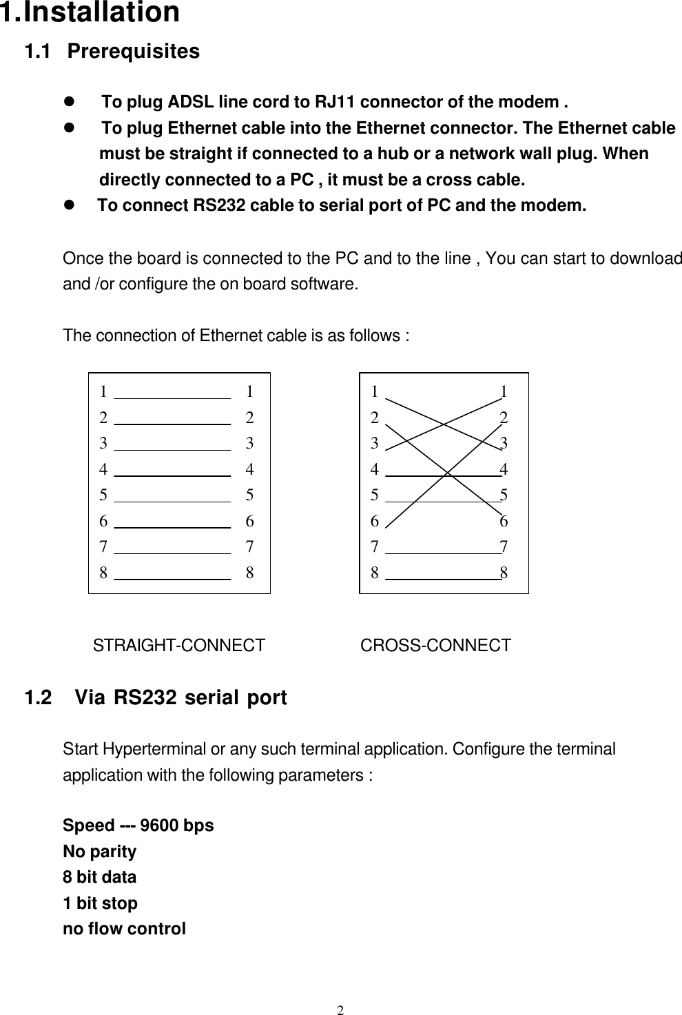
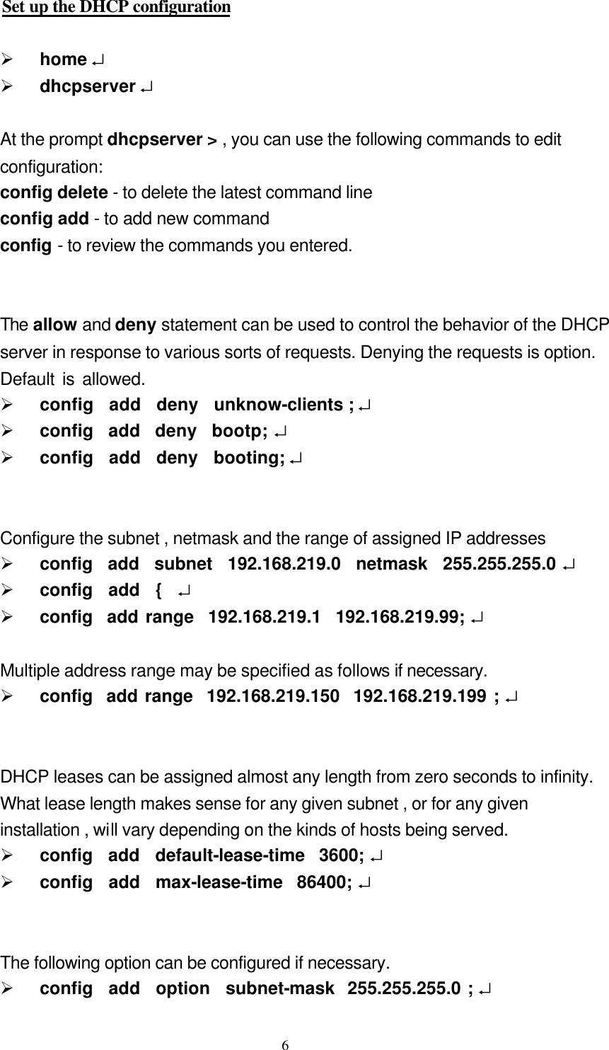
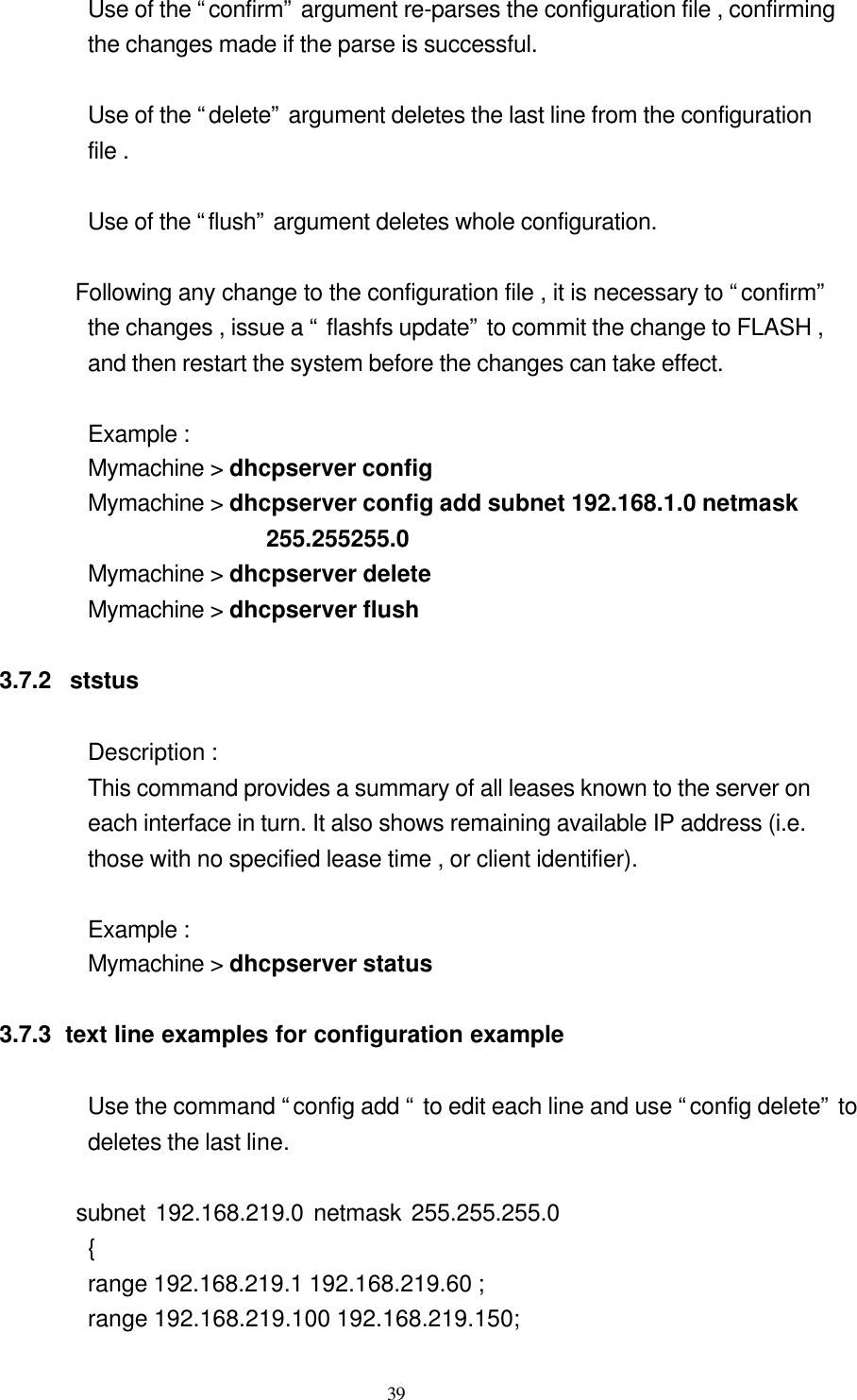
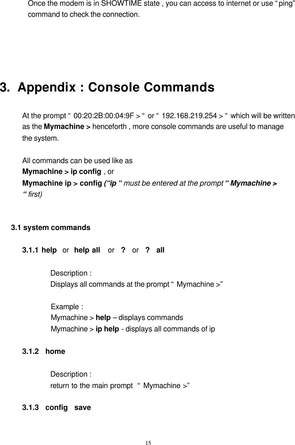
![7Ø config add option broadcast-address 192.168.219.255 ; ↵ Ø config add option routers 192.168.219.254 ; ↵ ( The routers option specifics a list of IP address for routers on the client’s subnet. Router should be listed in order of preference . The option can be configured as : option routers ip-address [, ip-address ….] ; ) Ø config add option domain-name-servers aaa.bbb.ccc.ddd ↵ (aaa.bbb.ccc.ddd is the IP address of DNS server. The option can be configured as : option domain-name-servers ip-address [ , ip-address …]; ) Ø config add option lpr-servers eee.fff.ggg.hhh ; ↵ ( eee.fff.ggg.hhh is the line printer server available to the client . Servers should be listed in order of preference. The option can be configured as : option lpr-servers ip-address [ , ip-address …. ] ; ) Ø config add } ↵ Ø config confirm ↵ Save the configuration and reboot the system Ø home ↵ Ø flashfs update ↵ Ø restart ↵ Note : Before an IP address assigned to ethernet port of the modem , the function of DHCP server is inactive. 2.3.2 Disable the DHCP Server To disable the DHCP configuration , the configuration information previously supplied needed to be flushed. To do so , issue the following commands. Flush the DHCP configuration Ø dhcpserver ↵](https://usermanual.wiki/UAT/AR-5153/User-Guide-139285-Page-7.png)
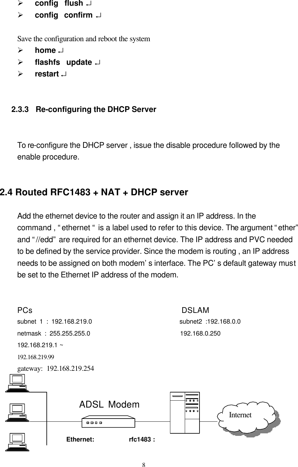
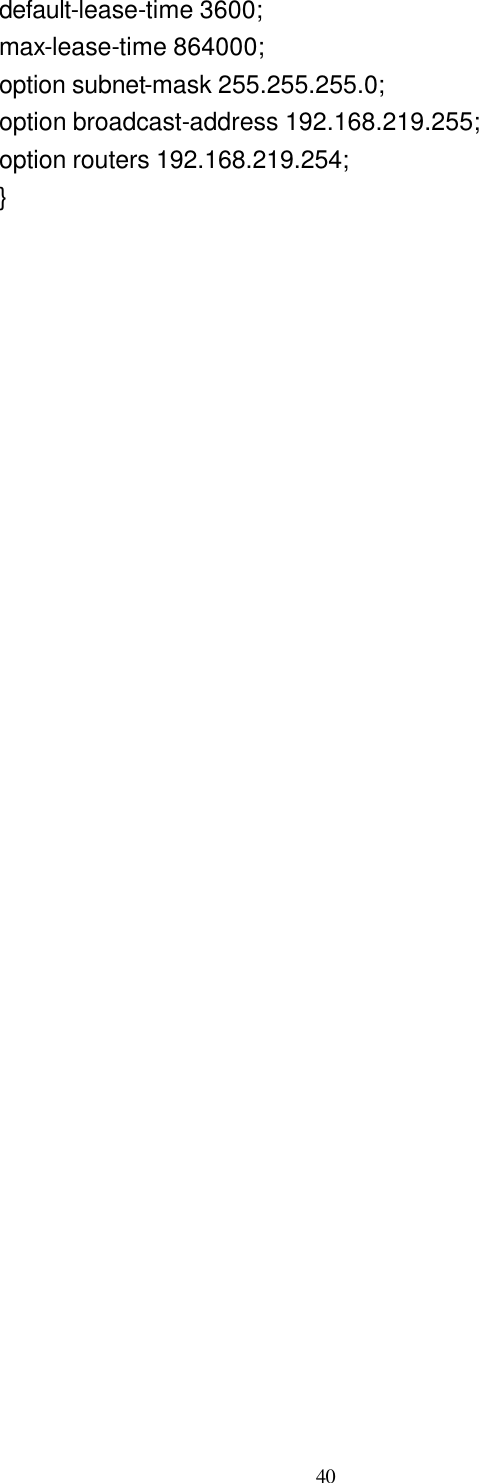
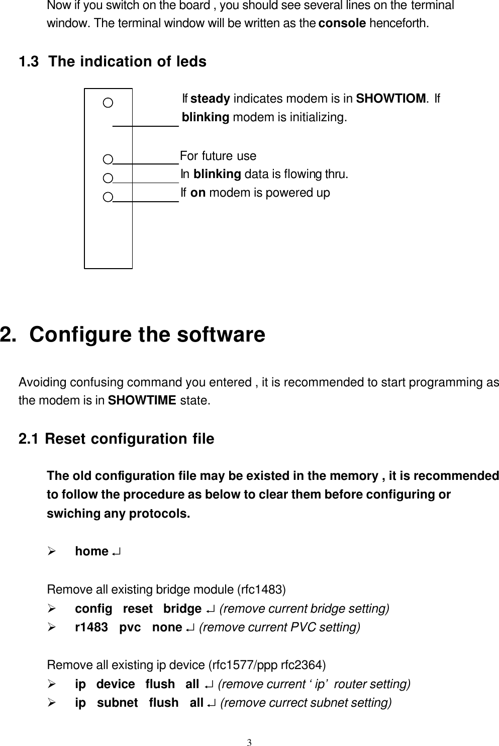
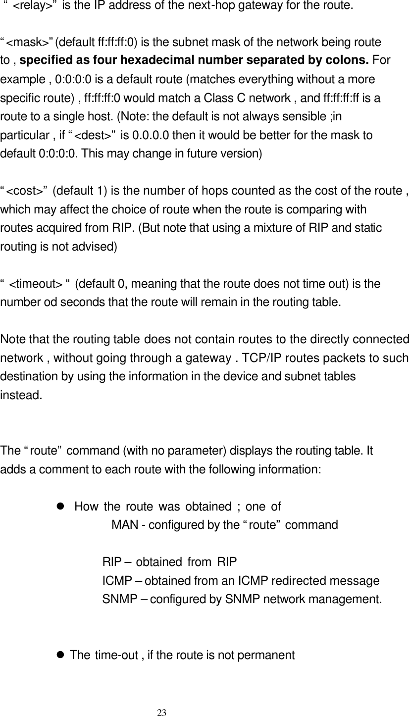
![16 Description : save configuration Example : Mymachine > config save 3.1.4 restart Description : reboot the system Example : Mymachine > restart 3.2 ip commands 3.2.1 config [save] Description : Displays the IP configuration (not including the “snmp” configuration ), or save it in flash memory. Example : Mymachine > ip config Mymachine> ip config save 3.2.2 device device add < i/ f > <type> [< file >] [ < IP address ] device delete < i / f > device flush Description : Displays the interfaces that IP is configured to use , or adds an interface to the configuration , or delete an interface , or all interfaces , from the configuration. i/f ( interface ) – ethernet , ppp_device , ipoa , rfc1483 type – ether , atm , atmpvc](https://usermanual.wiki/UAT/AR-5153/User-Guide-139285-Page-16.png)
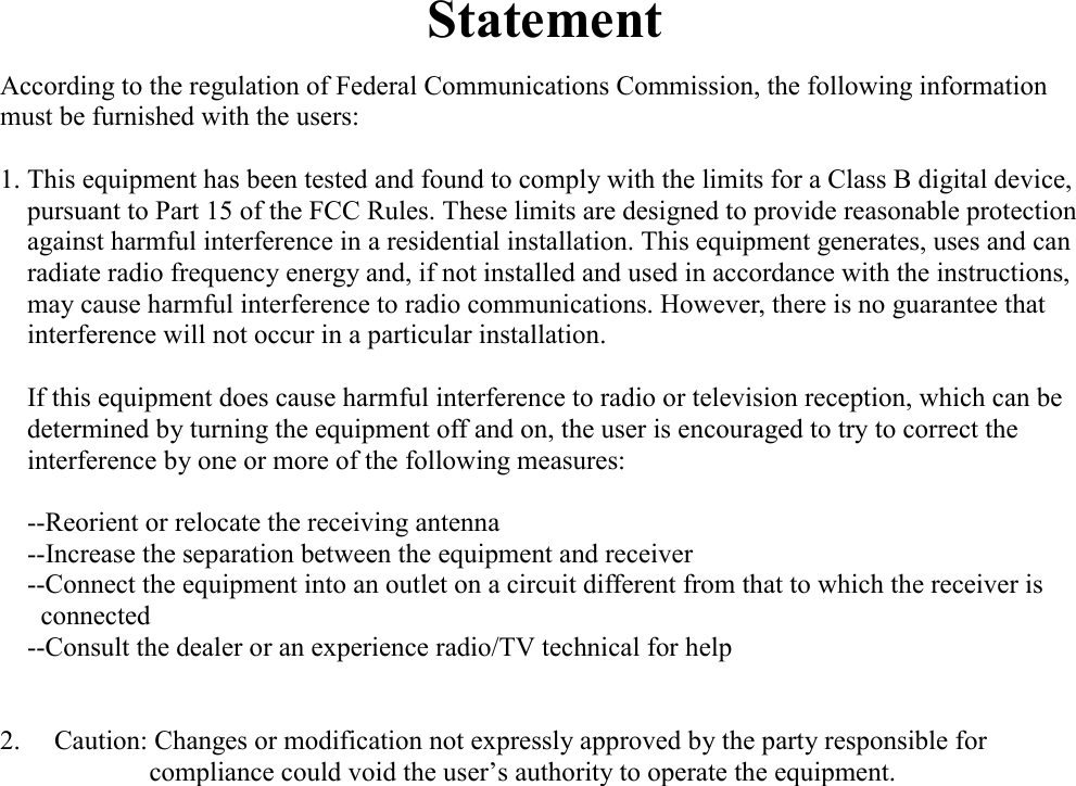
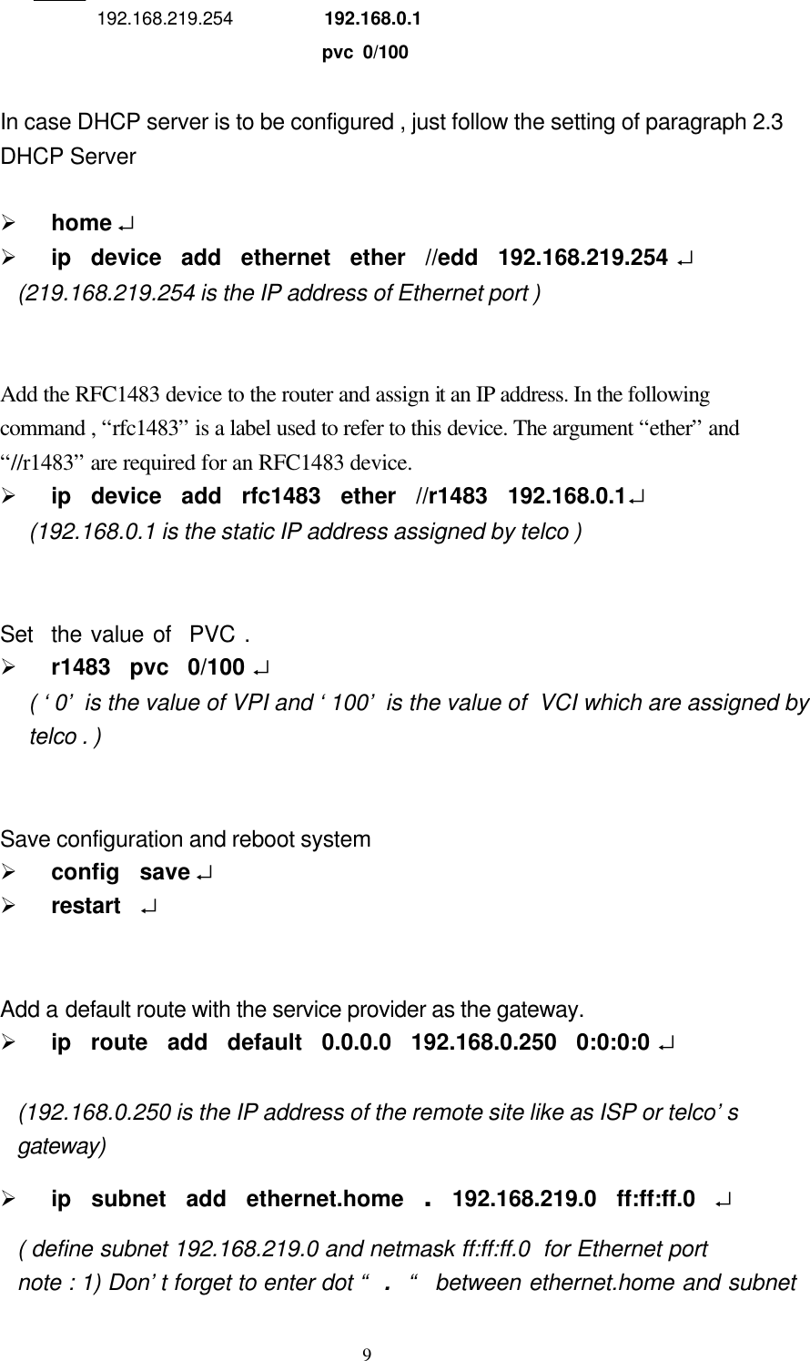
![17 file - //edd , //atm , //r1483 , //ppp Configuration saving saves this information. Example : Mymachine > ip device Mymachine > ip device add ethernet ether //edd 192.168.219.254 3.2.3 disable [ < i/ f >] Description : Disable all interface , or just a specified interface. Example : Mymachine > ip disable ipoa 3.2.4 enable [ < I / f > ] [mtu <size] [ < IP address > ] Description : Enable all interface , or just a specified interfaces. Can also be used to set the MTU and IP address on an interface when enabling it (or change them on an interface that is already enabled) . Configuration saving saves this information. Example : Mymachine > ip enable ipoa 192.168.219.254 3.2.5 help help <cmd> help all Description : Displays a summary of available commands ,more detailed information on a particular command , or more detailed information on all commands. Example :](https://usermanual.wiki/UAT/AR-5153/User-Guide-139285-Page-17.png)
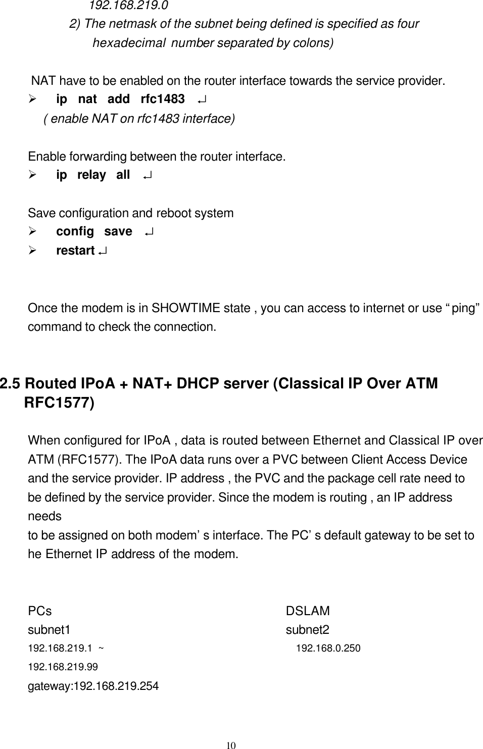
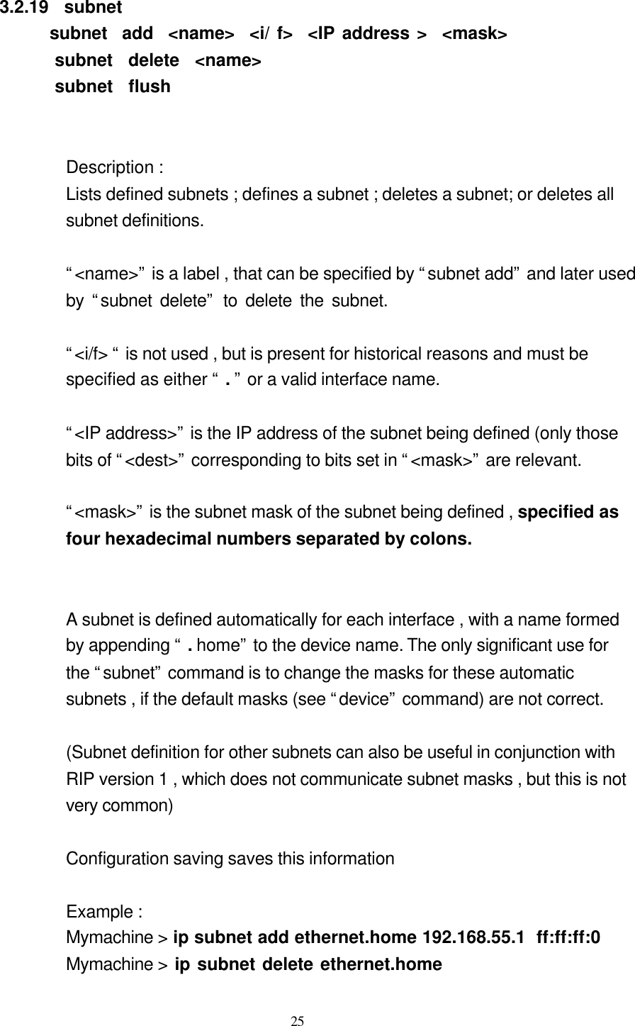
![18 Mymachine > ip help Mymachine > ip help all Mymachine > ip ipatm help all 3.2.6 ipatm pvc ipatm pvc add < I / f> < vci >/[<IP address>] [<pcr>] [<port>] ipatm pvc delete <vci> [<port>] ipatm pvc flush Description : Lists configured PVCs for use by IP-over-ATM; configures another ;deletes one; or deletes all. “ < I / f > is the name of an interface configured for IP-over-ATM using PVCs. “ < vci > is the VCI to use for the PVC. The range of possible VCIs depends on the system. “ < IP address >” is the IP address of the machine at the other end of the PVC. If it is not specified , TCP/IP will use Inverse ATMARP(RFC1577) to determine the IP address; if it is specified , then Inverse ATMARP will not be used. “ < pcr> “ is the peak cell rate , in cells per second. The default is 60000. (If neither IP address nor PCR is specified , the “/” after the VCI can be omitted) “ < port >” is the port name : it must be specified if the machine is a switch, and not otherwise. Configuration saving saves this information. Example :](https://usermanual.wiki/UAT/AR-5153/User-Guide-139285-Page-18.png)
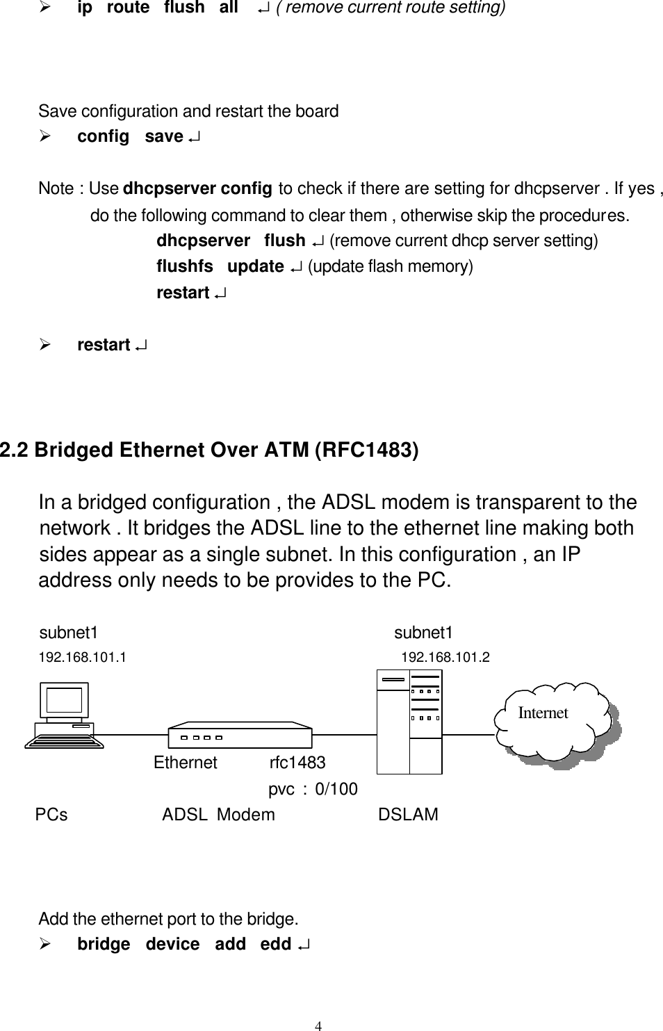
![19 Mymachine > ip ipatm pvc add atm 60 a3 Mymachine > ip ipatm pvc add atm 61//50000 b1 Mymachine > ip ipatm pvc 3.2.7 norelay [ all | < i/f > [ <i/f > ] [forward] ] Description : Turns off forwarding between interfaces ; see the “ relay” command for more details. The command “norelay” with no parameters is equivalent to “norelay all” : it turns off all forwarding. Configuration saving saves this information. Example : Mymachine > ip norelay Mymachine > ip norelay etherer ppp_device forward 3.2.8 ping < IP address > Description : Sends an ICMP Echo message to the specified address. Example : Mymachine > ip ping 192.168.4.1 3.2.9 relay relay all | < i/ f > [ < i/ f > ] [forward] Description : Displays or sets what forwarding TCP/IP will do between interfaces . The combinations of setting forwarding can be a bit confusing ; they behave as follows : “ < i/f> “ - means interface .](https://usermanual.wiki/UAT/AR-5153/User-Guide-139285-Page-19.png)
![20 “forward” indicates one-way relaying relay all : from every interface to every non-loopback interface. relay if1 : from if1 to every non-loopback interface , and from every interface to if1 relay if1 forward : from if1 to every non-loopback interface . relay if1 if2 : from if1 to if2 and from if2 to if1 relay if1 if2 forward : from if1 to if2 To disable forwarding , use the “norelay “ command. Configuration saving saves this information. Example : Mymachine > ip relay Mymachine > ip relay all 3.2.10 restart Description : Reboots the system. 3.2.11 rip accept [ all | <i/f> [none | <version>] Description : Controls for which version or version of RIP (RIP v1 , FC1058 , or RIP v2 ,RFC1723) TCP/IP will accept incoming information on each interface. By default both RIP version are accepted on all interface (“rip accept all 1 2 “). Configuration saving saves this information. Example : Mymachine > ip rip accept all 1 2 Mymachine > ip rip accept ethernet 2](https://usermanual.wiki/UAT/AR-5153/User-Guide-139285-Page-20.png)
![21 3.2.12 rip allowed Description : Displays the RIP version that will be accepted and send on each interface. Example : Mymachine> ip rip allowed 3.2.13 rip boot Description : Broadcasts a request for RIP information from other machines. TCP/IP does this automatically when it first starts up, and the routing information should be kept up to date by regular broadcast from the other machines , so this command is normally of little use. Example : Mymachine > ip rip boot 3.2.14 rip help [ < cmd> | all ] Description : Displays help on “rip” subcommands Example : Mymachine > ip rip help Mymachine > ip rip help boot 3.2.15 rip rxstatus Description : Displays the status of the RIP package reception mechanism. This command is of little or no use except for debugging.](https://usermanual.wiki/UAT/AR-5153/User-Guide-139285-Page-21.png)
![22 Example : Mymachine> ip rip rxstatus 3.2.16 rip send [all | <i/f>] [none | <version>] Description : Controls which version or versions of RIP (RIP version1,RFc1058 ,or RIP version2 ,RFC1723) TCP/IP will use to broadcast routing information on each interface. If both version are specified , routing information is broadcast in duplicate , once using each version. Specifying “all” affects all interfaces except the loopback interface (if any) By default RIP version 2 only is used on all non-loopback interfaces (“rip send all 2”) Configuration saving saves this information. Example : Mymachine > ip rip send all 2 Mymachine > ip rip send ethernet 1 3.2.17 route route add <name> <dest> <relay> [<mask>] [<cost>] [<timeout>] route delete <name> route flush Description : Lists routes ; add or delete a static route ; or delete all routes. “ <name>” is an arbitrary name specified to “route add “ that can be used to delete the route using “route delete”. “ <dest>” is the IP address of the network being routed to (only those bits of “<dest>” corresponding to bits set in “<mask>” are relevant.](https://usermanual.wiki/UAT/AR-5153/User-Guide-139285-Page-22.png)
![24 l The original time-out , if the route is not permanent l The name of the interface ( if known) that will be used for the route l An asterisk ( “ ★ ”) if the route was added recently and RIP has not yet processed the change . (the asterisk should disappear within 30 seconds , when RIP next considers broadcasting routing information) Configuration saving saves this information. (only the routes configured by the “route” command are saved or displayed by “ config”) Example : Mymachine > ip route add default 0.0.0.0 192.168.2.3 0:0:0:0 Mymachine > ip route add testnet1 192.168.101.0 192.168.2.4 Mymachine > ip route add testnet2 192.168.102.0 192.168.2.34 ff:ff:ff:0 1 60 Mymachine > ip route 3.2.17 routes Description : Lists routes ( The same as “routes” , with no parameter) Example : Mymachine > ip routes 3.2.18 stats arp | icmp | ip | tcp | udp [reset] stats help [ <cmd> | all ] Description : Displays or clears a subnet of IP statistics. Example : Mymachine > ip stats udp Mymachine > ip stats tcp reset](https://usermanual.wiki/UAT/AR-5153/User-Guide-139285-Page-24.png)
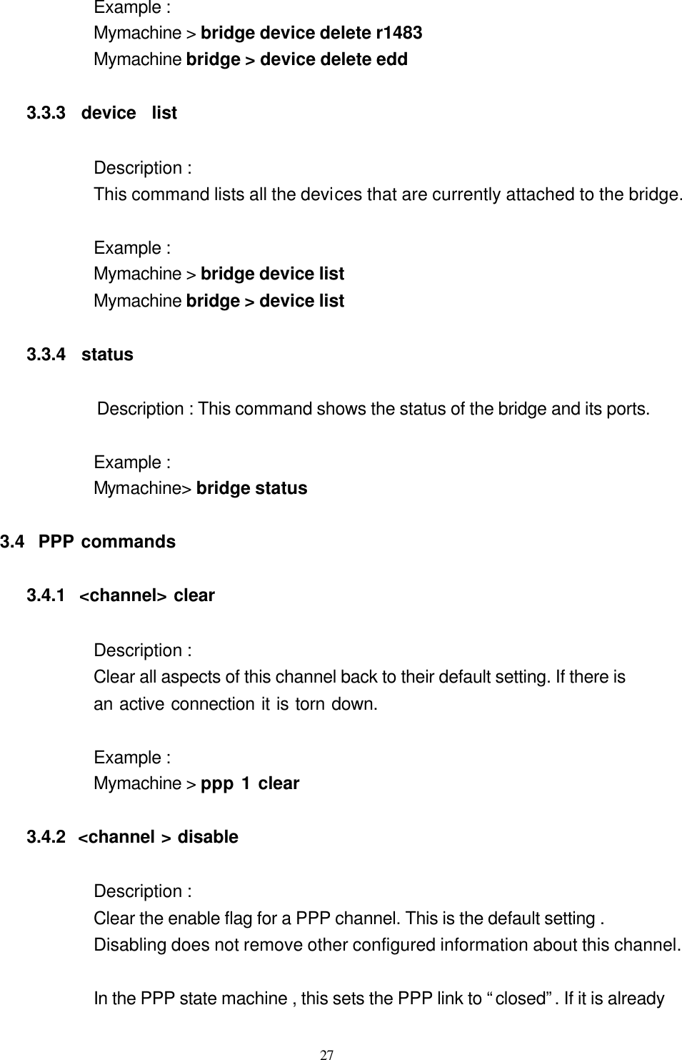
![28 closed , there is no effect. Configuration saving saves this information. By default all channels are disabled. Example : Mymachine > ppp 1 disable 3.4.3 <channel> enable Description : Set the enable flag for a PPP channel. By default this is disabled. In the PPP state machine , this flag sets the PPP link to “open” . If it is already open , there is no effect. Configuration saving saves this information. Example : Mymachine > ppp 1 enable 3.4.4 < channel> info [all] Description : Provide information about the current setting of this channel. This includes all configuration state , and also current protocol information. Example : Mymachine> ppp 1 info all 3.4.5 < channel> interface <n> Description : Logically associated the specified channel with the specified interface. Interface 1 is always the router port. It should be used for any PPP channel over which IPCP communication with the local system’s IP router is desired. Other interfaces can be created for bridging. A single PPP channel can only be associated with a single interface ,or a single tunnel.](https://usermanual.wiki/UAT/AR-5153/User-Guide-139285-Page-28.png)
![29 Use info to find the current setting. Calling with n=0 removes any association. This is the default state. Configuration saving saves this information. Example : Mymachine > ppp 1 tunnel <n> 3.4.6 < channel> llc [1 | 0] Description : If 1 , use an LLC header on the front of transmitted packets and require one on received ones. This consists of four bytes , FE-FE-03-CF , and is required for PPP over AAL5 (RFC2364 p4) when using LLC encapsulated PPP. If 0 , disable this. The default value is 0 ( disabled ) Configuration saving saves this information. Example : Mymachine > ppp 1 llc 1 3.4.7 <channel > pvc none < channel> pvc [ [< port>] <vpi>] <vci> [ ip | mac ] [listen] Description : Attached an ATM PVC to the given PPP channel. The port can be specified (only for a multi-port device ), and VPI(default VPI is 0) ,and the VCI. The allowable range of port , VPI , VCI depends on the atm driver . Normal limits are 0 for port , 0 only for VPI , 1…1023 for VCI. If a single argument none is supplied , any current connection is torn down. Note that enable must also be used to allow the link to become operational. The ip and mac indicates which form of data is transported over the connection: one of IP data (controlled by the IPCP protocol) , or MAC data](https://usermanual.wiki/UAT/AR-5153/User-Guide-139285-Page-29.png)
![30 (for BCP) . If neither is provided , ip is assumed. If the channel is not linked to an interface , and the channel is for IP data , the channel is linked to interface 1 . If the channel is not linked to an interface , and the channel is for MAC data , the channel is linked to interface 2 . If listen is specified then this is the server end of a PVC . It will not send out PPP configure Request until it first receives a packet over the PVC. When a connection is torn down it goes returns to this state. Use the info command to read this information. Configuration saving saves this information. Example : Mymachine > ppp 3 pvc 3 32 (set channel 3 to be (VPI=0,VCI=32) Mymachine > ppp 4 info (read PVC setting for channel 4) Mymachine > ppp 5 pvc 0 (remove any PVC setting from channel 5) 3.4.8 <channel> qos [cbr | ubr] [pcr <pcr-tx > [ <pcr-rx> ] ] Description : Specified that the VC for a PPP channel should be Constant Bit Rate or Unspecified Bit Rate , and (optionally for UBR) give a Peak Cell Rate for the connection. If two values are specified then they are transmit and receive PCRs respectively. By default channels are established UBR. Configuration saving saves this information. Examples : my machine > ppp 3 qos cbr pcr 10000 (set channel 3 to be CBR limited at 10000 cells /sec.](https://usermanual.wiki/UAT/AR-5153/User-Guide-139285-Page-30.png)
![31 3.4.9 <channel> remoteip [ <IP address> ] Description : If a PPP link is established using IPCP , this call causes the channel to provide the given IP address to the remote end of the connection. PPP will refuse to complete the connection if the other end will not accept this. This is normally used for channel on which the remote party dials in , to allocate the IP address to that remote party. Call with no argument to find the current setting. Call with 0.0.0.0 to remove any setting. This is the default state. Configuration saving saves this information. Example : Dial –in : Mymachine > ip device add ether ether //edd 192.168.219.254 Mymachine > ip device add ppp_device ether //ppp/DEVICE=2 192.168.1.2 Mymachine > ppp user add peter pwd telecom chap (user name :peter , password : telecom”) Mymachine > ppp 2 pvc 0 100 ip listen Mymachine > ppp 2 interface 2 Mymachine > ppp 2 remoteip 192.168.1.1 Mymachine > ppp 2 theylogin chap Mymachine > ppp 2 enable Mymachine > ip relay all Mymachine > config save Mymachine > restart 3.4.10 <channel> they login pap|chap|none Description : This command describes how we requires the far end to login on this channel.](https://usermanual.wiki/UAT/AR-5153/User-Guide-139285-Page-31.png)
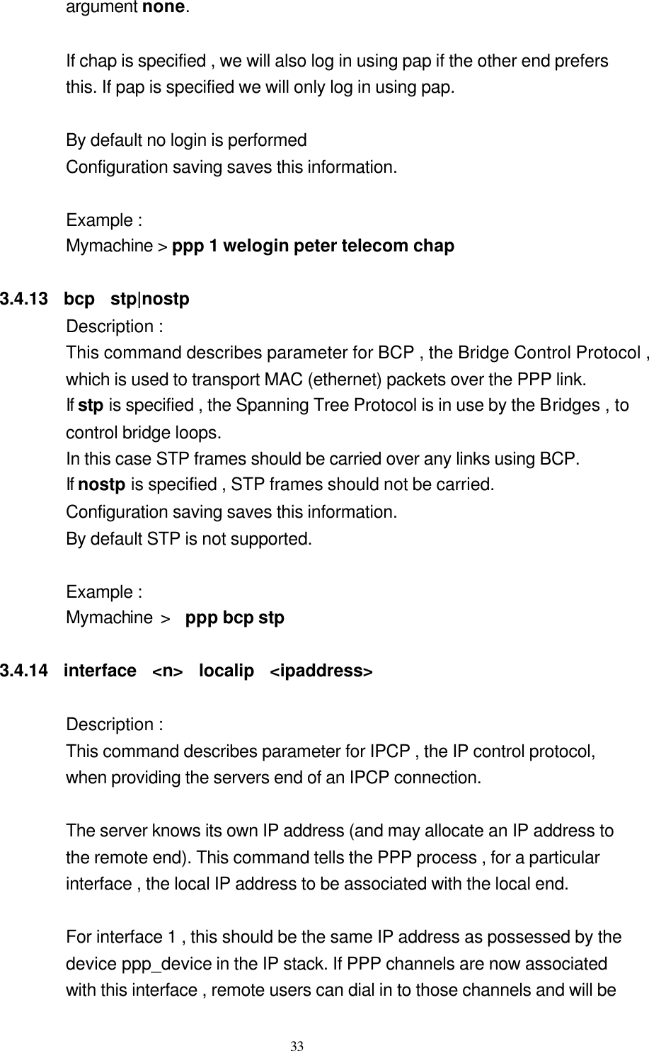
![32 This command specifies that when using this channel , the user must log on using the specified protocol , and that they must provide any name/password combination which has been defined for that protocols , using the user command . To remove this information on a channel , call theylogin with a single argument of none. By default no login is required. Configuration saving saves this information Example : see remoteip 3.4.11 <channel> tunnel <n> <tunnel protocol> <dial direction> Description : Logically associated the specified channel with the specified tunnel. A single PPP channel can only be associated with a single interface ,or a single tunnel. Use info to find the current setting. Calling with n=0 removes any association . This is the default state. The possible tunnel protocols are : pptp and l2tp. The dial direction may be : in or out for dial-in or dial-out respectively. Configuration saving saves this information. Example : Mymachine : ppp 3 tunnel 1 pptp out 3.4.12 <channel> welogin <name> <password> [pap|chap] Description : This command describes how we should login to the far end when a connection is established. A name and password are supplied , and whether these should be used with the PAP or CHAP authentication protocol . CHAP is the default. To remove this information on a channel , call welogin with a single](https://usermanual.wiki/UAT/AR-5153/User-Guide-139285-Page-32.png)
![34 connected to the IP stack. They can be allocated IP address , see the command <channel> remoteip. Call with 0.0.0.0 to remove any IP address setting . This is the default state. Configuration saving saves this information. Example : Mymachine > ppp interface 1 localip 192.168.1.1 3.4.15 interface <n> stats Description ; The interface is regarded by the operating system as an Ethernet-like device which can be attached to the bridge or router. It also provides an ifEntry to SNMP providing basic information about traffic through the interface. This command shows the basic information about byte and package traffic through the interface , in SNMP terms. Example : Mymachine > ppp interface 1 stats 3.4.16 user add <name> [pwd <passwd> [pap | chap] ] user [ <name >] user delete <name>| all Description : This command stores information about a particular login name /password combination. Use user delete to delete an individual user by name , or to delete all users. Use user add to create a new user or update an existing one.](https://usermanual.wiki/UAT/AR-5153/User-Guide-139285-Page-34.png)
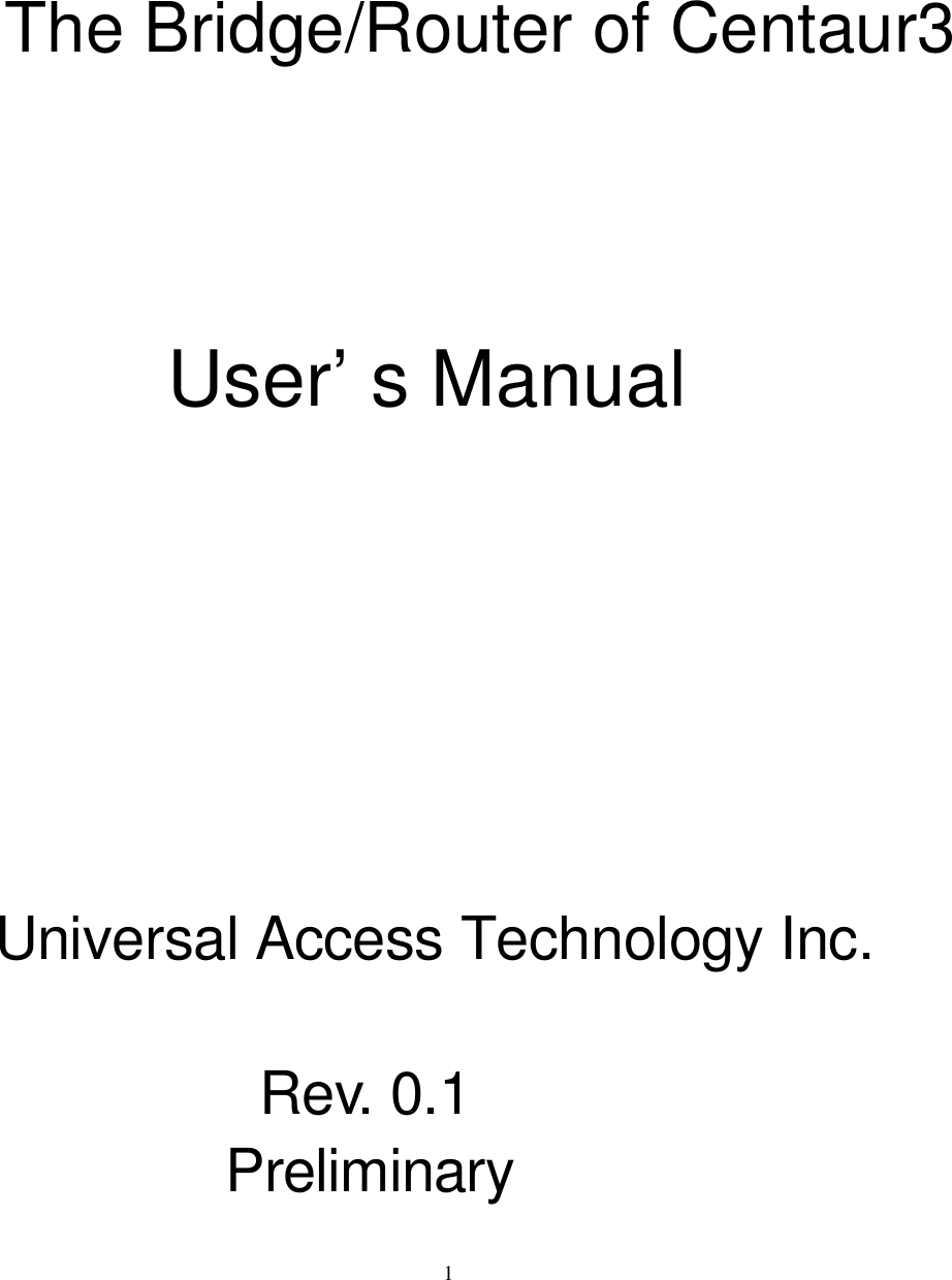
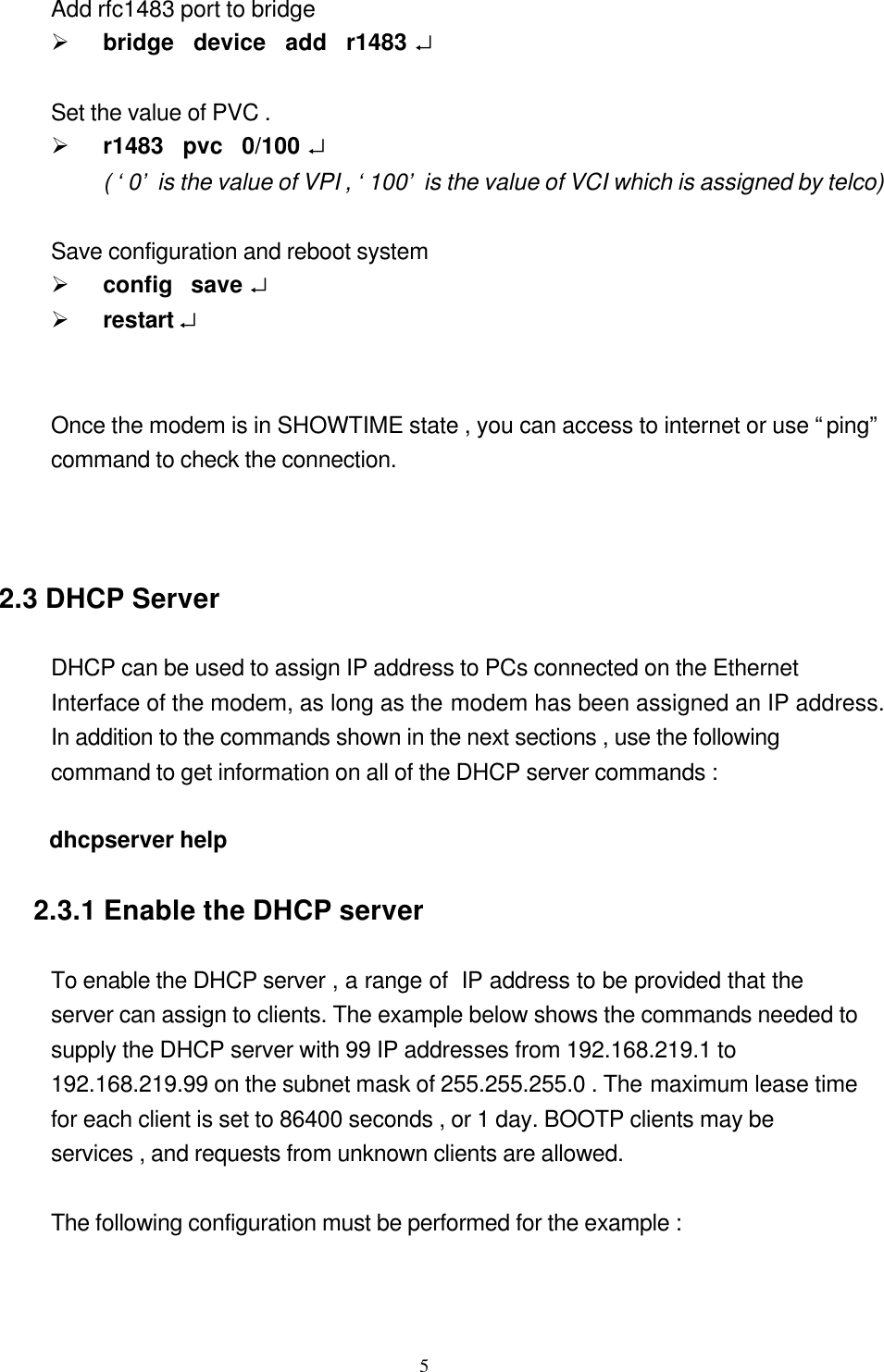
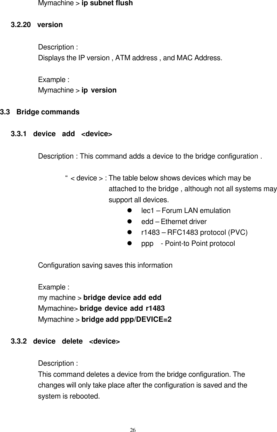
![38 3.6.3 pvc pvc x/y Description: This command sets and displays the PVC used for communication . When setting the PVC , the configuration must be saved And the system restarted before the changes takes effect.. “ x “ is VPI and “ y” is VCI. Normally , VPI is 0 and VCI is in the range 0~1023. 3.6.4 ststus Description ; This command displays the status of the RFC1483 process .At present , the status consists of whether the process is active , that is has a valid PVC , or is inactive , that is has no PVC. Example : Mymachine > r1483 status Example : Mymachine > r1483 pvc Mymachine > r1483 pvc 0/100 3.7 dhcpserver commands 3.7.1 config [add <text> | confirm | delete | flush] Description : This command displays or edits the current configuration of the DHCP server . To display current configuration , provide no argument to the command. Use of the “add” argument adds the line <text> to the configuration file.](https://usermanual.wiki/UAT/AR-5153/User-Guide-139285-Page-38.png)