UBS Axcera 420A Low Power Television User Manual Chapter 3
UBS-Axcera Low Power Television Chapter 3
Contents
Chapter 3

100 Watt High Band VHF Transmitter Chapter 3, Installation and Setup Procedures
420A, Rev. 0 3-1
Chapter 3
Installation and Setup Procedures
There are special considerations that
need to be taken into account before the
420A transmitter can be installed. For
example, if the installation is completed
during cool weather, a heat-related
problem may not surface for many
months, suddenly appearing during the
heat of summer. This section provides
information that will assist in planning for
the installation and set up of the
transmitter.
3.1 Site Considerations
The transmitter requires an AC input line
of 115 or 230 VAC with a rating of 10
amps. Make sure that the proposed site
for the transmitter has the voltage
requirements that are needed.
The 420A is designed and built to provide
long life with a minimum of maintenance.
The environment in which it is placed is
important and certain precautions must
be taken. The three greatest dangers to
the transmitter are heat, dirt, and
moisture. Heat is usually the greatest
problem, followed by dirt, and then
moisture. Overtemperature can cause
heat-related problems such as thermal
runaway and component failure. Each
amplifier tray in the transmitter contains
a thermal interlock protection circuit that
will shut down that tray until the
temperature drops to an acceptable level.
A suitable environment for the
transmitter can enhance its overall
performance and reliability and maximize
revenues by minimizing down time. A
properly designed facility will have an
adequate supply of cool, clean air, free of
airborne particulates of any kind, and
without excessive humidity. An ideal
environment requires temperatures in
the range of 40° F to 70° F throughout
the year, reasonably low humidity, and a
dust-free room. It should be noted that
this is rarely if ever attainable in the real
world. However, the closer your
environment is to this design, the greater
the operating capacity of the transmitter.
Although the fans and blowers designed
and built into the transmitter will remove
the heat from within the cabinet,
additional means are required for
removing heat from the building. To
achieve this, a few considerations should
be taken into account. The first step is to
determine the amount of heat to be
removed. There are generally three
sources of heat that must be considered.
The first and most obvious is the heat
from the 100-watt transmitter itself. This
can be determined by subtracting the
average power to the antenna (69.5
watts) from the input power (750 watts).
This number in watts (680.5) is then
multiplied by 3.41, which gives 2320, the
BTUs to be removed every hour.
The second source of heat is other
equipment in the same room. This
number is calculated in the same way as
the equation for BTUs. The third source
of heat is equally obvious but not as
simple to calculate. This is the heat
coming through the walls, roof, and
windows on a hot summer day. Unless
the underside is exposed, the floor is
usually not a problem. Determining this
number is usually best left up to a
qualified HVAC technician. There are far
too many variables to even estimate this
number without detailed drawings of the
site showing all construction details. The
sum of these three sources is the total
amount of heat that must be removed.
There may be other sources of heat, such
as personnel, and all should be taken into
account.
Now that the amount of heat that must
be removed is known, the next step is to
determine how to accomplish this. The

100 Watt High Band VHF Transmitter Chapter 3, Installation and Setup Procedures
420A, Rev. 0 3-2
options are air conditioning, ventilation,
or a combination of the two. Air
conditioning is always the preferred
method and is the only way to create
anything close to an ideal environment.
Ventilation will work if the ambient air
temperature is below 100° F, or about
38° C, and the humidity is kept at a
reasonable level. In addition, the air
must be adequately filtered to ensure
that no airborne particulates of any kind
will be carried into the transmitter. A
combination of air conditioning for
summer and ventilation during the cooler
months is acceptable when the proper
cooling cannot be obtained through the
use of ventilation alone and using air
conditioning throughout the year is not
feasible.
Caution: The operation of air
conditioning and ventilation
simultaneously is not recommended.
This can cause condensation in
transmitters. For tube type
transmitters, this can be especially
serious if the condensation forms in
the tube cavity and creates
damaging arcs.
The following precautions should be
observed regarding air conditioning
systems:
1. Air conditioners have an ARI
nominal cooling capacity rating. In
selecting an air conditioner, do not
assume that this number can be
equated to the requirements of
the site. Make certain that the
contractor uses the actual
conditions that are to be
maintained at the site in
determining the size of the unit.
With the desired conditioned room
temperature under 80° F, the unit
must be derated, possibly by a
substantial amount.
2. Do not have the air conditioner
blowing directly onto the
transmitter. Under certain
conditions, condensation may
occur on, or worse in, the
transmitter.
3. Do not isolate the front of the
transmitter from the back with the
thought of air conditioning only
the front of the unit. Cooling air is
drawn in at the front of all
transmitters and in the front and
back of others. Any attempt to
isolate the front of the transmitter
from the rear of the unit will
adversely affect the cooling air
flow.
4. Interlocking the transmitter with
the air conditioner is
recommended to keep the
transmitter from operating without
the necessary cooling.
5. The periodic cleaning of all filters
is a must.
When using ventilation alone, the
following general statements apply:
1. The blower, with attendant filters,
should be on the inlet, thereby
pressurizing the room and
preventing the ingress of dirt.
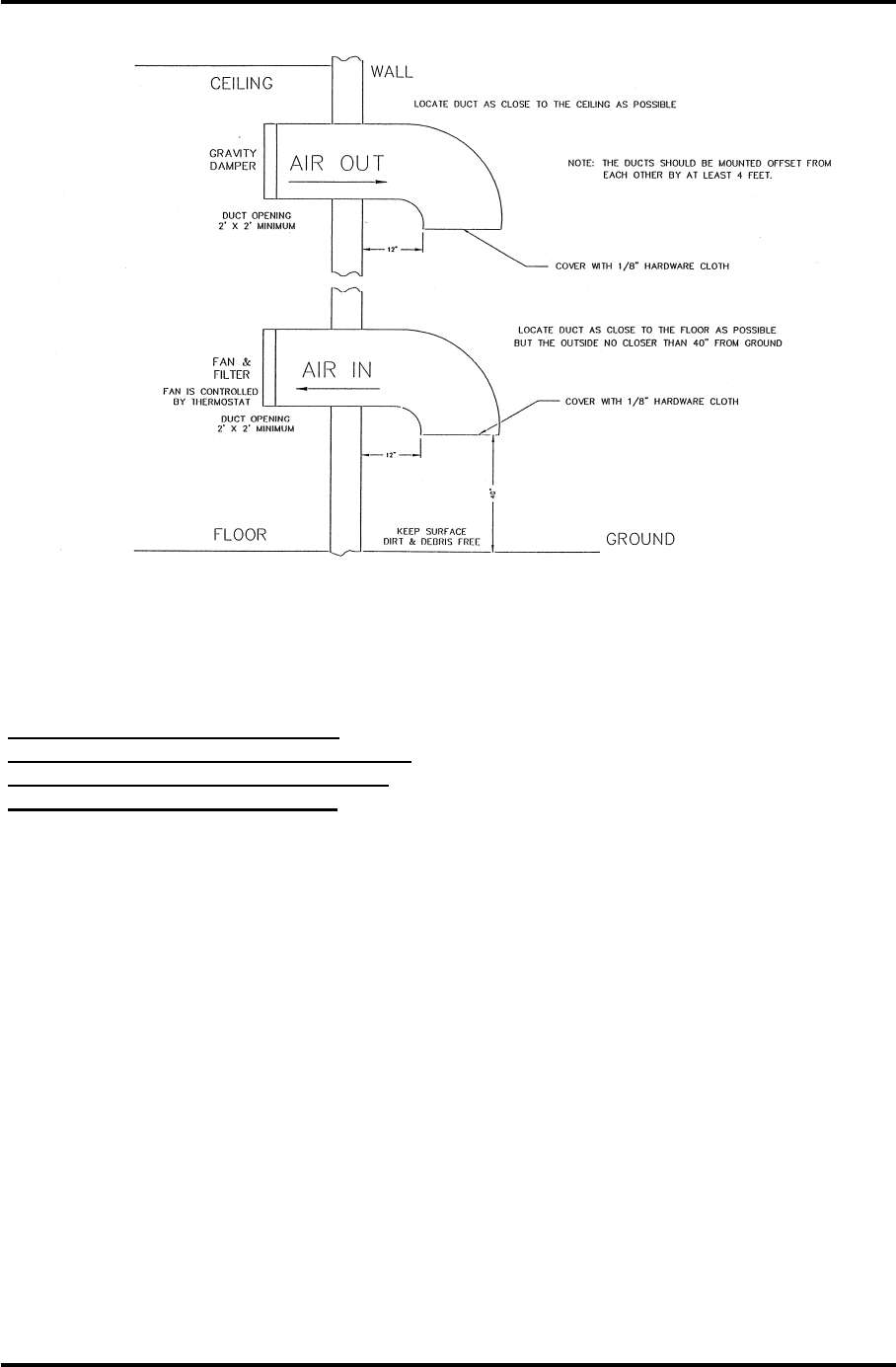
2. The inlet and outlet vents should
be on the same side of the
building, preferably the leeward
side. As a result, the pressure
differential created by wind will be
minimized. Only the outlet vent
may be released through the roof.
3. The inlet and outlet vents should
be screened with 1/8" hardware
cloth (preferred) or galvanized
hardware cloth (acceptable).
4. Cooling air should enter the room
as low as practical but in no case
higher than four feet above the
floor. The inlet must be located
where dirt, leaves, snow, etc., will
not be carried in with the cooling
air.

100 Watt High Band VHF Transmitter Chapter 3, Installation and Setup Procedures
420A, Rev. 0 3-3
5. The exhaust should be located as
high as possible. Some ducting is
usually required to insure the
complete flushing of heated air
with no stagnant areas.
6. The filter area must be adequate
to insure a maximum air velocity
of 300 feet per minute through the
filter. This is not a conservative
number but a never-exceed
number. In a dusty or remote
location, this number should be
reduced to 150 CFM.
7. The inlet and outlet(s) must have
automatic dampers that close any
time the ventilation blower is off.
8. In those cases in which
transmitters are regularly off for a
portion of each day, a
temperature-differential sensor
that controls a small heater must
be installed. This sensor will
monitor inside and outside
temperatures simultaneously. If
the inside temperature falls to
within 5° F of the outside
temperature, the heater will come
on. This will prevent condensation
when the ventilation blower comes
on and applies even in the
summer.
9. A controlled-air bypass system
must be installed to prevent the
temperature in the room from
falling below 40° F during
transmitter operation.
10. The blower should have two
speeds that are thermostatically
controlled and interlocked with the
transmitter.
11. The blower on high speed must be
capable of moving the required
volume of air into a half inch of
water pressure at the required
elevation. The free air delivery
method must not be used.
12. Regular maintenance, cleaning,
and/or replacement of the filters
can not be overemphasized.
13. It is recommended that a site plan
be submitted to ADC
Telecommunications for comment
before installation commences.
The information presented in this section
is intended to serve only as a general
guide and may need to be modified for
unusually severe conditions. A
combination of air conditioning and
ventilation should not be difficult to
design (see Figure 3-1). System
interlocking and thermostat settings
should be reviewed with ADC
Telecommunications. As with any
equipment installation, it is always good
practice to consult the manufacturer
when questions arise. ADC
Telecommunications can be contacted at
(724) 941-1500.
100 Watt High Band VHF Transmitter Chapter 3, Installation and Setup Procedures
420A, Rev. 0 3-4
Figure 3-1. 1 kW Minimum Ventilation Configuration
3.2 Unpacking the Cabinets and
Trays
Note: Air conditioning and any
related heat exhaust ducts should be
in place before continuing with the
installation of the transmitter.
Thoroughly inspect the cabinet (if
provided), 100-watt tray, and all other
shipped material upon their arrival. ADC
Telecommunications certifies that upon
leaving our facility the equipment was
undamaged and in proper working order.
The shipping containers should be
inspected for obvious damage that is
indicative of rough handling. Check for
dents and scratches or broken switches,
meters, or connectors. Any claims
against in-transit damage should be
directed to the carrier. Inform ADC
Telecommunications as to the extent of
any damage as soon as possible.
Remove the cabinet (if provided) and the
100-watt tray, as well as any installation
materials that make up the 420A, from
the crates and boxes. Remove the straps
that hold the cabinet to the shipping skid
and slide the cabinet from the skid.
Remove the plastic wrap and foam
protection from around the cabinet. Do
not remove any labeling or tags from the
cabinet as well as any cables or
connectors. These are identification
markers which make reassembly of the
transmitter much easier.
100 Watt High Band VHF Transmitter Chapter 3, Installation and Setup Procedures
420A, Rev. 0 3-5
3.3 Installation of the Trays Not
Supplied With a Cabinet
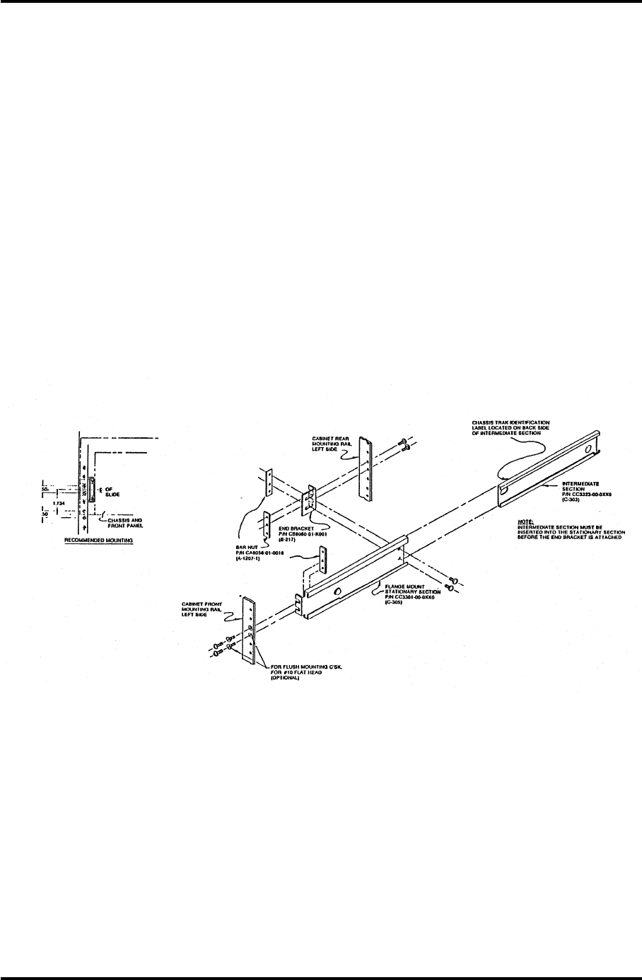
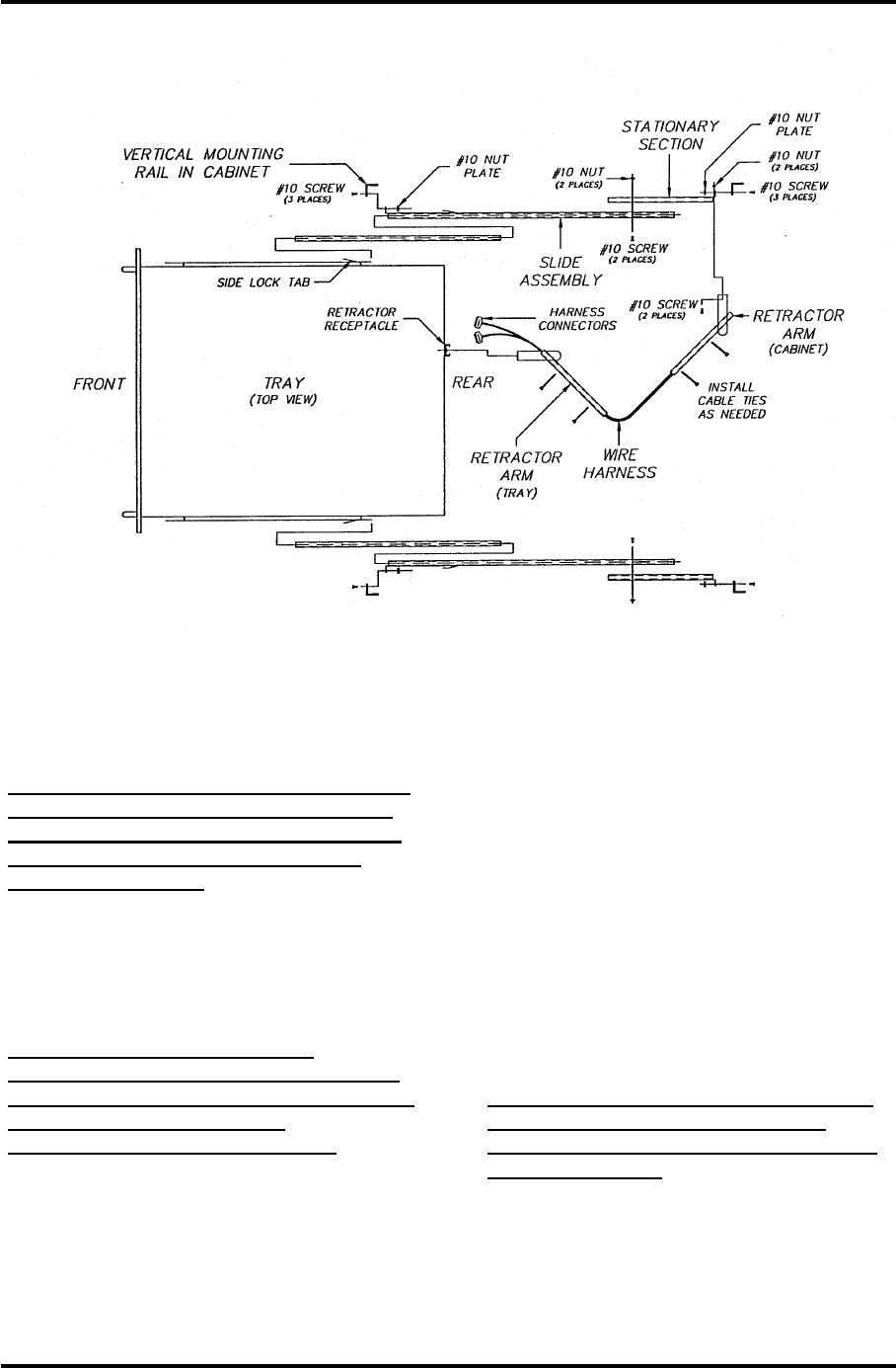
The trays are to be mounted in a
standard 19" cabinet using Chassis Trak
cabinet slides (see Figure 3-2). The side
rails are pre-mounted on the sides of the
trays. Install the tray slides found in the
installation materials into the left and
right side of a standard 19" cabinet, as
shown in Figure 3-3. Check that the tray
slides are mounted in line with each
other. Secure the slides by connecting
them to the front and rear mounting bars
by using the No. 10 bolts and bar nuts
that have been provided. Insert the
tray(s) onto the tray slides and slide the
tray(s) into the cabinet. Slowly slide each
tray in and out to verify that they do not
rub against each other and have no
restrictions to free movement.
Adjustments to the position of the trays
may be necessary. This can be
accomplished by loosening the cabinet
slide mounting bolts that hold the front of
the slide to the mounting frame of the
cabinet and moving the tray up or down
as needed to correct for the rubbing.
Retighten the bolts after making any
adjustments. If multiple transmitters are
purchased, refer to the tray layout
drawing for that specific system for the
proper position of each tray.
Figure 3-2. Chassis Trak Cabinet Slides
100 Watt High Band VHF Transmitter Chapter 3, Installation and Setup Procedures
420A, Rev. 0 3-6
Figure 3-3. Cabinet Mounting Diagram
Connect the baseband video input to J2
on the rear of the tray.
Note: J2 is a loop-through connected
to J1. It can be used as a baseband
video source if the jumper W1 on J3
of the sync tip clamp/modulator
board is removed.
Connect the baseband balanced audio to
the terminal block (TB1) or connect the
composite audio (stereo) to the BNC jack
(J13).
NOTE: J13 is a loop-through
connected to J3. It can be used as a
composite audio source if the jumper
W4 on J12 of the aural IF
synthesizer board is removed.
Connect the transmission line of the
antenna to the bandpass filter assembly
output A2-A2-J2.
If the remote power raise/lower kit
(1227-1039) is purchased, the external
power raise/lower control connects to
jack (J10), a 25-position, "D"-type
connector, on the rear of the tray. Other
remote control functions also connect to
J10 and J11 of the transmitter. The
remote power raise/lower switch
connects to the J10 jack at J10-11 power
raise, J10-13 power raise/lower return,
and J10-12 power lower.
Connect the AC line cord into jack (J14)
on the rear of the tray. Connect the other
end of the AC line cord into an AC outlet
capable of supplying at least 10 amps of
current.
Note: If the incoming AC requires a
reconfiguration, see Chapter 2,
System Description, for information
on the AC input.
This completes the unpacking and
installation procedures for the 420A.
Refer to the system setup and operation
procedures which follow before applying
power to the transmitter.

100 Watt High Band VHF Transmitter Chapter 3, Installation and Setup Procedures
420A, Rev. 0 3-7
3.4 Setup and Operation Procedures
Initially, the transmitter should be turned
on with the RF output at the bandpass
filter asssembly terminated into a
dummy load with a rating of at least 100
watts. If a load is not available, check
that the output is connected to the
antenna.
Connect the baseband video or the
(optional) 4.5 MHz composite input to J2
on the rear of the tray.
Note: J2 is a loop-through connected
to J1. It can be used as a baseband
video source if the jumper W1 on J3
of the sync tip clamp\modulator
board is removed.
Connect the baseband audio, if it is
balanced audio, to the terminal block
(TB1) or connect the composite audio
(stereo) to the BNC jack (J13).
Note: J13 is a loop-through
connected to J3. It can be used as a
composite audio source if the jumper
W4 on J12 of the aural IF
synthesizer board is removed.
Note: To operate using the baseband
video input with the (optional) 4.5
MHz composite input kit, the
baseband select must be present at
J18-6 and 7 on the rear of the tray.
To operate using the 4.5 MHz
composite input, the baseband select
must be removed from J18-6 and 7
on the rear of the tray.
Switch on the AC circuit breaker CB1 on
the rear of the tray. Switch the
Operate/Standby switch to Standby and
the Auto/Manual switch to Manual.
Normal operation of the transmitter is in
Automatic and the video input to the
transmitter is used as an
Operate/Standby switch. In Auto, if the
input video is lost, the transmitter will
automatically revert to Standby. When
the video signal is restored, the
transmitter will automatically return to
Operate.
Move the Operate/Standby switch,
located on the front of the tray, to
Operate.
Note: If the transmitter does not
switch to Operate when the
Operate/Standby switch is switched
to Operate, check that the external
interlock plug, with a jumper from
pins 23 to 24, system interlock, is
connected to jack (J11) on the rear
of the tray.
Observe the % Visual Power reading on
the front panel meter; it should read
100%. If needed, set the power adjust
pot located on the front panel. As you are
checking the power level, also check the
meter reading in the % Reflected Power
position. If the % Reflected Power is very
high, above 20%, a problem with the
output coaxial line is present and needs
to be checked. Return the
Operate/Standby switch to Standby.
If a dummy load is connected to the
transmitter, switch off the on/off AC
circuit breaker on the rear of the 100-
watt tray. Remove the dummy load and
make all connections needed to connect
the transmitter to the antenna. Switch
the AC circuit breaker on and the
Operate/Standby switch to Operate.
Adjust the output power front panel
adjustment to attain 100% output.
Return the Operate/Standby switch to
Standby.
This completes the setup and operation
procedures for the 420A transmitter.
If a problem occurred during the setup
and operation procedures, refer to
Chapter 4, Detailed Alignment
Procedures, of this manual for more
information concerning specific trays.