UBS Axcera 5543A 8-Watt BRS/EBS Digital Frequency Agile Transmitter User Manual 5543a title page

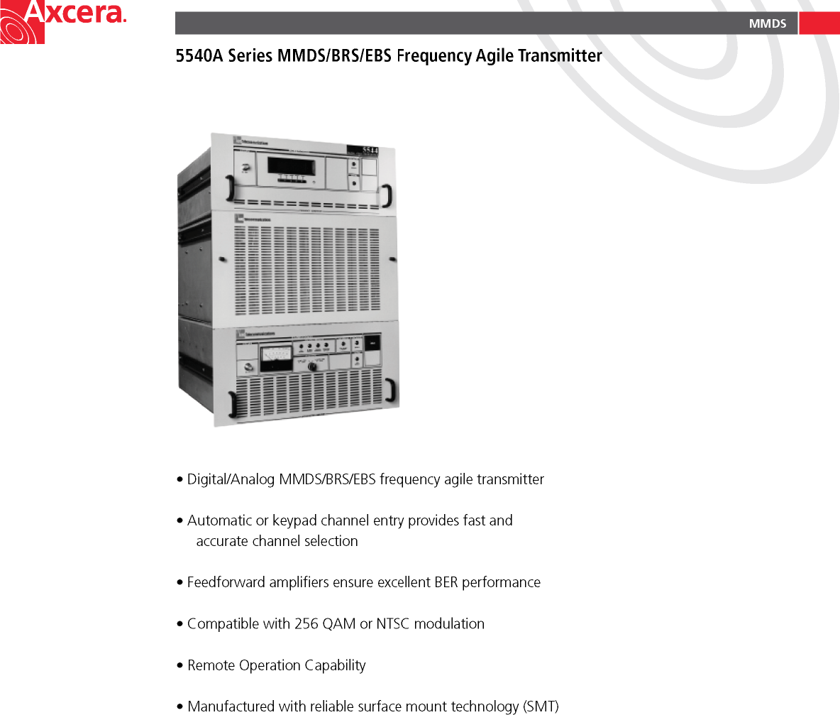
UBS-Axcera 8-Watt BRS/EBS Digital Frequency Agile Transmitter 5543a title page

Compiled User Manual 5543A

     OPERATION MANUAL                  5543A DIGITAL AGILE TRANSMITTER                AXCERA, LLC  103 FREEDOM DRIVE P.O. BOX 525  LAWRENCE, PA 15055-0525 USA (724) 873-8100 • FAX (724) 873-8105 www.axcera.com • info@axcera.com
SYSTEM 5543A DIGITAL AGILE  PAGE 1   INSTALLATION PROCEDURE    UNPACKING  Please inspect all material thoroughly upon arrival. Axcera certifies that upon leaving our facility the equipment was undamaged and in proper working order.  The shipping container should be inspected for obvious damage indicative of rough handling.  Remove the unit(s) from the shipping container and inspect for damage.  Check for dents, and scratches, or a broken switch, meter or connector.  Remove the top cover of the unit and again inspect for shipping damage. Extract all packing material from inside and around the unit. Check for loose hardware and connectors, retighten if needed. Any claims against in-transit damage should be directed to the carrier.  Save all packing  material in case it is needed in the future.  INSTALLATION OF TRAY(S)   í Units are shipped with chassis slides mounted to the each side.  Included in the Installation Material Kit are two cabinet mount slide assemblies that will be mounted in the rack.  Install the Tray slides into the cabinet.  Refer to the "Cabinet Mounting Instructions Slides Drawing" which follows, for detailed instructions.  í Slide the unit into the cabinet.  If it does not slide in and out smoothly, some adjustment is necessary.  Pull out the unit (only enough for clearance) and loosen the hardware holding the cable slides to the cabinet.  Move the front of the Tray up or down or side to side to remove the rubbing.  Retighten the hardware after the adjustment is complete.  í Also included with the unit is a cable retractor assembly, which consists of two parts, a cabinet mount retractor and a tray mount retractor.   n The cabinet mount retractor has a long aluminum channel hinged to a mounting piece with two bolts.  This is mounted to the rear of the left hand, facing the front of the unit, cabinet mount slide assembly.    n The retractor is a short aluminum channel hinged to a slide mount.  This piece slides into a receptacle mounted to the rear panel of the unit.  These cable retractors work together to move the wire harness and coaxial cables in and out with the movement of the unit to avoid pinched wires.   í After the units(s) are physically in place, the process of interfacing them into the system begins  by making connections to the back of the units.
SYSTEM 5543A DIGITAL AGILE  PAGE 2    CABINET MOUNTING INSTRUCTIONS FOR SLIDES DRAWING    CONNECTIONS  Once all equipment is in place, making connection to the back of the tray (s) is a relatively simple process. Each wire is clearly marked with a number corresponding to the tray where it connects.  NUMBERING  The numbering system used on wires that connect to the back of the trays is as follows:   FIRST NUMBER - Channel designator  SECOND NUMBER - Connector on back of tray  EXAMPLE: A wire marked   2    10  would go to channel 2 in the group, connector J10  Finally, verify that AC power (J1) is connected to each unit. Once this is complete, proceed to the initial turn on procedures.   NOTE: All  Axcera products are designed for operation with either 115VAC or 208/230 VAC, 50/60 Hz input.  Systems are shipped from the factory properly configured for the standard of the country of destination.
SYSTEM 5543A DIGITAL AGILE  PAGE 3   SYSTEM DESCRIPTION   FREQUENCY GENERATOR TRAY  The Frequency Generator tray is configured to control multiple VCXO’s. within the 4 Channel VCXO assembly. The selected VCXO output is sent to the VHF Buffer/Combiner Board where the RF signal is amplified. The output of the VHF Buffer/Combiner Board  is multiplied by four and filtered, then processed by the PLL Board. Once again the signal is multiplied and filtered producing an L.O. output to the agile upconverter. A liquid crystal display on the front panel provides access to various menus through the use of five soft touch keys.      10-WATT AGILE UPCONVERTER/AMPLIFIER  The 10-Watt Agile Upconverter/Amplifier accepts an input signal of  +25 to  +35 dBmV and is compatible with any QAM signal up to 256 and VSB up to 16.  Operating frequency range is from 2572-2614 MHz. The signal is processed through the unit in a similar manner to that of an analog system with IF circuitry performing ALC, frequency response and delay correction as well as linearity correction.  The RF signal is sampled, peak detected, and fed to a control amplifier before being connected to the output of the tray.
INITIAL TURN ON 5543A DIGITAL AGILE  PAGE 4   INITIAL TURN ON Prior to turning on the system, be sure all connections are in the correct place, and AC power is connected to the back of each tray. Next, follow the steps below:  í Turn on each circuit breaker (CB1) located on the back of each unit beginning with the AC Distribution Panel.  í Verify that each unit is in standby mode. Upon initial turn on, the following LED indicators should be on.    FREQUENCY GENERATOR - Operate and fault LED should flash twice and then go off.  UPCONVERTER.AMPLIFIER -PLL LOCKED -IF INPUT PRESENT -THERMAL INTERLOCK -EXTERNAL 10 MHz PRESENT (optional)   í After verifying that each unit is in standby mode and that the initial turn on LED indicators are on, press the OPR softkey located on the front of the Frequency Generator Tray. The following additional indicators should light:           FREQUENCY GENERATOR -OPERATE  UPCONVERTER/AMPLIFIER -ENABLE -SWITCHING SUPPLIES    í IN THE EVENT ANY RED LED’s ARE ON, RETURN THE UNIT TO STANDBY MODE AND CONTACT AXCERA SERVICE IMMEDIATELY.
OPERATION 5543A DIGITAL AGILE  PAGE 5  UNIT OPERATION  Located on the front of the Frequency Generator Tray are soft-keys and a liquid crystal display. Four menu screens are available: status, mode, fault, and channel setup.  Initially when the unit is turned on, a title screen appears which displays the company logo, address, and phone number.  Next, the status screen appears as follows:                      The first line displays the status of the system. To change from standby to operate, press the OPR button. The unit will switch to operate mode. Displayed on the second line is the channel the frequency generator is tuned to. To scroll through the channels press the DWN or the UP key. The channel menu is only available in standby mode.  From the status screen press the NXT key. The display will then read as follows:                      This menu allows easy switching from manual to automatic mode. In order to make any changes in channel setup, the unit must be in manual mode. Automatic mode runs through a continuos loop checking for faults  detected by the ABS (Automatic Backup System), which will detect any problems and send the appropriate information to the Frequency Generator.  Once again, press the NXT key. This will access the fault menu:                      Displayed on the first line is the total number of faults (if any) and a specific list of the particular fault (s). Scroll through the list by using the DWN and UP key. The CLR key is used to clear the fault from the display, but if the fault condition remains, the message will return.  Finally, a channel setup is available. The unit must be in standby to make any changes.                      The UP and DWN key will scroll through the available channels and indicate if that particular channel is available or unavailable. Press the UNAV key to change which channels are available and unavailable.  STATUS: STANDBY CHANNEL : A1  MANUAL MODE PRV DWN UP OPR NXT MODE SELECT  STATUS : STANDBY MANUAL MODE PRV AUT   NXT FAULTS : 0  NONE  PRV   CLR NXT CHANNEL SETUP CHANNEL : A1   (AVAIL)  PRV DWN UP UNAV NXT
FREQUENCY GENERATOR 5543A DIGITAL AGILE  PAGE 6     FRONT PANEL FREQUENCY GENERATOR TRAY                                          SAMPLE  CH. OSC     Provides a sample from the channel oscillator.   CONTROL   OPERATE     Indicates that the unit is operational   FAULT      Indicates a fault condition   Also included on the front panel is an LCD display with 5 soft-keys below it. The soft-keys allow access to various menus that are explained in the unit operation section of this manual.
FREQUENCY GENERATOR 5543A DIGITAL AGILE  PAGE 7   REAR PANEL FREQUENCY GENERATOR TRAY      LO OUTPUT (J4)    Provides a local oscillator output from the tray  EXT 10 MHz REF I/P (J2)   10 MHz reference input  ABS COMMUNICATIONS (J3)   Accesses Automatic Backup System  REMOTE/CONTROL    Provides remote/control functions  AC (J1)      AC input to the tray  CB1      Circuit breaker protected ON/OFF switch
FREQUENCY GENERATOR 5543A DIGITAL AGILE  PAGE 8     INTERNAL LED INDICATORS FREQUENCY GENERATOR TRAY  ASSEMBLY LED INDICATES PLL BOARD  DS1 RED PLL Unlocked FREQUENCY GENERATOR CONTROL BOARD DS3 RED Fault FREQUENCY GENERATOR CONTROL BOARD DS2 GREEN Unit is in operate mode FREQUENCY GENERATOR CONTROL BOARD DS1 GREEN Activity status indicator which lights when specific commands are received or implemented by the microprocessor.
UPCONVERTER/AMPLIFIER 5543A DIGITAL AGILE  PAGE 9   FRONT PANEL  UPCONVERTER/AMPLIFIER  SAMPLE  1ST L.O.    Provides a sample of the first L.O.  OPERATING STATUS  PLL LOCKED    The unit is phase locked to an internal or external reference          IF INPUT PRESENT   An IF input is present  THERMAL INTERLOCK    A thermal interlock has been achieved  SWITCHING SUPPLIES    Switching power supplies are operational  FREQ REF  EXT 10 MHz PRESENT   An external 10 MHz source is present  CONTROL  ENABLE    Unit is operational  FAULT  LOW OUTPUT    Unit output is low  METERING  % REFL. PWR    Percentage of reflected power. Should be less than 10%.   %  OUTPUT PWR   Output power. Should be < 100%.
UPCONVERTER/AMPLIFIER 5543A DIGITAL AGILE  PAGE 10    REAR PANEL UPCONVERTER/AMPLIFIER    LO I/P (J5)      Provides an L.O. input into the unit.  LO O/P (J6)      L.O. output sample  RF O/P (J10)      RF output from the unit  IF I/P (J2)      IF input to the unit  EXT 10 MHz REF I/P (J3)    10 MHz reference input (source)  EXT 10 MHz REF O/P (J4)    10 MHz reference output (to Freq. Gen)  EXT FWD SAMPLE I/P (J19)    NOT USED  EXT REFL SAMPLE I/P (J18)    NOT USED  AC (J1)       AC input to the unit  CB1       Circuit breaker protected on/off switch  REMOTE/CONTROL     Accesses remote/control features
UPCONVERTER/AMPLIFIER 5543A DIGITAL AGILE  PAGE 11   UPCONVERTER/AMPLIFIER  INTERNAL LED INDICATORS   ASSEMBLY  LED  INDICATES  ALC/AGC BOARD    DS1 RED INPUT FAULT  ALC/AGC BOARD    DS2 RED ALC FAULT  ALC/AGC BOARD    DS3 RED MUTE  ALC/AGC BOARD    DS4 RED AGC FAULT  VHF GENERATOR CONTROL BD     DS1 RED PLL UNLOCKED  BIAS PROTECTION BOARD    DS1-DS7 GREEN NORMAL OPERATING AND BIASING VOLTAGES PRESENT  DC POWER SUPPLY BOARD    DS1-DS7 GREEN CORRECT VOLTAGES PRESENT  TRANSMITTER CONTROL BOARD    DS1 GREEN ENABLED   TRANSMITTER CONTROL BOARD    DS2 GREEN THERMAL INTERLOCK  TRANSMITTER CONTROL BOARD    DS3 GREEN EXT. REFERENCE PRESENT  TRANSMITTER CONTROL BOARD    DS4 GREEN IF PRESENT  TRANSMITTER CONTROL BOARD    DS5 GREEN PLL LOCKED  TRANSMITTER CONTROL BOARD    DS6 RED LOW OUTPUT  TRANSMITTER CONTROL BOARD    DS7-GREEN SWITCHING POWER SUPPLIES GOOD  PEAL VS AVERAGE DETECTOR BOARD     DS1-RED FAULT
MAINTENANCE 5543A DIGITAL AGILE  PAGE 12   MAINTENANCE  PROPER CARE OF THE SYSTEM  This product is designed with components that require no periodic maintenance except for cleaning and record keeping.  The amount of cleaning necessary depends greatly on the conditions in the transmitter room.  While the electronics have been designed to function well even if covered with dust, heavy buildups of dirt and insects will impede the effectiveness of the cooling and lead to shutdown or premature failure.  When it is apparent that the front panel is becoming dust covered, the top cover should be opened and the accumulated foreign material removed.  A small, soft brush used in conjunction with a plastic wand-like attachment on a small vacuum cleaner is an excellent way to suction the dirt out.  Alcohol and other cleaning agents should not be used unless you can be certain that the solvents will not damage components or markings on the transmitter and boards.  Water based cleaners can be used, if only a small amount of moisture is used.  The fans and heatsinks should be cleaned carefully.  Occasionally check that all RF connections are secure, but be careful not to overtighten.  Data should be recorded for all meter readings on a regular basis.  It is suggested that data be recorded once each month and that it be retained in a rugged folder or envelope for the life of the equipment.  TROUBLESHOOTING PROCEDURE  AGILE UPCONVERTER/AMPLIFIER SYMPTOM CAUSE REMEDY FRONT PANEL    VHF PLL LOCKED LED out 1. PLL is unlocked 2. Carrier frequency is out of spec 1. Adjust UHF Generator 2. Call Axcera Customer Service THERMAL INTERLOCK LED out 1. Transmitter has overheated   1. Check Fan  2. Check Air conditioning system EXT 10 MHz PRESENT LED out 1. No 10 MHz signal present 1. Check 10 MHz signal to back of transmitter SWITCHING POWER SUPPLIES LED out 1. Wrong input/output voltages 1. Check AC line input voltage to power supply 2. Check output voltage from power supply (10VDC) 3. Call Axcera Customer Service  IF INPUT PRESENT LED out 1. No input to transmitter 1. Check input level to back of transmitter LOW OUTPUT LED on    1. Call Axcera Customer Service Unit will not go to enable mode 1. Fault in control interface 2. Loss of thermal interlock 1. Check control connector on back of tray (if used) 2. Call Axcera Customer Service REAR PANEL     Fan not running 1. Loss of AC power  2. Obstructions Present 1. Remove any fan obstructions 2. Verify AC power source operational 3. Call Axcera Customer Service
MAINTENANCE 5543A DIGITAL AGILE  PAGE 13   INSIDE TRAY     ALC/AGC Board Red LED(s) on 1. Make note of which LED(s) on (DS1-DS4)  1. Call Axcera Customer Service VHF Generator Control Board RED LED on 1. PLL unlocked 1. Adjust UHF Generator 2. Call Axcera Customer Service Six Section Bias Protection Board Green LED(s) DS1-DS7 off 1. Check fuses F1,F3-F7 1. Call Axcera Customer Service DC Power Supply Board Green LED(s) DS1-DS7 off 1. Correct voltages are not present 1 Call Axcera Customer Service  Transmitter Control Board DS1 Yellow LED on 1. Transmitter is in standby mode 1. Switch to operate mode Transmitter Control Board Green LED(s) DS2-DS8 off 1. Check front panel for transmitter fault or green LED’s off 1. Call Axcera Customer Service Transmitter Control Board Red LED DS7 on 1. Low output 1. Call Axcera Customer Service  FREQUENCY GENERATOR TRAY SYMPTOM CAUSE REMEDY FRONT PANEL    FAULT LED on 1.  System malfunction 2.  Microprocessor error 1. Switch to manual mode 2. Call Axcera Customer Service INSIDE TRAY    Fault 1. Use fault menu to detect errors 1. Call Axcera Customer Service if assistance is required.
MAINTENANCE 5543A DIGITAL AGILE  PAGE 14   ALIGNMENT PROCEDURES  GENERAL:  Due to the complex and delicate nature of this digital equipment, very few adjustments can be made in the field. Do not attempt to make any adjustments without proper test equipment.  REQUIRED TEST EQUIPMENT    •  DVM •  Frequency Counter •  Spectrum Analyzer  For settings other than those covered in this section, a network analyzer and other equipment is required. If you have any questions on how to adjust your system contact Axcera Customer Service.    OSCILLATOR CALIBRATION:  The FCC requires that the transmitter carrier frequency should be checked once each month.  If the carrier is found to be off frequency, the following procedure should be performed.  The data resulting from this procedure should be logged for future reference.  A frequency counter that is capable of 5 x 10⁻⁹ stability and a voltmeter are required.   CALCULATE CENTER CARRIER FREQUENCY.   (FOR FREQUENCY GENERATOR TRAY)   í Measure the VCXO frequency (f(s)) at the BNC connector on the front    panel (10 digits).   í Using a 10 digit calculator, perform the following calculation:   [ 16 x f(s)] + 539 MHz                           (2nd L.O.)      (1st L.O.)     The result should be the desired center carrier frequency, ±500 Hz (Axcera spec.) or ±1000 Hz (FCC spec.)   í In the event the frequency appears to be incorrect, check the agile upconverter  front panel VHF PLL indicator, if it is OFF contact Axcera Customer Service.
MAINTENANCE 5543A DIGITAL AGILE  PAGE 15   UHF GENERATOR BOARD (A15-A1) 1512-1101  ALIGNMENT PROCEDURE   1. Connect the main output from the channel oscillator section of the UHF Generator Board (J1) to a spectrum analyzer, tuned to the crystal frequency and peak the tuning capacitors C6 and C11 for maximum output.  Tune L3 and L2 for maximum output.  The output level should be +5 dBm ±2 dB.    While monitoring with a DVM, maximize each of the following test point voltages by    tuning the broadband multipliers in sequence.   2. TP1:  Tune C32 for maximum (Typical 0.6 VDC).   TP2:  Tune C34 and C38 for maximum (Typical 1.2 VDC).   TP3:  Tune C40 and C44 for maximum (Typical 2.0 VDC).   TP4:  Tune C46 for maximum.   TP4:  Re-peak C38, C40, C44 and C46 (Typical 3.5 VDC).   3. Connect a spectrum analyzer, tuned to 8 times the crystal frequency, to the UHF Generator output (J3).  Monitor the output while peaking the tuning capacitors for maximum output.    4. The output level at J2 should be +15 dBm ±2 dB.   WARNING: Performing step 1 in this procedure may change phase noise of oscillator.
MAINTENANCE 5543A DIGITAL AGILE  PAGE 16    VHF GENERATOR CONTROL BOARD (A14) 1555-1214    ALIGNMENT PROCEDURE    1. Disconnect the PLL reference frequency by removing the plug at J5 and/or J6.   2. Connect a digital volt meter between TP4 (+) and ground (-).  Adjust the manual bias potentiometer (R87) for a reading of -3 VDC at TP4.     3. Connect a frequency counter to J11 to measure the VHF frequency (if frequency adjustments are necessary, call Axcera Customer Service.)   4. Set PLL programming per required channel frequency (See programming chart on following page).   5. Connect an oscilloscope between pin 28 of U2 or TP9 (+) and ground (-).    6. Reconnect the plugs at J5 and/or J6 and minimize the spike amplitude that will be observed on the oscilloscope using the phase detector balance potentiometer R70.
MAINTENANCE 5543A DIGITAL AGILE  PAGE 17    PROGRAMMING CHART FOR VHF GENERATOR CONTROL BOARD FREQUENCY AGILE APPLICATIONS  FORMAT VISUAL IF MHz OSCILLATOR FREQUENCY Fc- L.O. + F IF /8 S1 S2 S3 S4 NTSC 44 72.87500 0100 0100 0100 1001 PAL 36 72.76875 1000 0100 0110 0011
MAINTENANCE 5543A DIGITAL AGILE  PAGE 18    ALC/AGC BOARD  1555-1216    PROCEDURE TO DISABLE/ENABLE ALC & AGC:  1. Apply a QAM IF signal to the upconverter tray and place the unit into OPERATE mode.  Verify that  the output power  meter indicates 100%.  2.   On the 1555-1216 ALC/AGC board, move jumper on J11 from AGC to MAN and adjust R105 for  100%, if necessary.  3.   Move jumper on J4 from ALC to MAN and adjust R25 for 100%, if necessary.  4.   To return the transmitter to normal automatic operation, move the two jumpers on the ALC/AGC  board in the upconverter back to the ALC and AGC positions.
MAINTENANCE 5543A DIGITAL AGILE  PAGE 19   PLL BOARD 1527-1402    ALIGNMENT PROCEDURE  1.  Disconnect the PLL reference by removing the plug at J1.  2.  Move jumper W1 to setup position . 3.  Connect a digital voltmeter between TP4 (+) and ground (-). Adjust the VCXO set-up bias potentiometer  R39 for a reading of -3.3VDC at TP4.  4.    Connect a frequency counter to J5 located on the front panel of the frequency generator tray.  5.     Measure the VHF frequency. (if frequency adjustments are necessary call Axcera Customer Service.   6.     Set PLL programming as per required channel frequency (see programming chart on schematic)  7. Return jumper W1 to normal position.
MAINTENANCE 5543A DIGITAL AGILE  PAGE 20   FREQUENCY GENERATOR CONTROL BOARD 1527-1401     ALIGNMENT PROCEDURE  1.  In the event of a microprocessor failure, and that a manual backup is required, move jumper J13 to the manual position.  2.  Set S1-S8 according to the programming chart on the following page. In automatic mode all switches should be set at 1. (1 = off)
MAINTENANCE 5543A DIGITAL AGILE  PAGE 21   OSCILLATOR GATING CHART FOR FREQUENCY GENERATOR BOARD  CH. S1 S2 S3 S4 S5 S6 S7 S8 A4 0000 0000 0010 0000 0000 0000 0000 0000 B4 0000 0000 0000 0010 0000 0000 0000 0000 C4 0000 0000 0001 0000 0000 0000 0000 0000 D4 0000 0000 0000 0001 0000 0000 0000 0000 G4 0000 0000 0000 0000 1000 0000 0000 0000 F4 0000 0000 0000 0000 0000 1000 0000 0000 E4 0000 0000 0000 0000 0100 0000 0000 0000  NOTE:  ON=0 OFF=1. FOR AUTOMATIC MODE SET ALL SWITCHES TO “OFF” = 1
MAINTENANCE 5543A DIGITAL AGILE PAGE 22   )MATERIAL RETURN PROCEDURE   In order to efficiently handle equipment or components returned for repair or sent out on loan, Axcera requests that each returned item be accompanied by a Return Material Authorization Number (RMA#).  To obtain an RMA follow the procedures below:   p Call Axcera Customer Service at (724) 873-8100   or FAX (724) 873-8105   p A Service Engineer will provide you with an RMA#   p Write the RMA# on the packing list or in the case of repairs, a    note describing the reason for return. Also, be sure to include contact   information.   p Send ALL  RMA items to the following address  AXCERA, LLC 103 FREEDOM DRIVE P.O. BOX 525 LAWRENCE, PA 15055-0525   % TELEPHONE TECHNICAL SUPPORT  Axcera currently provides free telephone technical support. When calling, be prepared to provide the following information:   p Transmitter model # AND Serial #   p Status of front panel LED’s (are any red LED’s on ?)   p Have a copy of your operation manual ready prior to calling  From 8:00 AM - 5:00 PM EST call  (724) 873-8100 for technical support
MAINTENANCE 5543A DIGITAL AGILE  PAGE 23   .PROPER PACKING OF MATERIALS   When returning materials to Axcera, it is extremely important to pack them properly. Due to the delicate nature of components contained within the equipment, major damage can occur without proper packing. Please adhere to the following guidelines when returning materials.    o Save the boxes in which the transmitter was shipped. Each tray is sent double boxed and enclosed in foam padding. Use the same packing method when returning materials.   o In the event original packing materials are not available call Axcera at  (724) 873-8100 to request proper shipping materials.  The necessary items will be sent out immediately.     Failure to properly pack any returned materials may result in damage to the equipment. Axcera is not responsible for damaged equipment under these circumstances. Many freight companies will not compensate for damages when items are not packed properly. Please pack items properly!
REFERENCE 5543A DIGITAL AGILE PAGE 24      LIMITED WARRANTY  ONE YEAR  Seller warrants each new product manufactured and sold by Seller against defects in material and workmanship under normal use and service, for a period of one (1) year from the date of shipment from Seller's plant, when operated in accordance with Seller's operating instructions.  This warranty shall not apply to tubes, fuses, batteries, or bulbs.  Warranties are valid only when and if (a) Seller receives prompt written notice of breach within the period of warranty, (b) the defective product is properly packed and returned by the Buyer (transportation and insurance prepaid), and (c) Seller determines, in its sole judgment, that the product is defective and not subject to any misuse, neglect, improper installation, negligence, accident, or (unless authorized in writing by Seller) repair or alteration.  Seller's exclusive liability for any personal and/or property damage (including direct, consequential or incidental) caused by the breach of any or all warranties, shall be limited to the following:  (a) repairing or replacing (in Seller's sole discretion) any defective parts free of charge (F.O.B. Seller's plant), and/or (b) crediting (in Seller's sole discretion) all or a portion of the purchase price to the Buyer.  Equipment furnished by Seller, but not bearing its trade name, shall bear no warranties other than the special hours-of-use or other warranties extended by or enforceable against the manufacturer at the time of delivery to the buyer.  NO WARRANTIES, WHETHER STATUTORY, EXPRESSED OR IMPLIED, AND NO WARRANTIES OF MERCHANTABILITY, FITNESS FOR ANY PARTICULAR PURPOSE, OR FREEDOM FROM INFRINGEMENT, OR THE LIKE, OTHER THAN AS SPECIFIED IN PATENT LIABILITY ARTICLES, AND IN THIS ARTICLE, SHALL APPLY TO THE EQUIPMENT FURNISHED HEREUNDER.                                AXCERA LLC • 103 FREEDOM DRIVE, P.O. BOX 525, LAWRENCE, PA 15055 USA • 724-873-8100 • FAX 724-873-8105
REFERENCE 5543A DIGITAL AGILE PAGE 25    ABREVIATIONS/ACRONYMS  A/D    Analog to digital   SNR    Signal to Noise Ratio  AC    Alternating Current    VCXO    Voltage Controlled Crystal Oscillator  ALC    Automatic Level Control    VSB    Vestigial Sideband  AM    Amplitude modulation  AGC    Automatic Gain Control  AWG    American wire gauge  BER    Bit Error Rate  DC    Direct Current  D/A    Digital to analog  dB    Decibel  dBm    Decibel referenced to 1 milliwatt  dBmV    Decibel referenced to 1 millivolt  dBw    Decibel referenced to 1 watt  FEC    Forward Error Correction  FM    Frequency modulation  Hz    Hertz  ICPM    Incidental Carrier Phase Modulation   I/P    Input  IF    Intermediate Frequency  LED    Light emitting diode  MPEG2   Motion Pictures Expert Group 2      O/P    Output  PLL    Phase Locked Loop  PCB    Printed circuit board  QAM    Quadrature Amplitude Modulation  RF    Radio Frequency
REFERENCE 5543A DIGITAL AGILE PAGE 26   USEFUL CONVERSION FACTORS  TO CONVERT FROM    TO   MULTIPLY BY      mile (US statute)          kilometer (km)           1.609347     inch (in)         millimeter (mm)           25.4       inch (in)         centimeter (cm)           2.54      inch (in)         meter (m)          0.0254      foot (ft)         meter (m)             0.3048     yard (yd)         meter (m)          0.9144      mile per hour (mph)          kilometer per hour(km/hr)        1.60934     mile per hour (mph)          meter per second (m/s)          0.44704     pound (lb)         kilogram (kg)          0.4535924     gallon (gal)         liter           3.7854118        U.S. liquid          (One U.S. gallon equals 0.8327 Canadian gallon)     fluid ounce (fl oz)         milliliters (ml)          29.57353     British Thermal Unit         watt (W)          0.2930711                  per hour (Btu/hr)     horsepower (hp)         watt (W)          746    NOMENCLATURE OF FREQUENCY BANDS   FREQUENCY RANGE    DESIGNATION      3 to 30 kHz    VLF -  Very Low Frequency   30 to 300 kHz    LF -  Low Frequency   300 to 3000 kHz    MF -  Medium Frequency   3 to 30 MHz    HF -  High Frequency   30 to 300 MHz    VHF -  Very High Frequency   300 to 3000 MHz    UHF -  Ultrahigh Frequency   3 to 30 GHz    SHF -  Superhigh Frequency      30 to 300 GHz    EHF -  Extremely High Frequency   LETTER DESIGNATIONS FOR UPPER FREQUENCY BANDS  LETTER     FREQ. BAND          L      1000 - 2000 MHz         S      2000 - 4000 MHz         C      4000 - 8000 MHz         X      8000 - 12000 MHz         Ku      12 - 18 GHz         K      18 - 27 GHz         Ka      27 - 40 GHz         V      40 - 75 GHz         W      75 - 110 GHz
REFERENCE 5543A DIGITAL AGILE  PAGE 27   dBm, dBw, dBmV, dBµV, AND VOLTAGE EXPRESSED IN WATTS   50 ohm system  WATTS PREFIX dBm dBw dBmV dBµV VOLTAGE 1,000,000,000,000 1 TERAWATT +150 +120          100,000,000,000 100 GIGAWATTS +140 +110            10,000,000,000 10 GIGAWATTS +130 +100              1,000,000,000 1 GIGAWATT +120 + 99                 100,000,000 100 MEGAWATTS +110 + 80                   10,000,000 10 MEGAWATTS +100 + 70                     1,000,000 1 MEGAWATT + 90 + 60                        100,000 100 KILOWATTS + 80 + 50                          10,000 10 KILOWATTS + 70 + 40                            1,000 1 KILOWATT + 60 + 30                               100 1 HECTROWATT + 50 + 20                                 50    + 47 + 17                                 20    + 43 + 13                                 10 1 DECAWATT + 40 + 10                                   1 1 WATT + 30 0 + 77 +137 7.07V                          0.1 1 DECIWATT + 20 - 10 + 67 +127 2.24V                        0.01 1 CENTIWATT + 10 - 20 + 57 +117 0.707V                      0.001 1 MILLIWATT 0 - 30 + 47 +107 224mV                    0.0001 100 MICROWATTS - 10 - 40                        0.00001 10 MICROWATTS - 20 - 50                      0.000001 1 MICROWATT - 30 - 60                    0.0000001 100 NANOWATTS - 40 - 70                  0.00000001 10 NANOWATTS - 50 - 80                0.000000001 1 NANOWATT - 60 - 90              0.0000000001 100 PICOWATTS - 70 -100            0.00000000001 10 PICOWATTS - 80 -110          0.000000000001 1 PICOWATT - 90 -120            TEMPERATURE CONVERSION   °F = 32 + [(9/5) °C]  °C = [(5/9) (°F - 32)]
REFERENCE 5543A DIGITAL AGILE  PAGE 28      RETURN LOSS VS. VSWR        1.001               1.01         1.1              2.0               VSWR         0     -10     -20  -30     -40     -50     -60        -70 RETURN   LOSS     dB

Navigation menu