UBS Axcera 6U4AD 5000-Watt UHF Digital Transmitter User Manual Instruction manual
UBS-Axcera 5000-Watt UHF Digital Transmitter Instruction manual
UserManual.wiki
>
UBS Axcera
>
6U4AD User Manual
>
Instruction manual
Contents
1.
User manual 1
2.
User manual 2
3.
Instruction manual
Instruction manual
Navigation menu
Upload a User Manual
Namespaces
Wiki Guide
HTML
PDF
Info
Views
User Manual
Discussion / Help
Navigation

![6X Series Liquid-Cooled Transmitter Chapter 1, Introduction Instruction Manual, Rev. 0 1-9 dBm, dBw, dBmV, dBµµµµV, & VOLTAGE EXPRESSED IN WATTS 50 Ohm System WATTS PREFIX dBm dBw dBmV dBµV VOLTAGE 1,000,000,000,000 1 TERAWATT +150 +120 100,000,000,000 100 GIGAWATTS +140 +110 10,000,000,000 10 GIGAWATTS +130 +100 1,000,000,000 1 GIGAWATT +120 + 99 100,000,000 100 MEGAWATTS +110 + 80 10,000,000 10 MEGAWATTS +100 + 70 1,000,000 1 MEGAWATT + 90 + 60 100,000 100 KILOWATTS + 80 + 50 10,000 10 KILOWATTS + 70 + 40 1,000 1 KILOWATT + 60 + 30 100 1 HECTROWATT + 50 + 20 50 + 47 + 17 20 + 43 + 13 10 1 DECAWATT + 40 + 10 1 1 WATT + 30 0 + 77 +137 7.07V 0.1 1 DECIWATT + 20 - 10 + 67 +127 2.24V 0.01 1 CENTIWATT + 10 - 20 + 57 +117 0.707V 0.001 1 MILLIWATT 0 - 30 + 47 +107 224mV 0.0001 100 MICROWATTS - 10 - 40 0.00001 10 MICROWATTS - 20 - 50 0.000001 1 MICROWATT - 30 - 60 0.0000001 100 NANOWATTS - 40 - 70 0.00000001 10 NANOWATTS - 50 - 80 0.000000001 1 NANOWATT - 60 - 90 0.0000000001 100 PICOWATTS - 70 -100 0.00000000001 10 PICOWATTS - 80 -110 0.000000000001 1 PICOWATT - 90 -120 TEMPERATURE CONVERSION °°°°F = 32 + [(9/5) °°°°C] °°°°C = [(5/9) (°°°°F - 32)]](https://usermanual.wiki/UBS-Axcera/6U4AD.Instruction-manual/User-Guide-1231976-Page-12.png)
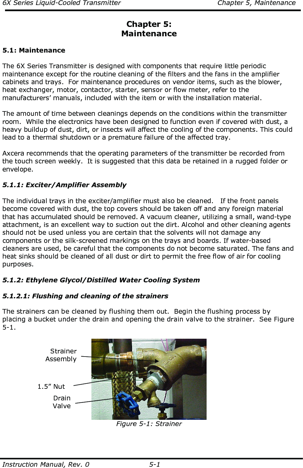
![6X Series Liquid-Cooled Transmitter Chapter 5, Maintenance Instruction Manual, Rev. 0 5-2 Figure 5-2: Input and Output Valves Let the water run for approximately 3 seconds. This should clean the strainer. Repeat for the strainer in the other line. Periodically, the strainers should be removed and cleaned. This is accomplished by first isolating the desired pump and strainer by turning off the input and output valves to the pump. See Figure 5-2. Place a bucket under the drain and open the drain valve. Remove the 1.5” nut from the bottom of the strainer assembly and remove the strainer, noting the orientation of the strainer. Clean the strainer, may need to use a metal brush, and return it to the strainer assembly in the same position as removed. Tighten the 1.5” nut. Repeat for the strainer in the other line. Turn on the input and output valves to the pump. Also, check and clean the single strainer located in the input line to the reservoir tank in the same manner as described for the output strainers. If you are doing the initial installation flushing, connect the water lines to the 6X and the Test Load. 5.1.2.2: Checking the glycol concentration level and PH value It is recommended to use Dow Chemicals’ Dowtherm SR-1 at a 50/50 mix with distilled water for cooling the 6X transmitter. The concentration and condition of the mixture should be checked monthly. This can be done with a hydrometer, if the temperature of the mixture is known. However, a refractometer will indicate the concentration regardless of the temperature of the mixture. To test the coolant mixture for pH and concentration, Axcera recommends the use of a pH-meter supplied by Misco and a refractometer supplied by Misco (7084 VP+ [oF] or 7064 VP+ [oC]). The pH value of the mixture is important. The glycol mixture must be monitored at monthly intervals for the pH value. The desired range of the value is between 8 and 10. If this value falls below 8 and is ignored, the mixture will rapidly become acidic and could damage the 6X amplifier trays. When the pH value of the mixture falls below 8, the entire mixture must be replaced or a small, 50% diluted quantity of sodium hydroxide (very caustic) or potassium hydroxide (less caustic) should be added to the system. This will bring the pH back into the required range. The use of sodium hydroxide or potassium hydroxide can only be repeated three times, after which the whole mixture should be replaced. If, when the coolant is inspected, the color of the glycol mixture has changed to gray or black, or there is an oily layer, a burnt odor, or any sludge in the mixture, this will indicate a need for the replacement of the entire mixture. Output Valves Input Valves](https://usermanual.wiki/UBS-Axcera/6U4AD.Instruction-manual/User-Guide-1231976-Page-45.png)