UBS Axcera HU5000AD 5000-Watt UHF Digital Transmitter User Manual Title Page Vol 2
UBS-Axcera 5000-Watt UHF Digital Transmitter Title Page Vol 2
Contents
- 1. Compiled Users Manual Volume 1
- 2. Compiled Users Manual Volume 2
- 3. Compled Axciter Manual Part 1
- 4. Axciter Manual Part 2
Compiled Users Manual Volume 2

Instruction Manual
InnovatorTM HX Series
Digital UHF
Solid State
Transmitter
Volume 2
UHF Amplifier Cabinet
AXCERA , LLC
103 FREEDOM DRIVE • P.O. BOX 525 • LAWRENCE, PA 15055-0525 USA
(724) 873-8100 • FAX (724) 873-8105
www.axcera.com • service@axcera.com

Innovator® HX Series, Digital, Table of Contents
UHF Transmitter
Volume 2, Rev. 0 i July 7, 2008
TABLE OF CONTENTS
CHAPTER 1 INTRODUCTION
SECTION PAGE
1.1 Manual Overview...................................................................................1-1
1.2 Safety..................................................................................................1-1
1.3 Assembly Designators............................................................................1-2
1.4 Material Return Procedure ......................................................................1-2
1.5 Limited One-Year Warranty for Axcera Products........................................1-3
CHAPTER 2 UHF AMPLIFIER CABINET
2.1 Cabinet Overview ..................................................................................2-1
2.2 Description of the UHF Amplifier Cabinet..................................................2-2
2.2.1 5 kW Amplifier Cabinet with 8 Amplifier Assemblies ........................2-2
2.2.2 3.7 kW Amplifier Cabinet with 6 Amplifier Assemblies......................2-2
2.2.3 2.5 kW Amplifier Cabinet with 4 Amplifier Assemblies......................2-3
2.2.4 1.8 kW Amplifier Cabinet with 3 Amplifier Assemblies......................2-3
2.3 Description of the UHF Amplifier Tray ......................................................2-5
2.3.1 Description of the 8 Way Combiner Assembly (5 kW).......................2-6
2.3.1.1 Description of the 6 Way Combiner Assembly (3.7 kW)...........2-7
2.3.1.2 Description of the 4 Way Combiner Assembly (2.5 kW)...........2-7
2.3.1.3 Description of the 3 Way Combiner Assembly (1.8 kW)...........2-8
2.3.2 Removal of an Amplifier Assembly .................................................2-8
2.3.3 Amplifier Cabinet Power Supply Assemblies.....................................2-9
2.3.4 Control and Monitoring .................................................................2-9
2.3.5 Cabinet Cooling............................................................................2-9
2.4 Cabinet Controller Assembly.................................................................2-11
2.4.1 Controller Connections to the Transmitter’s System Controller ........2-12
2.4.2 Controller Connections to the Amplifier Cabinet Components ..........2-12
2.4.2.1 Power Amplifiers ...............................................................2-12
2.4.2.2 High Power Supply Controllers............................................2-13
2.4.2.3 Low Power Supply and AC Line Monitoring...........................2-13
2.4.2.4 Air Temperature and Amplifier Temperature Monitoring.........2-14
2.4.2.5 RF Power Monitoring..........................................................2-14
2.4.2.6 Reject Load Monitoring ......................................................2-15
2.4.3 Cabinet Controller Settings..........................................................2-15
2.4.4 Cooling Blower Control................................................................2-15
2.4.5 Cabinet Controller Problem Resolution Guide.................................2-16
2.5 Functional Description of Amplifier Cabinet.............................................2-18
2.5.1 Signal Path................................................................................2-18
2.5.2 Test Signal Evaluation.................................................................2-18
2.5.3 Regulation of Transmitter Output Power .......................................2-18
2.5.4 Fault Protection Circuitry.............................................................2-18
2.5.5 Capture of Operating Values in the Amplifiers................................2-19
2.5.6 Amplifier Cabinet Connections .....................................................2-19
2.6 Service...............................................................................................2-20
2.6.1 Safety Information .....................................................................2-20
2.6.1.1 Labeling of Dangerous Substances......................................2-20
2.6.2 Test point Evaluation ..................................................................2-20
2.6.3 Display of Operating Values.........................................................2-20
2.7 Exchange of an Amplifier Module...........................................................2-21

Innovator® HX Series, Digital, Table of Contents
UHF Transmitter
Volume 2, Rev. 0 ii July 7, 2008
TABLE OF CONTENTS (continued)
CHAPTER 3 UHF AMPLIFIER ASSEMBLY & CABINET ASSEMBLIES
CIRCUIT DESCRIPTIONS
SECTION PAGE
3.1 Amplifier Overview ................................................................................3-1
3.2 Design of the UHF Amplifier....................................................................3-2
3.2.1 Capture of Test Values in the UHF Amplifier ....................................3-5
3.2.2 Functional Description of the Boards in the Amplifier Assembly .........3-6
3.2.2.1 40W UHF Module Assembly..................................................3-6
3.2.2.2 UHF Module Assembly .........................................................3-6
3.2.2.3 Coupler Board.....................................................................3-6
3.2.2.4 4 Way Splitter Board ...........................................................3-7
3.2.2.5 UHF Dual Stage Pallets ........................................................3-7
3.2.2.6 4 Way Combiner Board........................................................3-7
3.2.2.7 FET Switch/Metering Board ..................................................3-8
3.2.2.7.1 Operating voltages for the Amplifier Boards.................3-8
3.2.2.8 Amplifier Control Board........................................................3-8
3.2.2.8.1 Schematic Page 1 .....................................................3-9
3.2.2.8.2 Schematic Page 2 .....................................................3-9
3.2.2.8.3 Schematic Page 3 ...................................................3-10
3.2.2.8.4 Schematic Page 4 ...................................................3-10
3.2.2.8.5 Schematic Page 5 ...................................................3-10
3.3 Troubleshooting and Repair of the Amplifier ...........................................3-11
3.3.1 Safety Information .....................................................................3-11
3.3.2 Troubleshooting .........................................................................3-11
3.3.2.1 Front Panel LEDs...............................................................3-11
3.3.2.2 Polling Fault Indications .....................................................3-11
3.4 Exchanging Amplifiers..........................................................................3-11
3.4.1 Exchange of a Module.................................................................3-12
3.4.2 Mounting a New Module..............................................................3-12
3.4.3 Final Steps ................................................................................3-12
3.4.4 External Connections to Amplifier Assembly ..................................3-12
3.5 Power Supply Assembly .......................................................................3-13
3.5.1 Overview of the +32V Power Supply Unit......................................3-13
3.5.2 Description of SCR Controllers .....................................................3-14
3.5.3 Description of the Step Down Transformers ..................................3-14
3.5.4 Description of the Linear Power Supply Assemblies ........................3-14
3.6 Full Amplifier Cabinet Controller Board...................................................3-16
3.6.1 Page 1 of Schematic 1307524 .....................................................3-16
3.6.2 Page 2 of Schematic 1307524 .....................................................3-16
3.6.3 Page 3 of Schematic 1307524 .....................................................3-17
3.6.4 Page 4 of Schematic 1307524 .....................................................3-17
3.6.5 Page 5 of Schematic 1307524 .....................................................3-17
3.7 Half Amplifier Cabinet Controller Board..................................................3-19
3.7.1 Page 1 of Schematic 1307841 .....................................................3-19
3.7.2 Page 2 of Schematic 1307841 .....................................................3-19
3.7.3 Page 3 of Schematic 1307841 .....................................................3-20
3.7.4 Page 4 of Schematic 1307841 .....................................................3-20
3.7.5 Page 5 of Schematic 1307841 .....................................................3-20
3.8 Temperature Sensor Board...................................................................3-21
3.9 Reflected Metering Board .....................................................................3-21

Innovator® HX Series, Digital, Table of Contents
UHF Transmitter
Volume 2, Rev. 0 iii July 7, 2008
TABLE OF CONTENTS (continued)
SECTION PAGE
3.10 Serial Loop-Thru Board......................................................................3-21
3.11 Load Regulator Assembly ...................................................................3-21
3.11.1 Load Regulator Board ...............................................................3-22
APPENDICES
APPENDIX A RF AMPLIFIER CABINET ASSEMBLY, HX SERIES
DRAWINGS AND PARTS LISTS
APPENDIX B UHF AMPLIFIER ASSEMBLY, HX SERIES
DRAWINGS AND PARTS LISTS
APPENDIX C +32 VDC POWER SUPPLY ASSEMBLIES, TOP AND BOTTOM
DRAWINGS AND PARTS LISTS

Innovator® HX Series, Digital, Table of Contents
UHF Transmitter
Volume 2, Rev. 0 iv July 7, 2008
LIST OF FIGURES
FIGURE PAGE
1-1 Typical Brady Marker Identification Drawing......................................1-2
2-1 Typical UHF Amplifier Cabinet (Front View) .......................................2-1
2-2 Block Diagram Typical UHF Amplifier Cabinet 8 Way (5 kW)................2-1
2-3 Block Diagram Typical UHF Amplifier Cabinet 4 Way (2.5 kW).............2-4
2-4 Components in the Amplifier Cabinet................................................2-4
2-5 Block Diagram Typical UHF Amplifier Tray Assembly ..........................2-5
2-6 Block Diagram Typical 8 Way UHF Combiner Assembly.......................2-6
2-7 Block Diagram Typical 4 Way UHF Combiner Assembly.......................2-8
2-8 Air Flow in the Amplifier Cabinet ....................................................2-10
2-9A Full Cabinet Controller Assembly....................................................2-10
2-9B Half Cabinet Controller Assembly ...................................................2-10
2-10 Amplifier Cabinet Connections .......................................................2-19
2-11 Labeling of Toxic Substances in Drawings .......................................2-20
2-12 Location and Assignment of the Circuit Breakers and LEDs ...............2-21
2-13 Amplifier Tray Lock Location..........................................................2-22
3-1 UHF Amplifier Assembly..................................................................3-1
3-2 Remaining Power after Failure of Amplifier Modules............................3-2
3-3 Location of the Assemblies in the UHF Amplifier.................................3-3
3-4 Block Diagram of the UHF Amplifier..................................................3-4
3-5 Interconnect Typical UHF Amplifier Assembly ....................................3-5
3-6 AC Wiring Harness UHF Amplifier Cabinet........................................3-13
3-7 Interconnect Linear Power Supply #1, Top......................................3-14
3-8 Interconnect Linear Power Supply #2, Bottom.................................3-15
3-9 Control Interconnect Cabinet Full Controller System.........................3-15
3-10 Control Interconnect Cabinet Half Controller System........................3-18

Innovator® HX Series, Digital, Table of Contents
UHF Transmitter
Volume 2, Rev. 0 v July 7, 2008
LIST OF TABLES
TABLE PAGE
2-1 Serial Cable Pin Out......................................................................2-12
2-2 Cabinet Controller DIP Switch Settings ...........................................2-14
2-3 Cabinet Controller Assembly Problem Resolution Guide ....................2-16
2-4 Amplifier Cabinet Connections .......................................................2-20
3-1 Assemblies in the UHF Amplifier.......................................................3-2
3-2 Module OK LED Red and Blinking Interpretation.................................3-5
3-3 Module OK LED Red and Blinking Interpretation.................................3-9
3-4 Module OK LED Red and Blinking Interpretation...............................3-11
3-5 RF Connectors on the Front Panel ..................................................3-12
3-6 Operating Voltage Connection (Rear Panel).....................................3-12
3-7 Configuration of SW2 on Full Amplifier Cabinet Control Board............3-17
3-8 Configuration of SW2 on Half Amplifier Cabinet Control Board...........3-21

Innovator HX Series Digital Chapter 1, Introduction
UHF Transmitter
Volume 2, Rev. 0 1-1
Chapter 1
Introduction
The InnovatorTM HX Series UHF digital
solid-state transmitter is comprised of
two cabinet types: An exciter/control
cabinet and a UHF amplifier cabinet.
Every InnovatorTM HX includes one or
more of each cabinet type, dependent
upon the power configuration ordered.
This volume, Volume 2, of the manual
describes the UHF amplifier cabinet
portion of the transmitter. The system
and the exciter/control assemblies are
covered in Volume 1.
1.1: Manual Overview
Volume 2, of the Innovator HX Series
Digital UHF Transmitter Instruction
Manual, is divided into three chapters
and supporting appendices. Chapter 1,
Introduction, contains information on
safety, return procedures, and
warranties. Chapter 2, Amplifier
Cabinet, describes the UHF amplifier
cabinet. Chapter 3, UHF Amplifier Tray
Assembly and Cabinet Assemblies Circuit
Descriptions, contains a detailed
discussion of the UHF amplifier module
and power supply assemblies that are
contained in the cabinet. Appendix A
contains the RF amplifier cabinet
assembly drawings and parts lists.
Appendix B contains the UHF amplifier
assembly drawings and parts lists.
Appendix C contains the top and bottom
+32VDC power supply assemblies
drawings and parts lists.
1.2: Safety
The HX Series UHF transmitters
manufactured by Axcera are designed to
be easy to use and repair while providing
protection from electrical and mechanical
hazards. Listed throughout the manual
are notes, cautions, and warnings
concerning possible safety hazards that
may be encountered while operating or
servicing the transmitter. It is important
that users review these warnings and
become familiar with the operation and
servicing procedures before working on
the transmitter.
Read All Instructions – It is important
that any user of this equipment read
and understand all of the operating and
safety instructions, especially the safety
information in this chapter, before
operating the Transmitter.
Retain Manuals – The manuals for the
transmitter should be retained at the
transmitter site for future reference. We
provide two sets of manuals for this
purpose; one set can be left at the office
while one set can be kept at the site.
Heed all Notes, Warnings, and
Cautions – All of the notes, warnings,
and cautions listed in this safety section
and throughout the manual must be
followed.
Follow Instructions – All of the
operating and use instructions for the
transmitter should be followed.
Cleaning – Unplug or otherwise
disconnect all power from the equipment
before cleaning. Do not use liquid or
aerosol cleaners. Use a damp cloth for
cleaning.
Servicing – Do not attempt to service
this product until becoming familiar with
the equipment. If in doubt, refer all
servicing questions to qualified Axcera
service personnel.
Replacement Parts – When
replacement parts are needed, be sure
that the parts have the same functional
and performance characteristics as the
original part. Unauthorized substitutions
may result in fire, electric shock, or other
hazards. Please contact the Axcera
Technical Service Department with any
questions regarding service or
replacement parts.

Innovator HX Series Digital Chapter 1, Introduction
UHF Transmitter
Volume 2, Rev. 0 1-2
1.3: Assembly Designators
Axcera has assigned assembly numbers,
Ax designations such as A1, where
x=1,2,3…etc, to all assemblies, modules,
and boards in the system. These
designations are referenced in the text of
this manual and shown on the block
diagrams and interconnect drawings
provided in the appendices. The Block
Diagrams, Interconnects, Schematics,
Assembly Drawings and Parts Lists are
arranged in increasing numerical order in
the appendices. Section titles in the text
for assembly or module descriptions or
alignment procedures contain the
associated part number(s) and the
relevant appendix that contains the
drawings for that item.
The cables that connect between the
boards within a tray or assembly and
that connect between the trays, racks
and cabinets are labeled using Brady
markers.
Figure 1-1 is an example of a Brady
marked cable. There may be as few as
two or as many as four Markers on any
one cable. These Brady markers are
read starting farthest from the
connector. If there are four Brady
Markers, this marker is the transmitter
number such as transmitter 1 or
Transmitter 2. The next or the farthest
Brady Marker is the rack or cabinet
number on an interconnect cable or the
board number within a tray. The next
number on an interconnect cable is the
Tray location or number. The Brady
marker closest to the connector is the
Jack or Connector number on an
interconnect cable or the jack or
connector number on the board within a
tray.
Figure 1-1: Brady Marker Identification
Drawing
1.4: Material Return Procedure
To insure the efficient handling of
equipment or components that have been
returned for repair, Axcera requests that
each returned item be accompanied by a
Return Material Authorization Number
(RMA#).
An RMA# can be obtained from any
Axcera Service Engineer by contacting
the Axcera Technical Service Department
at 1-724-873-8100 or by fax at 1-724-
873-8105. This procedure applies to all
items sent to the Technical Service
Department regardless of whether the
item was originally manufactured by
Axcera.
When equipment is sent to the field on
loan, an RMA# is included with the unit.
The RMA# is intended to be used when
the unit is returned to Axcera. In
addition, all shipping material should be
retained for the return of the unit to
Axcera.
Replacement assemblies are also sent
with an RMA# to allow for the proper
routing of the exchanged hardware.
Failure to close out this type of RMA# will
normally result in the customer being
invoiced for the value of the loaner item
or the exchange assembly.
When shipping an item to Axcera, please
include the RMA# on the packing list and
on the Axcera-provided shipping
container. The packing slip should also
include contact information and a brief
description of why the unit is being
returned.
Please forward all RMA items to:
Axcera
Customer Service Department
103 Freedom Drive
P.O. Box 525
Lawrence, PA 15055-0525 USA

Innovator HX Series Digital Chapter 1, Introduction
UHF Transmitter
Volume 2, Rev. 0 1-3
For more information concerning this
procedure, call the Axcera Technical
Service Department.
Service can also be contacted through e-
mail at service@axcera.com and on the
Web at www.axcera.com.
1.5: Limited One-Year Warranty for
Axcera Products
Axcera warrants each new product that
it has manufactured and sold against
defects in material and workmanship
under normal use and service for a
period of one (1) year from the date of
shipment from Axcera's plant, when
operated in accordance with Axcera's
operating instructions. This warranty
shall not apply to tubes, fuses,
batteries, or bulbs.
Warranties are valid only when and if
(a) Axcera receives prompt written
notice of breach within the period of
warranty, (b) the defective product is
properly packed and returned by the
buyer (transportation and insurance
prepaid), and (c) Axcera determines, in
its sole judgment, that the product is
defective and not subject to any misuse,
neglect, improper installation,
negligence, accident, or (unless
authorized in writing by Axcera) repair
or alteration.
Axcera's exclusive liability for any
personal and/or property damage
(including direct, consequential, or
incidental) caused by the breach of any
or all warranties, shall be limited to the
following: (a) repairing or replacing (in
Axcera's sole discretion) any defective
parts free of charge (F.O.B. Axcera’s
plant) and/or (b) crediting (in Axcera's
sole discretion) all or a portion of the
purchase price to the buyer.
Equipment furnished by Axcera, but not
bearing its trade name, shall bear no
warranties other than the special hours-
of-use or other warranties extended by
or enforceable against the manufacturer
at the time of delivery to the buyer.
NO WARRANTIES, WHETHER
STATUTORY, EXPRESSED, OR
IMPLIED, AND NO WARRANTIES OF
MERCHANTABILITY, FITNESS FOR
ANY PARTICULAR PURPOSE, OR
FREEDOM FROM INFRINGEMENT,
OR THE LIKE, OTHER THAN AS
SPECIFIED IN PATENT LIABILITY
ARTICLES, AND IN THIS ARTICLE,
SHALL APPLY TO THE EQUIPMENT
FURNISHED HEREUNDER.

Innovator HX Series Digital Chapter 1, Introduction
UHF Transmitter
Volume 2, Rev. 0 1-4
F WARNING!!!
× HIGH VOLTAGE Ø
DO NOT ATTEMPT TO REPAIR OR TROUBLESHOOT THIS EQUIPMENT UNLESS
YOU ARE FAMILIAR WITH ITS OPERATION AND EXPERIENCED IN
SERVICING HIGH VOLTAGE EQUIPMENT. LETHAL VOLTAGES ARE PRESENT
WHEN POWER IS APPLIED TO THIS SYSTEM. IF POSSIBLE, TURN OFF
POWER BEFORE MAKING ADJUSTMENTS TO THE SYSTEM.
« RADIO FREQUENCY RADIATION HAZARD «
MICROWAVE, RF AMPLIFIERS AND TUBES GENERATE HAZARDOUS RF
RADIATION THAT CAN CAUSE SEVERE INJURY INCLUDING CATARACTS,
WHICH CAN RESULT IN BLINDNESS. SOME CARDIAC PACEMAKERS MAY BE
AFFECTED BY THE RF ENERGY EMITTED BY RF AND MICROWAVE
AMPLIFIERS. NEVER OPERATE THE TRANSMITTER SYSTEM WITHOUT A
PROPERLY MATCHED RF ENERGY ABSORBING LOAD ATTACHED. KEEP
PERSONNEL AWAY FROM OPEN WAVEGUIDES AND ANTENNAS. NEVER
LOOK INTO AN OPEN WAVEGUIDE OR ANTENNA. MONITOR ALL PARTS OF
THE RF SYSTEM FOR RADIATION LEAKAGE AT REGULAR INTERVALS.

Innovator HX Series Digital Chapter 1, Introduction
UHF Transmitter
Volume 2, Rev. 0 1-5
EMERGENCY FIRST AID INSTRUCTIONS
Personnel engaged in the installation, operation, or maintenance of this equipment are urged to become
familiar with the following rules both in theory and practice. It is the duty of all operating personnel to be
prepared to give adequate Emergency First Aid and thereby prevent avoidable loss of life.
RESCUE BREATHING
1. Find out if the person is
breathing.
You must find out if the person
has stopped breathing. If you
think he is not breathing, place
him flat on his back. Put your ear
close to his mouth and look at his
chest. If he is breathing you can
feel the air on your cheek. You
can see his chest move up and
down. If you do not feel the air
or see the chest move, he is not
breathing.
2. If he is not breathing, open
the airway by tilting his head
backwards.
Lift up his neck with one hand
and push down on his forehead
with the other. This opens the
airway. Sometimes doing this will
let the person breathe again by
himself.
3. If he is still not breathing,
begin rescue breathing.
-Keep his head tilted backward.
Pinch nose shut.
-Put your mouth tightly over his
mouth.
-Blow into his mouth once every
five seconds
-DO NOT STOP rescue breathing
until help arrives.
LOOSEN CLOTHING - KEEP
WARM
Do this when the victim is
breathing by himself or help is
available. Keep him as quiet as
possible and from becoming
chilled. Otherwise treat him for
shock.
BURNS
SKIN REDDENED: Apply ice cold water to burned
area to prevent burn from going deeper into skin
tissue. Cover area with a clean sheet or cloth to
keep away air. Consult a physician.
SKIN BLISTERED OR FLESH CHARRED: Apply
ice cold water to burned area to prevent burn from
going deeper into skin tissue.
Cover area with clean sheet or cloth to keep away
air. Treat victim for shock and take to hospital.
EXTENSIVE BURN - SKIN BROKEN: Cover area
with clean sheet or cloth to keep away air. Treat
victim for shock and take to hospital.
Innovator HX Series Digital Chapter 2, Amplifier Cabinet
UHF Transmitter
Volume 2, Rev. 0 2-1
Chapter 2
Amplifier Cabinet
2.1: Cabinet Overview
The fully populated amplifier cabinets
used in Innovator HX Transmitters
contain eight UHF amplifiers connected
in parallel (Figure 2-1). The number of
amplifiers varies according to the
needed output power for the
transmitter. The amplifiers operate,
without the need for tuning or
alignment, on the UHF channel
designated.
All equipment in the cabinet is fully
solid-state and designed for high-
operational reliability and a service-
friendly layout. The cabinet is cooled by
external air cooling equipment. The
cooling air is ducted into and out of the
top of the cabinet.
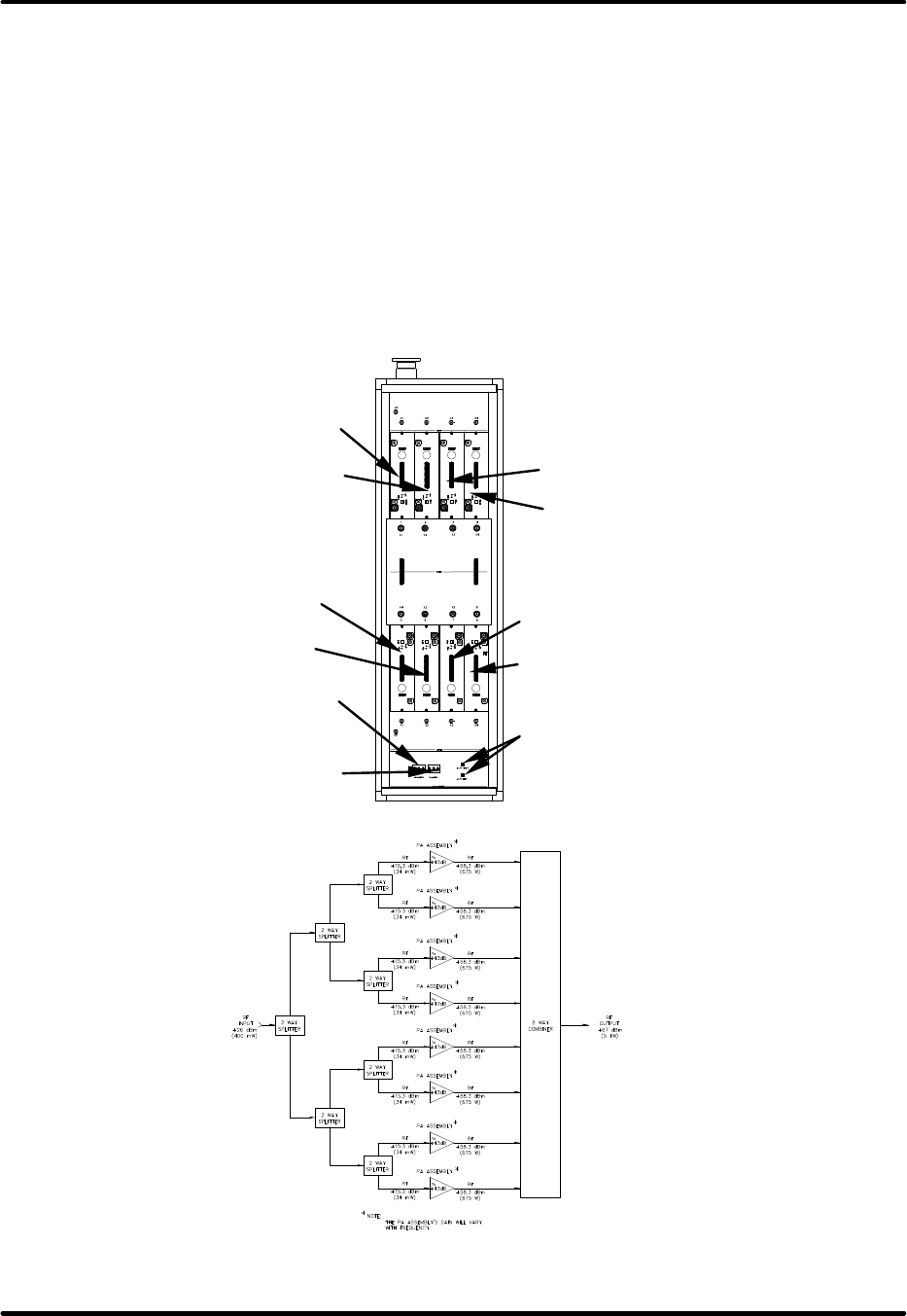
Figure 2-1: Typical 8 Way UHF Amplifier Cabinet (Front View)
Figure 2-2: Block Diagram of the typical UHF Amplifier Cabinet 8 Way (5kW)
POWER SUPPLY #1
CIRCUIT BREAKER
POWER SUPPLY #2
CIRCUIT BREAKER
(A19) UHF AMPLIFIER #3
(Not present in 2.5kW)
(A20) UHF AMPLIFIER #4
(Not present in 2.5kW)
(A17) UHF AMPLIFIER #1
(Not present i
n 2.5kW)
(A18) UHF AMPLIFIER #2
(Not present in 2.5kW)
(A23) UHF AMPLIFIER #7
(A24) UHF AMPLIFIER #8
(A21) UHF AMPLIFIER #5
(A22) UHF AMPLIFIER #6
±12VDC POWER SUPPLY
RESET BREAKERS

Innovator HX Series Digital Chapter 2, Amplifier Cabinet
UHF Transmitter
Volume 2, Rev. 0 2-2
2.2: Description of the UHF Amplifier
Cabinet
The features of the amplifier cabinet
include: 1) Amplifiers that are 100%
transistors. 2) High redundancy due to
the parallel connection of power
transistors. 3) A mean junction
temperatures less than 120° C. 4)
Multiple fault protection circuitry in each
amplifier. 5) A power supply for
Amplifiers 1 thru 3 (3.7kW) and 4
(5kW). 6) A separate power supply for
Amplifiers 6 thru 8 (1.8kW) and 5
(2.5kW & 5kW). 7) Amplifiers that
operate over the selected band of UHF
frequencies without the need for
alignment. 8) The important operating
parameters are displayed in the
transmitter touch screen control unit. 9)
There are multiple test points in the
signal path. 10) It has air cooling, with
the input and output air connections on
the top of the amplifier cabinet.
The amplifier assemblies in each
amplifier cabinet (see Figure 2-3) are
slide-in units, inserted from the front.
In a 5kW cabinet, two 4 way splitters
are installed, one in the top and one in
the bottom half of the cabinet. In a 2.5
kW cabinet, just the bottom 4 way
splitter is present. These splitters
distribute the RF input to each of the
amplifiers. In a 3.7kW cabinet, 3 way
splitters are installed in the top and
bottom half of the cabinet. In a 1.8 kW
cabinet, just the bottom 3 way splitter is
present. These distribute the RF input
to each of the amplifiers. A 3, 4, 6 or 8
way combiner is installed in the middle
of the cabinet. The lower part of the
cabinet accommodates a power
distribution panel that contains two 480
VAC 30 Amp 3 Phase or 208 VAC 50
Amp 3 Phase circuit breakers for 3.7 & 5
kW or one circuit breaker for 1.8 & 2.5
kW. The left breaker, if present,
distributes the main AC voltage to the
top power supply and the right circuit
breaker controls the bottom power
supply. The top power supply provides
the +32 VDC to the top three or four
amplifier assemblies. The bottom power
supply provides the +32 VDC to the
bottom three or four amplifier
assemblies
There is also either one or two 1 Amp
reset circuit breakers, mounted on the
power distribution panel that protect the
AC voltage to the switching power
supply, located in the bottom and top
power supply. If one breaker is present,
it connects to the bottom power supply,
for 1.8 & 2.5 kW. If 2 one Amp reset
breakers are present, the second one
amp breaker connects to the top power
supply for 3.7 & 5 kW. The switching
supply provides the ±12 VDC to the top
and bottom amplifier assemblies.
2.2.1: 5 kW Amplifier Cabinet with 8
Amplifier Assemblies
Refer to Figure 2-2. The DTV RF signal
from the exciter/control cabinet is
connected through RG-55 cable through
an opening in the roof in the UHF
amplifier cabinet. The RF (+26 dBm,
400 mW) from the output of the exciter
control cabinet connects to the SMA “S”
input on (A14) a 2 way splitter with each
of the two outputs connecting to a 4
way splitter panel (A15 top & A16
bottom). The four outputs of the (A15-
A1) Top 4 way splitter are at the “N”
connectors X1-X4.
The outputs (+15.3 dBm, 34 mW)
connect to the (A17) UHF amplifier #1,
(A18) UHF amplifier #2, (A19) UHF
amplifier #3 and (A20) UHF amplifier
#4. Each amplifier tray has a gain of
approximately +40.5dB. The four
outputs of the (A16-A1) Bottom 4 way
splitter, at “N” connectors X1-X4,
connect to the (A21) UHF amplifier #5,
(A22) UHF amplifier #6, (A23) UHF
amplifier #7, and (A24) UHF amplifier
#8. The eight outputs of the amplifier
modules at 7/16” connectors (+58.3
dBm, 675W) are cabled to the (A24) 8
way combiner. The output of the
combiner connects to the (A26) RF
coupler. The output of the cabinet is

Innovator HX Series Digital Chapter 2, Amplifier Cabinet
UHF Transmitter
Volume 2, Rev. 0 2-3
approximately (+67.2 dBm, 5.2kW) at
the 3-1/8” output connector of the (A26)
RF Coupler Assembly.
2.2.2: 3.7 kW Amplifier Cabinet with
6 Amplifier Assemblies
The DTV RF signal from the
exciter/control cabinet is connected
through RG-55 cable through an opening
in the roof in the UHF amplifier cabinet.
The RF (+27 dBm, 500 mW) from the
output of the exciter control cabinet
connects to the SMA “S” input on (A14)
a 2 way splitter with each of the two
outputs connecting to a 3 way splitter
panel (A15 top & A16 bottom). The
three outputs of the (A15) Top 3 way
splitter are at the “N” connectors X1-X3.
The outputs (+18 dBm, 63 mW) connect
to the (A17) UHF amplifier #1, (A18)
UHF amplifier #2 and (A19) UHF
amplifier #3. The three outputs of the
(A16) Bottom 3 way splitter, at “N”
connectors X2-X4, connect to the (A22)
UHF amplifier #6, (A23) UHF amplifier
#7, and (A24) UHF amplifier #8. Each
amplifier tray has a gain of
approximately +40.5dB. The six
outputs of the amplifier modules at
7/16” connectors (+58.5 dBm, 700W)
are cabled to the (A24) 6 way combiner.
The output of the combiner connects to
the (A26) RF coupler. The output of the
cabinet is approximately (+65.7 dBm,
3.7 kW) at the 3-1/8” output connector
of the (A26) RF Coupler Assembly.
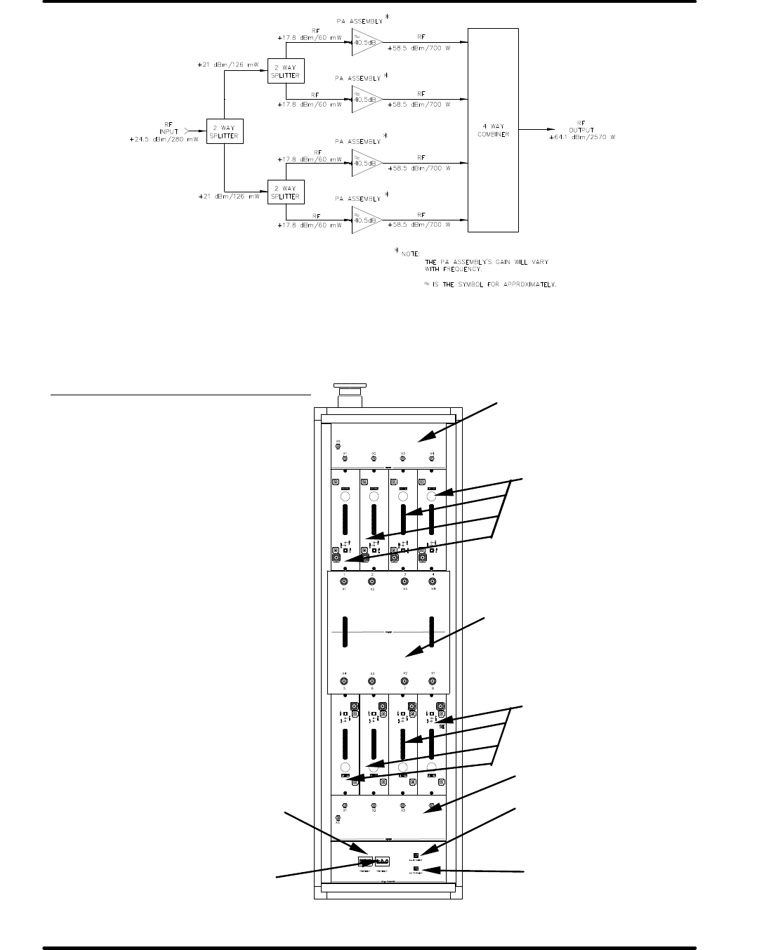
2.2.3: 2.5 kW Amplifier Cabinet with
4 Amplifier Assemblies
Refer to Figure 2-3. The DTV RF signal
from the exciter/control cabinet is
connected through RG-55 cable through
an opening in the roof in the UHF
amplifier cabinet. The RF (+26 dBm,
400 mW) from the output of the exciter
control cabinet connects to the 4 way
splitter panel (A16) mounted at the
bottom of the cabinet. The four outputs
of the (A16-A1) 4 way splitter, at “N”
connectors X1-X4, connect to the (A21)
UHF amplifier #5, (A22) UHF amplifier
#6, (A23) UHF amplifier #7, and (A24)
UHF amplifier #8. Each amplifier tray
has a gain of approximately +40.5dB.
The four outputs of the amplifier
modules at 7/16” connectors (+58.5
dBm, 700W) are cabled to the (A25) 4
way combiner assembly. The combiner
produces a single output that connects
to the (A26) RF Coupler Assembly. The
RF output for the cabinet, approximately
+64.1 dBm, 2570 Watts, is at the 3-1/8”
output connector of the RF Coupler
Assembly.
2.2.4: 1.8 kW Amplifier Cabinet with
3 Amplifier Assemblies
The DTV RF signal from the
exciter/control cabinet is connected
through RG-55 cable through an opening
in the roof in the UHF amplifier cabinet.
The RF (+27 dBm, 500 mW) from the
output of the exciter control cabinet
connects to the 3 way splitter panel
(A16) mounted at the bottom of the
cabinet. The three outputs of the (A16)
3 way splitter, at “N” connectors X2-X4,
connect to the (A22) UHF amplifier #6,
(A23) UHF amplifier #7, and (A24) UHF
amplifier #8. Each amplifier tray has a
gain of approximately +40.5dB. The
three outputs of the amplifier modules
at 7/16” connectors (+58.5 dBm, 700W)
are cabled to the (A25) 3 way combiner
assembly. The combiner produces a
single output that connects to the (A26)
RF Coupler Assembly. The RF output for
the cabinet, approximately +62.6 dBm,
1800 Watts, is at the 3-1/8” output
connector of the RF Coupler Assembly.
Innovator HX Series Digital Chapter 2, Amplifier Cabinet
UHF Transmitter
Volume 2, Rev. 0 2-4
Figure 2-3: Block Diagram of the typical UHF Amplifier Cabinet 4 Way (2.5kW)
Figure 2-4: Components in the Amplifier Cabinet
Components in the Amplifier Cabinet
8 UHF Amplifier Trays (5kW)
6 UHF Amplifier Tray (3.7kW)
2 Power Supply Assemblies (3.7 &
5kW)
4 UHF Amplifier Trays (2.5kW)
3 UHF Amplifier Trays (1.8kW)
1 Power Supply Assembly (1.8 &
2.5kW)
One Circuit Breaker Assembly
One 3, 4, 6 or 8 Way Combiner
Assembly
Splitter 1 : 4 (5kW)
Splitter 1 : 3 (3.7kW)
Splitter 1 : 4 (2.5kW & 5kW)
Splitter 1 : 3 (1.8kW & 3.7kW)
Circuit Breaker for Top
12VDC Power Supply (3.7kW &
5kW) Assembly
UHF Amplifier Trays (A17,
A18, A19 & A20) (5kW)
(A20) not used in 3.7kW
UHF Amplifier Trays
(A21, A22, A23 & A24)
(2.5kW & 5kW)
(A21) not used in 1.8 & 2.7kW
Combiner 8 : 1 (5kW)
Combiner 6 : 1 (3.7kW)
Combiner 4 : 1 (2.5kW)
Combiner 3 : 1 (1.8kW)
Circuit Breaker for Top
+32VDC Power Supply (3.7kW & 5kW)
Circuit Breaker for Bottom +32VDC
Power Supply (1.8, 2.5 3.7 & 5kW)
Circuit Breaker for Bottom
12VDC Power Supply (1.8, 2.5 &
5kW) Assembly
Innovator HX Series Digital Chapter 2, Amplifier Cabinet
UHF Transmitter
Volume 2, Rev. 0 2-5
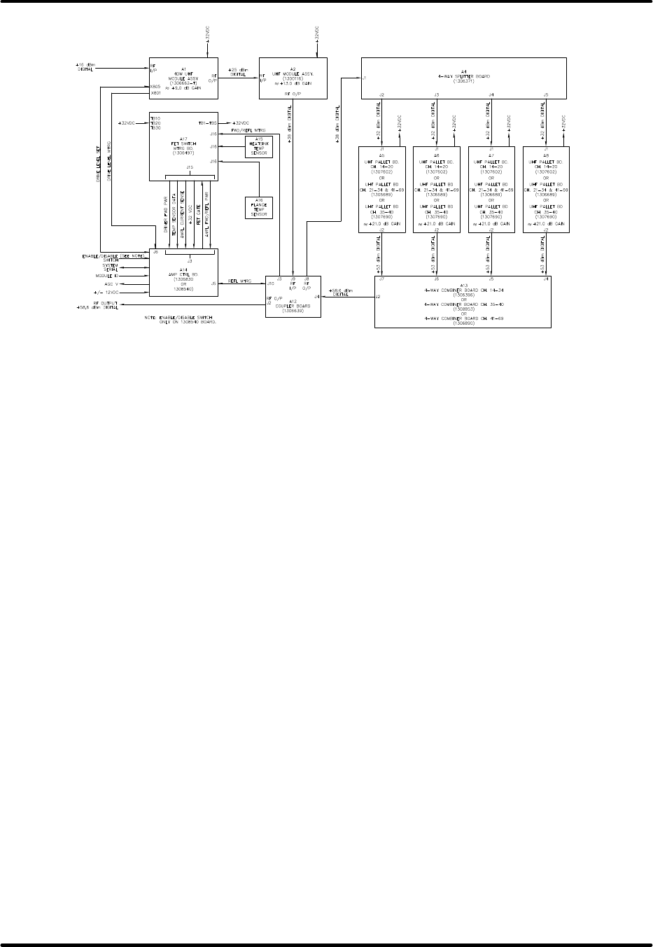
Figure 2-5: Block Diagram Typical UHF Amplifier Tray Assembly
2.3: Description of the UHF Amplifier
Tray
There are eight of these trays in an 8
way Amplifier Cabinet Assembly for
5kW, six in a 6 way Amplifier Cabinet
Assembly for 3.7 kW, four in a 4 way
Amplifier Cabinet Assembly for 2.5 kW,
or three in a 3 way Amplifier Cabinet
Assembly for 1.8 kW. The Amplifier
Tray has an approximate gain of +40.5
dB.
The RF input (+18 dBm) at the “N”
connector J1 on each UHF amplifier
assembly is fed to the RF input
connections on (A1) the 40 Watt UHF
Module Assembly, which is a predriver
assembly with ≈9 dB gain. The output
(+27 dBm) is cabled to the RF input
connections on (A3) a UHF Module Pallet
Assembly (1300116) with ≈13 dB gain.
The UHF Module Pallet Assembly
contains a RF Module Pallet w/o
transistors (1152336). The output (+40
dBm) is fed to J9 on (A12) a Coupler
Board (1306639) that supplies a driver
forward power sample out of J3-5 to the
FET switch/metering board at J1-1. The
sample is not used on the FET
switch/metering board; it is just fed
through to J15-1 that is wired to J3-13
on the (A14) amplifier control board
(1308540 or 1306830) where it is used
in the amplifier protection circuitry.
The output of the coupler board at J8
(+40 dBm) is fed to J1 on (A4) the 4
Way Splitter Board (1306371) where it
is split. Each output of the splitter (+34
dBm) is cabled to the RF Input jack of
one of the four (A5-A8), UHF dual stage
pallet boards, (1307602, CH: 14-20, or
1306689, CH: 21-34 & 41-69), or
1307690, CH: 35-40). Each pallet board
has ≈+21 dB of gain. The outputs of
each amplifier board (+55 dBm) are
combined on (A13) the 4 way combiner
assembly, (1306396, CH: 14-34, or
1308853, CH: 35-40, or 1306890, CH:
41-69).
The RF output jack J2, of the 4 way
combiner assembly (+58.6 dBm), is Bus
wire jumpered to J4 on the (A12)
Coupler Board (1306639) that supplies a
RF sample out at J1. Also, the Coupler
Board provides a final amp forward
metering sample at J3-1 and a final amp
reflected metering sample at J3-2. The
samples are connected to (A17) the FET
switch/metering board (1306497) at J1-
6 and J1-7. The samples are not used
on the FET switch/metering board, they
are just fed through to J15-2 and J15-14
Innovator HX Series Digital Chapter 2, Amplifier Cabinet
UHF Transmitter
Volume 2, Rev. 0 2-6
that are wired to J3-12 and J3-25 on the
amplifier control board where they are
used in the amplifier protection circuitry.
The RF output of the coupler board is at
J2 that is Bus wire connected to J2 the
7/16” connector RF Output Jack of the
amplifier assembly. Typical output level
is +58.5 dBm.
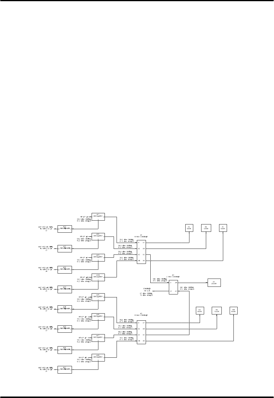
2.3.1: Description of the 8 Way
Combiner Assembly (5 kW Amplifier
Cabinet)
The RF outputs of the eight amplifiers
are combined by means of an 8:1
combiner assembly w/circulators that is
mounted in the middle of the cabinet.
The 8 way combiner is made up of two
identical 4 way combiners and a two
way combiner. Refer to Figure 2-5.
The eight RF inputs, +58.3 dBm in level,
each connect to a separate circulator.
The circulators protect the amplifiers in
the event of high VSWR generated by
the output circuits. A reflected sample
from the circulator is fed through a 30dB
attenuator to one of the two Reflected
Metering Boards (A80 & A81). The A80
Reflected Metering Board has the top
four amplifier assemblies connected to it
and the A81 Reflected Metering Board
has the bottom four amplifier assemblies
connected to it. If one or more of the
reflected samples exceeds 10%, the
affected Reflected Metering Board will
shut down the associated power supply
therefore removing the voltages to the
four amplifier assemblies that it
supplies. The power supply can only be
reset by switching the transmitter to
standby then operate after repair of the
cause for the high VSWR. Each 4 Way
combiner has three dummy loads, two
600W and a 1200W, which dissipate any
power due to an imbalance or mismatch
during the combining of the amplifiers.
The outputs of the 4 way combiners,
each +64.1 dBm, connect to the (A3)
Two Way Combiner. The 2 Way
combiner has a 2500W load connected
to it. The output of the 2 Way
Combiner, which is the output of the 8
Way Combiner Assembly is at the
3 1/8” RF output jack, typically
˜+67 dBm.
Figure 2-6: Block Diagram Typical 8 Way UHF Combiner Assembly w/Circulators

Innovator HX Series Digital Chapter 2, Amplifier Cabinet
UHF Transmitter
Volume 2, Rev. 0 2-7
2.3.1.1: Description of the 6 Way
Combiner Assembly (3.7 kW
Amplifier Cabinet)
The RF outputs of the six amplifiers are
combined by means of an 6:1 combiner
assembly w/circulators that is mounted
in the middle of the cabinet. The 6 way
combiner is made up of two identical 3
way combiners and a two way combiner.
The six RF inputs, +58.5 dBm in level,
each connect to a separate circulator.
The circulators protect the amplifiers in
the event of high VSWR generated by
the output circuits. A reflected sample
from the circulator is fed through a 30dB
attenuator to one of the two Reflected
Metering Boards (A80 & A81). The A80
Reflected Metering Board has the top
three amplifier assemblies connected to
it and the A81 Reflected Metering Board
has the bottom three amplifier
assemblies connected to it. If one or
more of the reflected samples exceeds
10%, the affected Reflected Metering
Board will shut down the associated
power supply therefore removing the
voltages to the four amplifier assemblies
that it supplies. The power supply can
only be reset by switching the
transmitter to standby then operate
after repair of the cause for the high
VSWR. Each 3 Way combiner has two
600W dummy loads, which dissipate any
power due to an imbalance or mismatch
during the combining of the amplifiers.
The outputs of the 3 way combiners,
each +64.1 dBm, connect to the (A5)
Two Way Combiner. The 2 Way
combiner has a 2500W load connected
to it. The output of the 2 Way
Combiner, which is the output of the 6
Way Combiner Assembly is at the
3 1/8” RF output jack, typically
˜+65.7 dBm.
2.3.1.2: Description of the 4 Way
Combiner Assembly (2.5 kW
Amplifier Cabinet)
The RF outputs of the four amplifiers are
combined by means of a 4:1 combiner
assembly that is mounted in the middle
of the cabinet. Refer to Figure 2-7.
The four RF inputs, +58.5 dBm Digital in
level, each connect to a separate
circulator. The circulators protect the
amplifiers in the event of high VSWR
generated by the output circuits. A
reflected sample from the circulator is
fed through a 30dB attenuator to the
Reflected Metering Board #2 (A81). If
one or more of the reflected samples
exceeds 10%, the Reflected Metering
Board will shut down the +32 VDC
power supply therefore removing the
voltages to the four amplifier assemblies
that it supplies. The power supply can
only be reset by switching the
transmitter to standby then operate
after repair of the cause for the high
VSWR. The 4 Way combiner has three
dummy loads, two 600W and a 1200W,
which dissipate any power due to an
imbalance or mismatch during the
combining of the amplifiers. The output
of the 4 Way Combiner Assembly is at
the 1 5/8” RF output jack, typically
˜+64.1 dBm Digital.
Innovator HX Series Digital Chapter 2, Amplifier Cabinet
UHF Transmitter
Volume 2, Rev. 0 2-8
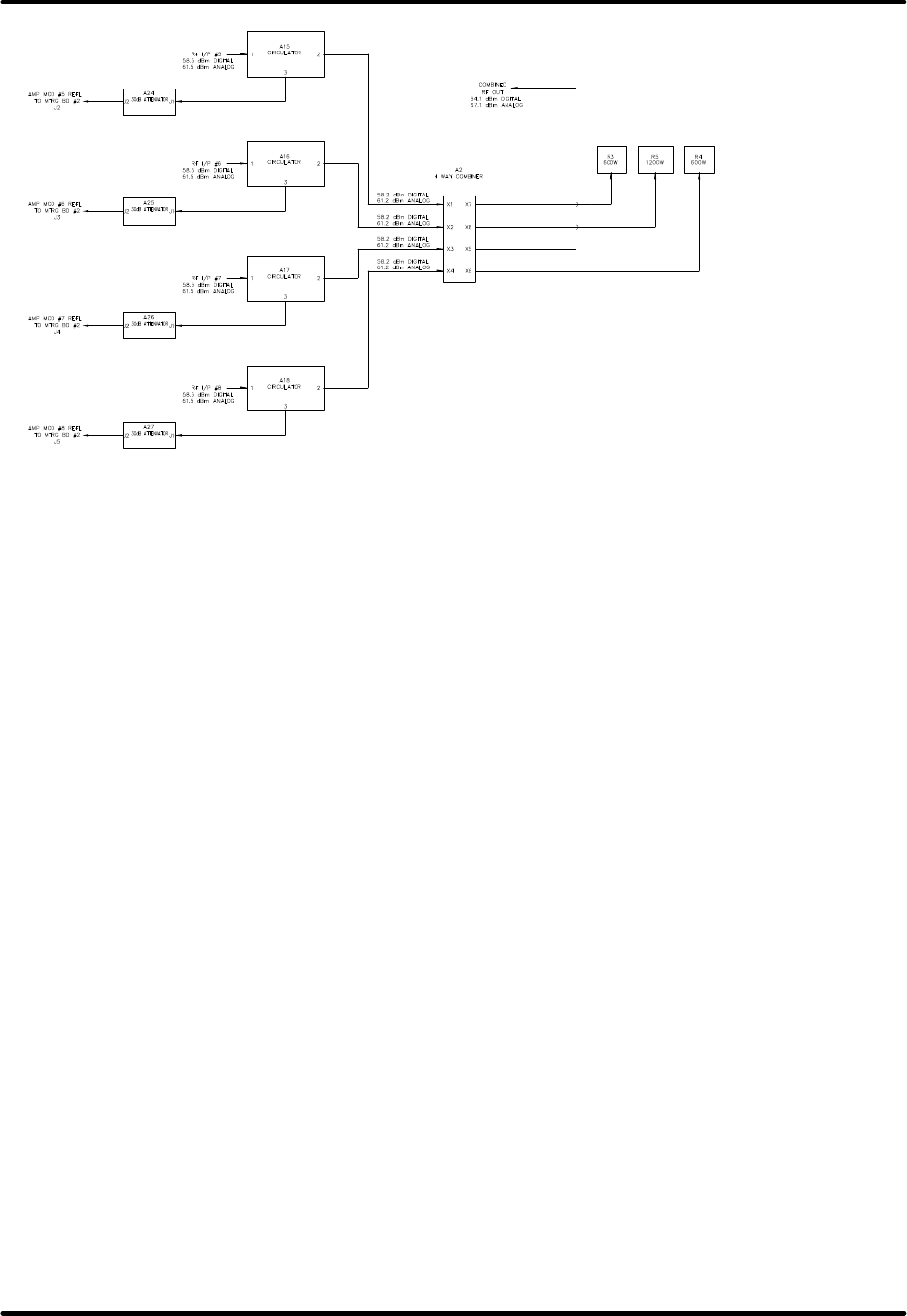
Figure 2-7: Block Diagram Typical 4 Way UHF Combiner Assembly w/Circulators
2.3.1.3: Description of the 3 Way
Combiner Assembly (1.8 kW
Amplifier Cabinet)
The RF outputs of the three amplifiers
are combined by means of a 3:1
combiner assembly that is mounted in
the middle of the cabinet.
The three RF inputs, +58.5 dBm Digital
in level, each connect to a separate
circulator. The circulators protect the
amplifiers in the event of high VSWR
generated by the output circuits. A
reflected sample from the circulator is
fed through a 30dB attenuator to the
Reflected Metering Board #2 (A81). If
one or more of the reflected samples
exceeds 10%, the Reflected Metering
Board will shut down the +32 VDC
power supply therefore removing the
voltages to the three amplifier
assemblies that it supplies. The power
supply can only be reset by switching
the transmitter to standby then operate
after repair of the cause for the high
VSWR. The 3 Way combiner has two
600W dummy loads, which dissipate any
power due to an imbalance or mismatch
during the combining of the amplifiers.
The output of the 3 Way Combiner
Assembly is at the 1 5/8” RF output
jack, typically ˜+62.6 dBm Digital.
2.3.2: Removal of an Amplifier
Assembly
The amplifiers are of broadband design
and cover the frequency for the desired
UHF channel without the need for
alignment or adjustment.
For reasons of safety, amplifier modules
MUST be in standby (RF disabled)
before any connections are removed. If
the amplifier control board is loaded
with software version 2.4 or higher, an
Axcera Amplifier disable plug (1308219)
can be used to place an individual
module in standby. If your amplifier
module has a front panel disable switch,
this switch can be used to disable the
amplifier. Regardless of the version of
code, any power amplifier may safely be
removed by disabling its power supply.
The power supply, either the top power
supply #1 for the top four Amplifier
assemblies, or the bottom power supply
#2 for the bottom three Amplifier
assemblies, may be isolated from main
AC power by switching off the
appropriate front panel circuit breaker.
This is accomplished by tripping the
respective breaker located on the circuit
breaker assembly panel, at the bottom
of the amplifier cabinet.

Innovator HX Series Digital Chapter 2, Amplifier Cabinet
UHF Transmitter
Volume 2, Rev. 0 2-9
To remove a disabled amplifier
assembly, first remove the input cable
connected to the top connector then the
output cable connected to the bottom
connector on the front panel of the
assembly. They must be removed in
this sequence to prevent damage to the
amplifier assemblies. Then loosen the
two fixing screws, one located at the
top, middle and one at the bottom,
middle of the assembly. The amplifier
can then be pulled from the cabinet. To
replace the assembly, insert the
assembly into the slots and replace the
two fixing screws. Then connect the RF
output cable first and the RF input cable
last, they must be replaced in this
sequence to prevent damage to the
amplifier assemblies.
The paralleling network of the amplifier
cabinet with its load balancing resistors
is designed so that operation continues
at reduced power when one or more
amplifiers are removed or failed.
All RF cables from the outputs of the
first splitter up to the output of the
output combiner assembly are phase
matched (in phase) to the particular
frequency and their lengths must again
be determined when a change in
operating frequency is made. All
amplifier cabinets of a transmitter, from
cabinet input to cabinet output, are also
aligned to the same phase with equal
length cables.
2.3.3: Amplifier Cabinet Power
Supply Assemblies
The voltages to the UHF Amplifier Trays
are supplied by two +32 VDC power
supply assemblies. One supply, the top
power supply #1, provides the +32 VDC
to the three or four UHF amplifier
assemblies mounted at the top of the
cabinet (3.7 or 5kW). The other supply,
the bottom power supply #2, provides
the +32 VDC to the three or four UHF
amplifier assemblies mounted at the
bottom of the cabinet (1.8 kW, 2.5 kW,
3.7 kW, & 5 kW).
The AC input voltages to the power
supplies are controlled through two 480
VAC 30 Amp 3 Phase or two 208 VAC 50
Amp 3 Phase circuit breakers located on
the AC distribution panel mounted at the
bottom of the cabinet (3.7 & 5 kW).
There is only one 480 VAC or 208 VAC
circuit breaker in a 1.8 & 2.5 kW
amplifier cabinet.
2.3.4: Control and Monitoring
Each amplifier has multiple-fault
protection circuitry that prevents
damage to or destruction of the power
transistors during critical operating
conditions, such as high reflected power,
overtemperature, overcurrent, or
overvoltage. Furthermore, the operating
voltages and currents of the amplifiers
are monitored in the power supply units
as well as the mains voltage. All
important amplifier operating
parameters, such as drain currents, RF
power, and heat sink temperatures, are
connected to the control unit.
2.3.5: Cabinet Cooling
The amplifier cabinet is exclusively air
cooled as shown in Figure 2-8. The
cooling system is exemplified by low
airflow requirements, low noise levels,
and high efficiency. With an inlet air
temperature of +25° C, the junction
temperatures of the RF power
transistors remain under 120°C,
resulting in a high amplifier service life.
A major fraction of the heat is dissipated
by the amplifiers and their power
supplies. This heat is carried away by an
external cooling system. Connections
are available on the top of the amplifier
cabinet for the intake and exhaust of the
air. The amplifiers are equipped with
highly efficient finned heat sinks, which
radiate, into the vertically flowing air
stream, the heat generated by the
power transistors. By utilizing special
construction techniques in the cabinet,
as well as employing conservatively
dimensioned ducting, a uniform
distribution of cooling air over the
Innovator HX Series Digital Chapter 2, Amplifier Cabinet
UHF Transmitter
Volume 2, Rev. 0 2-10
various heat sinks is achieved. This
ensures that all of the power transistors
are at essentially the same temperature.
Temperature test points connected to
special monitoring circuits are located in
the amplifiers and power supply units.
Under over temperature conditions, the
monitoring circuits respond and switch
off the respective unit. In addition, a
fault indication and the measured value
are passed to the control unit.
Control connections to the Blower is
through the terminal block TB1 located
at the rear upper right of the amplifier
cabinets. TB1-1 is +12 VDC and TB1-3
is Blower Control that connect to the Fan
Control in the Blower Cabinet.
Amplifiers
Example for the connection of air ducting to the roof of the cabinet
Amplifiers
Amplifiers
Amplifiers
Example for the connection of air ducting to the bottom of the cabinet
Figure 2-8: Air Flow in the Amplifier Cabinet
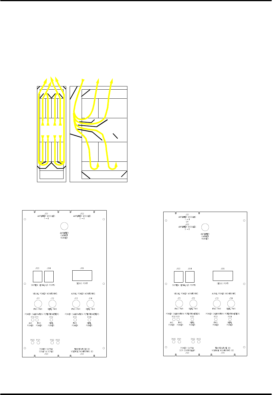
Figure 2-9A: Full Cabinet Controller
Assembly
Figure 2-9B: Half Cabinet Controller
Assembly

Innovator HX Series Digital Chapter 2, Amplifier Cabinet
UHF Transmitter
Volume 2, Rev. 0 2-11
2.4: Cabinet Controller Assembly
The Innovator HX cabinet controllers are
designed to control and monitor
components contained in the amplifier
cabinet. The cabinet controller is either
a full or half cabinet design as shown in
Figures 2-9A and 2-9B. A full cabinet
controller monitors and controls all
components of the amplifier cabinet
while a half cabinet controller monitors
and controls only half of the cabinet.
Two half cabinet controller assemblies
are used in single amplifier cabinet
configurations to give the transmitter
redundancy by allowing the top or the
bottom amplifiers to operate if the other
half cabinet controller assembly should
malfunction. When two half cabinet
controller assemblies are needed, they
are mounted on the power supply covers
in the rear of the amplifier cabinet. The
wire harness connection of J120 pin 8 is
used by the half cabinet controller to
determine if it is installed as an upper
half cabinet controller or a lower half
cabinet controller.
Status and control of each amplifier
cabinet is implemented through serial
commands that are transferred between
the transmitter's system controller and
the amplifier cabinet controller(s). Both
types of cabinet controller assemblies
contain two UARTs, Universal
Asynchronous Receiver-Transmitter ICs.
One of the controller’s UARTs is used
exclusively to communicate with
amplifiers within the cabinet. The
second UART provides status and control
of the cabinet to the transmitter's
control system. Serial debug port J108
is a standard read only RS-232 serial
port that is designed only for use with
Axcera factory test software.
Status and control of devices within the
amplifier cabinet is implemented
through discrete wired connections and
serial messages sent between the
amplifier control boards, located in the
individual amplifier modules, and the
cabinet controller(s).
The full cabinet controller obtains
+15VDC and -15VDC from one or two
switching power supplies located in the
lower front portion of the amplifier
cabinet. The half cabinet controller
obtains +15VDC and -15VDC from either
the top or bottom power supply
assembly in the amplifier cabinet
Cabinet controllers contain linear voltage
regulators that convert the +15 VDC to
+12 VDC. The +12 VDC power is
supplied to each of the amplifier
modules through self-resetting fuses.
The top and bottom high voltage power
supplies of the power amplifier cabinet
are regulated by SCR controllers located
in the lower front area of the cabinet.
The cabinet controller monitor the AC
supply voltage to the SCR controllers
and the health of the controllers. Half
cabinet controllers monitor the AC
supply to the upper or lower SCR
controller and the health of the specific
SCR controller.
Early systems used potentiometers
located in the cabinet controller
assembly to set the voltage output of
the high power supplies. Later systems
have the voltage level adjust
potentiometers located within the power
supply assembly. If voltage adjust
potentiometers are located within the
power supply, adjustment holes will be
visible through the rear cover of the
power supply assembly labeled, R120-
123.
RF power monitoring of the amplifier
cabinet is monitored through detectors
located on the cabinet controller board.
Separate aural and visual detectors are
available for externally diplexed
systems, however in earlier models of
the cabinet controller, the forward/visual
reflected power detection was obtained
using the aural reflected power port. In
systems with half cabinet controllers, RF

Innovator HX Series Digital Chapter 2, Amplifier Cabinet
UHF Transmitter
Volume 2, Rev. 0 2-12
samples are first split before they are
routed to each half cabinet controller.
Power amplifier modules mounted in the
amplifier cabinet are number referenced
in this document and the transmitter
control system from left to right and top
to bottom as observed from the front of
the amplifier cabinet. The number one
high voltage power supply is located in
the top of the amplifier chassis. It is
controlled by SCR #1, and circuit
protected by the left breaker located on
the power distribution assembly, in the
lower front of the cabinet. The High
voltage power supply number two is
located in the bottom of the amplifier
cabinet. It is controlled by SCR #2, and
circuit protected by the right breaker
located on the power distribution
assembly. Power supply one, top
supply, feeds amplifiers one through
four while power supply two, bottom
supply, powers amplifiers five through
eight.
2.4.1: Controller Connections to the
Transmitter's System Controller
Each cabinet controller has a unique
serial address that is determined by the
setting of a rotary switch that is
centrally located at the top of the
cabinet controller assembly. The RS-
485 serial address of the cabinet
controller is the switch position times
ten plus nine. I.E. Amplifier Cabinet
Number 1 uses serial address 19.
Serial messages between the cabinet
controller(s) and the transmitter's
system controller are transported over a
CAT-5 twisted pair cable using serial
ports J103 and J104. Either port can be
used as an input or output to the next
amplifier cabinet. The wiring of the
CAT-5 cables is a simple pin x to pin x
connection. If a replacement cable or
patch cable are needed, a simple
straight-thru Ethernet cable with two
RJ45 plugs can be used.
Table 2-1: Serial Cable Pin out
Pin Function
1 System Visual AGC #2
2 Ground
3 No Connection
4 System Serial +
5 System Serial -
6 No Connection
7 System Aural AGC #2
8 Ground
The CAT-5 cable is also used to
transport two analog reference voltages:
Aural AGC #2 and Visual AGC #2. Each
amplifier module produces a reference
voltage that is proportional to the power
output of the module. The amplifier
circuits and amplifier cabinet wiring are
configured such that the highest
measured reference voltage is selected
and wired to the amplifier cabinet
controller. The cabinet controller board
has circuitry that presents the highest
measured reference voltage to the
transmitter's system controller and
upconverter. In multiple amplifier
cabinet systems, the highest measured
amplifier reference voltage is the voltage
on the CAT-5 cable. In analog systems,
the aural amplifier reference voltages
are separate from the reference voltage
of the visual amplifier modules.
2.4.2: Controller Connections to
Amplifier Cabinet Components
2.4.2.1: Power Amplifiers
Power connections, serial connections
and reference voltage signals are sent
from the cabinet controller to each of
the amplifier modules through one of
two DB25 connectors. J101 is used to
interface through the amplifier wiring
harness to amplifiers one through four.
J102 is used to interface to amplifiers
five through eight.
Status and control of each amplifier
module is implemented through serial
messages sent between the amplifier's
control board and the cabinet controller

Innovator HX Series Digital Chapter 2, Amplifier Cabinet
UHF Transmitter
Volume 2, Rev. 0 2-13
assembly. The serial address of each
amplifier module is determined by the
wiring of the amplifier chassis. The
module knows which serial address to
use based on where it is located within
the system. The cabinet controller
board provides +12VDC and -12VDC to
each of the amplifier modules through
individual self-resetting fuses. The
+12VDC supplies of the first four
amplifiers are powered from one voltage
regulator (U14) that is supplied by
+15VDC. A separate voltage regulator
(U17) is used to power the +12VDC
lines of the last four amplifiers. U19 is
used to generate the -12VDC supply to
all of the amplifier positions.
Since some systems have separate aural
and visual power amplifiers, the chassis
wiring of position four and eight can be
wired for either an aural or a visual
amplifier. The reference AGC#2 voltage
of amplifier position four and eight is
wired through pin 22 of J101 / J102 in
digital systems or through pin 25 in
analog systems, where this amplifier
position is used for aural power
amplification. Amplifier modules are
enabled and disabled using a general
broadcast serial message. If an
amplifier does not properly receive the
message or for any other reason it is not
in the desired state, the controller will
individually command the amplifier into
the desired state.
2.4.2.2: High Power Supply
Controllers
The power amplifier high power supplies
of the amplifier cabinet are regulated
with SCR controllers located in the lower
front area of the cabinet. The cabinet
controller monitors the AC supply
voltage to the SCR controllers and the
health of the controllers. Early systems
used potentiometers located in the
cabinet controller to set the voltage
output of the high power supplies. Later
systems have the voltage level adjust
potentiometers located within the power
supply assembly. If the voltage adjust
potentiometers are located within the
power supply, adjustment holes are
visible through the rear cover of the
power supply assembly.
The amplifier cabinet wire harness
connects J120 of the cabinet controller
assembly to the power supply SCR
controllers. If the cabinet controller is
not enabled, the SCR controllers are
held Off with a logic low on position nine
of their terminal block. If the SCR
controller detects an output short, has
an over current fault, or is otherwise not
ready for operation, the specific SCR
controller is held Off. NOTE: Do not
remove power from the cabinet
controllers or disconnect J120 from the
cabinet controller with power applied to
the power amplifier high power supplies.
To allow the power supply to stabilize,
an amplifier module is not enabled until
five seconds after their associated high
voltage power supply has been enabled.
2.4.2.3: Low Power Supply and AC
Line Monitoring
The cabinet controller obtains its power
and power for operation of the amplifier
modules from a +15 VDC power supply
located in the lower front area of the
control cabinet. This supply also
contains a +5 VDC output, however this
supply tap does not have any significant
use. If redundant power supplies are
installed, the system will operate if only
one supply is operational. Diodes
located in the cabinet controller prevent
one supply from disabling the second
power supply. WARNING: THE HIGH
VOLTAGE SUPPLY LINES ARE ALSO
LOCATED BEHIND THE FRONT COVER.
REMOVE POWER FROM THIS AREA BY
LOCKING OUT THE HIGH VOLTAGE
FEEDS TO THE AMPLIFIER CABINET.
The cabinet controller obtains AC line
monitoring samples from a circuit board
located in the front of the amplifier
chassis. These signals are line to

Innovator HX Series Digital Chapter 2, Amplifier Cabinet
UHF Transmitter
Volume 2, Rev. 0 2-14
ground samples obtained by resistor
dividers. Two unique board assemblies
are used: one for systems that operate
around 220VAC input and another for
systems that are operating around
440VAC. An internal DIP switch located
on the cabinet controller board is used
to scale the input values from the AC
monitoring board. Switch 2 position
four needs to be OFF for 220 VAC
systems and ON for 440 VAC systems.
When a system is configured to operate
around 220 VAC, a phase loss fault is
generated if one or more input phases
measure less than 176 VAC. For
systems operating around 440 VAC, a
phase loss fault is generated if one or
more input phases measure less than
353 VAC.
2.4.2.4: Air Temperature and
Amplifier Temperature Monitoring
The amplifier cabinet inlet air
temperature is monitored by a
thermistor located in the cabinet
controller. A small remote circuit board
is used to monitor the exhaust
temperature of the amplifier chassis.
The exhaust temperature is measured in
the front top center of the amplifier
chassis. At this time, neither the inlet
air temperature nor exhaust air
temperature is used for fault detection.
A cabinet cooling fault is only generated
by the detection of an over temperature
fault in two or more modules of the
amplifier chassis. If an over
temperature fault occurs, all amplifiers
are placed in standby and the fault is
latched. The fault is only cleared when
the amplifier cabinet is placed into
standby mode.
2.4.2.5: RF Power Monitoring
The separate amplifiers modules of the
cabinet are combined prior to connection
to couplers that measure the cabinet's
RF output power. Separate aural and
visual detectors are available, however
in early models of the cabinet controller,
visual reflected power detection was
implemented using aural reflected power
port J114 instead of J112. Please refer
to cabinet controller settings section, for
proper setting of the DIP switch two
position five.
Sample ports are available to monitor
the RF output energy and the energy
reflected back into the cabinet. Digital
systems monitor forward power on J111
and reflected power on J112. In analog
systems, the aural forward power is
measured on J113, the visual forward
power detection uses J111, and the
visual reflected power is measured using
J112. If an aural system is externally
diplexed, the aural reflected power is
monitored using J114.
Table 2-2: Cabinet Controller DIP Switch Settings
Switch
Number Function Position Normal
Operating
Position
SW2-1 Reserved for Factory Test 0 = Off
1 = On Off - Must be Off
SW2-2 Allow Power Supply Enable on
Cooling FLT 0 = Off
1 = Allow Off - Must be Off
SW2-3 Allow Power Supply Enable on
RFL PWR FLT 0 = Off
1 = Allow Off
SW2-4 High Voltage Supply Range 0 = 220
1 = 440 System
dependent
SW2-5 Reflected Power RF Source 0 = J112
1 = J114 (If not
Externally Diplexed) System
dependent

Innovator HX Series Digital Chapter 2, Amplifier Cabinet
UHF Transmitter
Volume 2, Rev. 0 2-15
Switch
Number Function Position Normal
Operating
Position
SW2-6 Allow Power Supply Enable on
Reject Load Faults 0 = Off
1 = Allow Off
SW2-7 Reserved for Factory Test 0 = Off
1 = On Off - Must be Off
SW2-8 Reserved for Factory Test 0 = Off
1 = On Off - Must be Off
NOTE: These switch positions are factory set and should not be changed.
2.4.2.6: Reject Load Monitoring
Select UHF amplifier systems require the
use of circulators within the amplifier
cabinet combiner. The reject loads of
these circulators have a limited power
rating therefore the energy into these
loads is monitored. NOTE: VHF
amplifier modules do not require
circulators thus reject load monitoring is
not required.
J120 Pin 10, on the amplifier cabinet
controller, is used to monitor a signal
that is proportional to the highest reject
load energy of amplifier positions one
through four. Pin 13 is used to monitor
the highest reject load energy of
amplifier positions five through eight.
If the reject load voltage of a set of
amplifiers exceeds a preset that is
typically 0.8 VDC, the power supply of
the associated amplifiers and the
amplifiers themselves will be disabled.
NOTE: Reject load faults can only be
cleared by placing the amplifier cabinet
in standby.
2.4.3: Cabinet Controller Settings
Within the cabinet controller assembly is
an eight position DIP switch, SW2 that is
used to enable select features. See
Table 2-2.
2.4.4: Cooling Blower Control
The cabinet controller board provides
signals that can be used to operate a
cabinet cooling blower relay. On the
board, Pin 16 provides +5VDC through a
0.5 amp self-resetting fuse. J125 pin
20, on the board, provides an open-
drain connection for cabinet cooling
blower control. Pin 19 provides +12VDC
through a 0.5 amp self-resetting fuse.
These two connections are wired to the
Terminal Block TB1 located in the rear,
right side, near the top of the amplifier
cabinet. TB1-1, +12VDC, and TB1-3,
Blower Control, need to be connected by
22AWG wire to the Fan Control Board
mounted in the blower cabinet to
operate the Blower. NOTE: If multiple
cabinets are connected to one blower
relay, diodes need to be added to the
+12V and +5V lines for isolation of the
cabinet power supplies. When the
cabinet is enabled, the drain of the FET
connected to J125 pin 20 is pulled low to
ground. Use this signal to control the
DC coil of a cooling blower relay.

Innovator HX Series Digital Chapter 2, Amplifier Cabinet
UHF Transmitter
Volume 2, Rev. 0 2-16
2.4.5: Cabinet Controller Problem Resolution Guide
Table 2-3: Cabinet Controller Assembly Problem Resolution Guide
Condition Possible Cause
Transmitter is
enabled but either
the Amplifier(s) and
or the Power
Supplies are not
enabled.
• One of the three AC input phases may not be present or at least
one may be low in voltage.
• Serial communication with the cabinet controller may not be
operational thus, the amplifiers and power supplies are remaining
in their last state.
• Reject load levels of an UHF system may be greater than the
programmed fault threshold.
• If two or more amplifier modules report an over temperature
condition, all amplifiers are placed into standby and the fault is
latched until the cabinet is placed into standby mode.
• High voltage power supply SCR controller(s) may not be
operational.
• Amplifiers are not enabled until the power supplies are enabled for
five seconds.
• Cabinet Controller internal DIP switch position one may be in the
on position. This position causes the controller to ignore serial
communication commands thus the amplifiers and power supplies
are remaining in their last state.
All LEDs of
Amplifier Modules
are Off.
• If tripped, reset the 110 VAC circuit breaker(s) of the +15 VDC
supply(s) located in the lower front of the control cabinet. If
redundant power supplies are installed, the system will operate if
only one supply is operational. Diodes located in the cabinet
controller prevent one supply from disabling the second power
supply.
• Determine if the +15 VDC supply located in the lower front of the
control cabinet has valid input and output levels. WARNING:
THE HIGH VOLTAGE SUPPLY LINES ARE LOCATED BEHIND THE
FRONT COVER. REMOVE POWER FROM THIS AREA BY LOCKING
OUT THE HIGH VOLTAGE FEEDS TO THE AMPLIFIER CABINET.
• Disconnect and pull each amplifier module forward a few inches to
disengage it from the supply connector. Determine if one
amplifier may be the source of the problem. Each amplifier is
powered through a self-resetting 0.5 amp fuse.
Innovator HX Series Digital Chapter 2, Amplifier Cabinet
UHF Transmitter
Volume 2, Rev. 0 2-17
Table 2-3: Cabinet Controller Assembly Problem Resolution Guide - Continued
Condition Possible Cause
Amplifier
Module
Status LED
is blinking.
(LED located
nearest to
the amplifier
handle.)
• The module status LED is blinked to show various fault states:
Blinks Fault Type
1 Pallet(s) Over Current 3 Fault w/ 5 second min and 5 Minute
Retest
2 Over Temperature 1 Fault with 5 Minute Retest
3 High Power Supply Over
Voltage 1 Fault without retest. Requires
standby to clear.
4 High Power Supply
Under Voltage 3 Fault w/ 5 second min and 5 Minute
Retest
5 Reflected Power Fault 3 Fault w/ 5 second min and 5 Minute
Retest
6 +12 VDC Supply Fault Faulted only while supply is out of
range
7 Overdrive Fault 3 Fault w/ 5 second min and 5 Minute
Retest
Notes: 3 Fault means that if the fault occurs three times within 30 seconds,
the fault is latched.
A 5 Minute Retest means that the fault is held active for five minutes.
After five minutes, the fault is cleared and the amplifier is re-enabled.
If the amplifier module is placed in standby, fault counters and
latched states are immediately cleared thus allowing the system to
return to operate mode.
Amplifiers or
Cabinet
Controller
not
reporting on
transmitter's
System
Controller
• Verify amplifier module is fully seated in amplifier chassis.
• If entire amplifier cabinet is not responding, check serial cable between
the amplifier cabinet and transmitter system controller.
• If multiple amplifier cabinets are present, disconnect cable from first
amplifier cabinet to second cabinet. If communication resumes,
reconnect the serial cable and remove the next amplifier cabinet serial
cable. Continue through the system until the source of communication
error is identified.
• Exchange amplifier module with another position in the system. If the
error travels with the amplifier module, it needs serviced. If the error
remains in the same position, either the amplifier cabinet wire harness
has been damaged or the cabinet controller board has been damaged. If
the problem does not return when the amplifier modules are exchanged,
a software update may be needed for either the cabinet controller or the
amplifier module(s).
• Does amplifier respond to serial operate and standby commands. If so, a
software update may be needed for the amplifier module(s).
Cabinet
Controller
reports a
reflected
power fault.
• Verify that the cabinet reflected power fault threshold is not set too low.
• If possible, use J114 for visual reflected power fault monitoring. This
problem should only occur on cabinet controller boards 1305306 version A
and B.

Innovator HX Series Digital Chapter 2, Amplifier Cabinet
UHF Transmitter
Volume 2, Rev. 0 2-18
2.5: Functional Description of the
Amplifier Cabinet
2.5.1: Signal Path
The RF signal delivered by the exciter
(+27 dBm) is connected through RG-55
cable to the amplifier cabinet and
distributed to the inputs of the power
amplifiers (PAs) through one 1:2
splitter, then two 3 or 4 way splitter
panels. The top 3 or 4 way panel
supplies the RF to the top 3 or 4
amplifier trays and the bottom 3 or 4
way panel supplies RF to the bottom 3
or 4 amplifier trays.
The power amplifier tray is a three-stage
design comprised of a predriver (≈9 dB
gain), a driver (≈13 dB gain), and the
final stage (≈21 dB gain). The RF signal
(≈18 dBm) is first preamplified in the
predriver (≈24 dBm) and driver (≈37
dBm) before it is passed through a
coupler board to the splitter where it is
split four ways (≈34 dBm) and
distributed to the four final-stage
modules. The outputs of the final stages
(≈55 dBm) are summed in a combiner.
The output of the combiner (≈58.6 dBm)
connects to a directional coupler that
couples out voltages proportional to the
forward power at the output of the
amplifier, as well as a voltage
proportional to the reflected power at
the output of the amplifier. The output
of the amplifier tray is typically +58.5
dBm. The coupler also provides a signal
proportional to the forward power at the
output of the amplifier that is passed to
J3 on the front panel to provide an RF
sample for test purposes. The same
coupler also supplies a voltage
proportional to the forward power from
the driver stage, which is used in the
monitoring and control circuitry. In
addition, the reflected power at the
amplifier output is monitored in the
control board of the amplifier and, if the
set threshold value is exceeded, the
operating voltages for the predriver and
driver are switched off and a fault
indication of the high reflected condition
is stored.
2.5.2: Test Signal Evaluation
The RF samples test voltages are passed
to the control board of the amplifier for
internal evaluation and partly for
interrogation by the control unit. The
test values for the forward power at the
amplifier outputs are passed to the
control unit.
The following test points are available
for external measuring equipment or
transmitter control equipment:
• RF test point at the amplifier outputs
at “N” connector (J3).
• RF test points at the output side of
the amplifier through (A41) a
directional coupler downstream of
the cabinet combiner.
2.5.3: Regulation of Transmitter
Output Power
The regulation of output power takes
place in the Digital Exciter. The actual
value for the automatic level control
(ALC) is taken from test voltages in the
amplifiers that are dependent on the
output power.
If an amplifier fails, transmitter
operation continues at reduced power.
In order to prevent the ALC from
correspondingly increasing the output
power of the Digital Exciter during
reduced power operation, the test
outputs of the individual amplifiers are
circuited in parallel so that only the test
voltage of the amplifier that delivers the
highest output power is used in the
control loop.
2.5.4: Fault Protection Circuitry
The amplifiers possess fault protection
circuitry, which, if necessary, initiates
the switching Off, of the respective unit
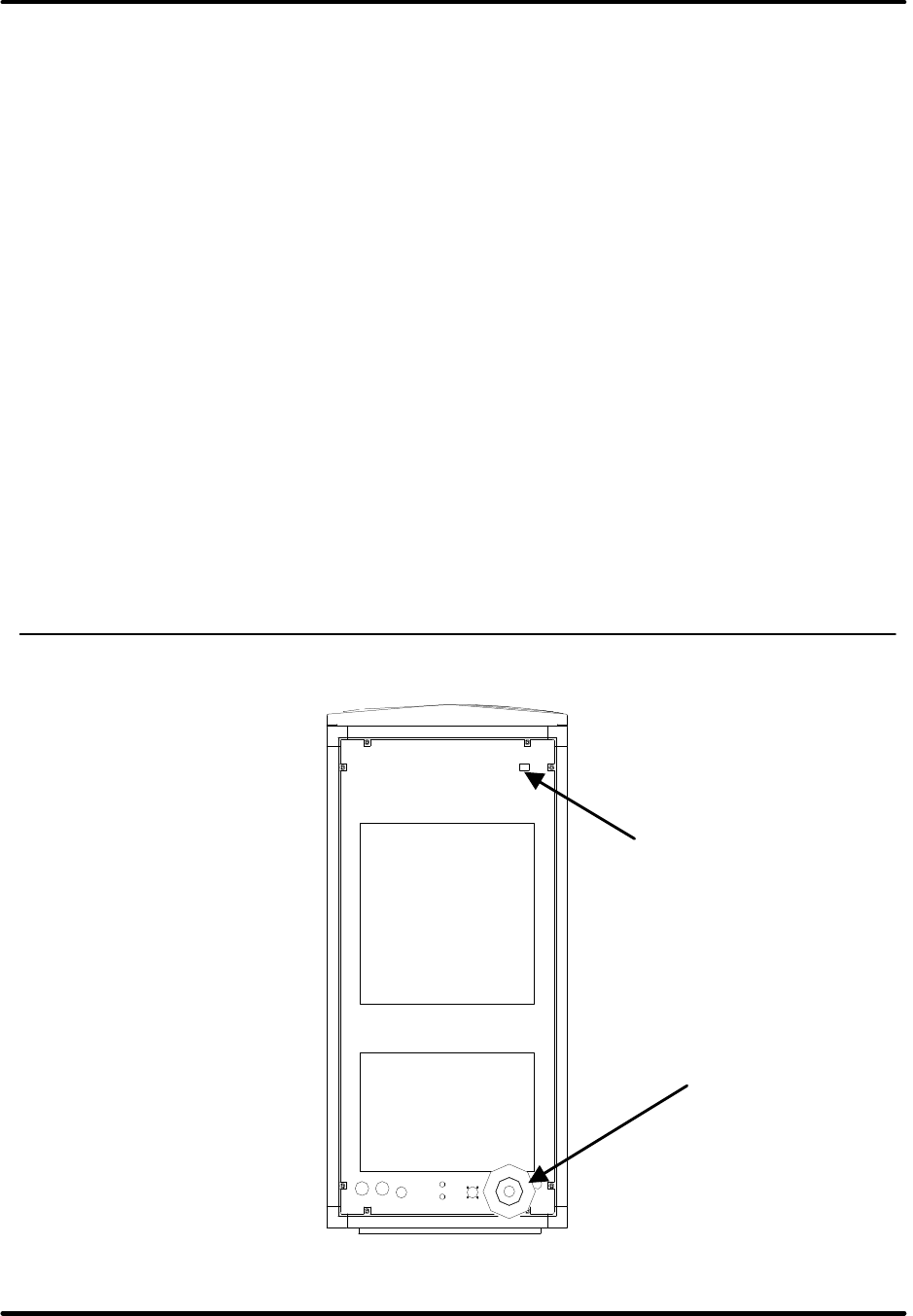
Innovator HX Series Digital Chapter 2, Amplifier Cabinet
UHF Transmitter
Volume 2, Rev. 0 2-19
and simultaneously issues a fault
indication to the control unit.
The protective circuits in the amplifiers
monitor the following values:
• Drain currents of the final stage
transistors
• Operating voltage
• Temperature
• Reflected power at the output
If a threshold value is exceeded, the
amplifier shuts down. Following a one-
off fault, the amplifier automatically
switches on again after a delay of about
1 second. When repeated faults occur
(more than 5 within 10 seconds), the
amplifier switches on again after a delay
of 5 minutes. In addition, the amplifier
can be switched on, at any time, by a
command from the transmitter control.
The protective circuits in the power
supply units monitor the following
values:
• 480/208 VAC Mains voltage
• 480/208 VAC Mains phase
• Primary voltage
• Primary current
• Output voltage
• Temperature
2.5.5: Capture of Operating Values
in the Amplifiers
The following operating values are
captured and processed in the amplifier
control board and prepared for
transmission to the exciter/control
cabinet controller.
• Drain currents of the final-stage
transistors
• Operating voltage
• Temperature
• Forward power at the output
• Reflected power at the output
2.5.6: Amplifier Cabinet Connections
Figure 2-10: Amplifier Cabinet Connections
RF Output
3-1/8” EIA
RF Input to S Input on the
(A14) 2 Way Splitter
(1.8kW or 5kW) or to the
X5 input jac
k on the (A16)
4 Way Splitter Panel
(2.5kW) or (A16) 3 Way
Splitter Panel (1.8kW)
Innovator HX Series Digital Chapter 2, Amplifier Cabinet
UHF Transmitter
Volume 2, Rev. 0 2-20
Table 2-4: Amplifier Cabinet Connections
Connector Assignment Type
S on (A14) 2 Way Splitter (1.8kW or 5kW) or to the
X5 input jack on the (A16) 4 Way Splitter Panel
(2.5kW) or (A16) 3 Way Splitter Panel (1.8k) RF Input RF SMA-type
female connector
RF O/P of (A25) Combiner RF Output 3-1/8 EIA
2.6: Service
The amplifier cabinet is user-friendly and
designed for operational safety. The
paralleling networks in the cabinet
ensure that if an amplifier fails or is
removed, transmitter operation
continues at reduced power without
degradation of performance.
The amplifiers are factory aligned and
can be inserted in the cabinet without
the need for retuning or adjustment.
2.6.1: Safety Information
The amplifier cabinet is maintenance
free; however, in order to ensure
trouble-free operation, it must be
checked and serviced at regular
intervals, taking into account the local
environmental conditions. Operational
reliability depends on proper service.
This is especially relevant when checking
grounding and power connections.
Work on the amplifier cabinet must only
be performed by trained personnel. Take
note of the following precautions:
• Before working on or removing a
component, make sure that it is
isolated from power.
• Carry out all work with extreme
caution.
2.6.1.1: Labeling of Dangerous
Substances
Components containing substances
dangerous to health are labeled as such.
The label is either glued on the
component itself or in its immediate
vicinity.
In drawings (e.g., component layouts of
PC boards) and circuit diagrams, parts
containing toxic substances, such as
beryllium oxide (BeO), are labeled as
shown in Figure 2-11.
BeO
B e r y l l i u m o x i d
Figure 2-11: Labeling of Toxic
Substances in Drawings
2.6.2: Test Point Evaluation
Various RF test points in the signal path
in the amplifier cabinet are available for
evaluation and can be polled and
displayed through the control unit. RF
test points for external measuring
equipment are also available at the
amplifiers and the directional coupler at
the output of the amplifier cabinet.
2.6.3: Display of Operating Values
Aside from RF powers, the following
operating values can be polled and
displayed in the transmitter control unit:
• Forward & Reflected power at the
output of the amplifiers
• Amplifier operating voltage
• Amplifier currents
• Amplifier temperatures
• Forward power at the output of the
amplifier cabinet
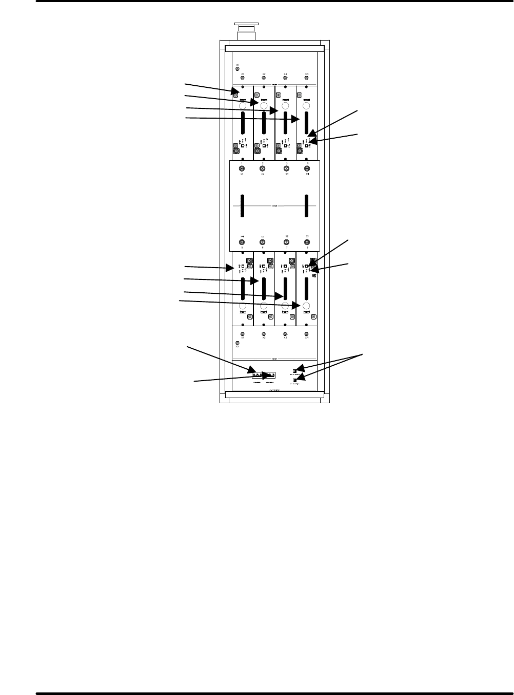
Innovator HX Series Digital Chapter 2, Amplifier Cabinet
UHF Transmitter
Volume 2, Rev. 0 2-21
Figure 2-12: Location and Assignment of the Circuit Breakers and LEDs
2.7: Exchange of an Amplifier
Module
For reasons of safety, amplifier modules
MUST be in standby (RF disabled)
before any connections are removed. If
the amplifier control board is loaded
with software version 2.4 or high, an
Axcera Amplifier disable plug (1308219)
can be used to place an individual
module in standby. If your amplifier
module has a front panel disable switch,
this switch can be used to disable the
amplifier. Regardless of the version of
code, any power amplifier may safely be
removed by disabling its power supply.
The power supply, either the top power
supply #1 for the top four Amplifier
assemblies, or the bottom power supply
#2 for the bottom four Amplifier
assemblies, may be isolated from main
AC power by switching off the
appropriate front panel circuit breaker.
This is accomplished by tripping the
respective breaker located on the circuit
breaker assembly panel, at the bottom
of the amplifier cabinet.
Disconnect the RF cables. NOTE: To
prevent damage to the module, first
disconnect the Input Cable and then
disconnect the Output Cable.
Undo the two holding, fixing, screws and
pull the amplifier out to the end stop.
Find and release the mechanical lock,
AMP#1 A17 (PS#1)
AMP#2 A18 (PS#1)
AMP#3 A19 (PS#1)
AMP#4 A20 (PS#1)
AMP#5 A21 (PS#2)
AMP#6 A22 (PS#2)
AMP#7 A23 (PS#2)
AMP #8 A24 (PS#2)
POWER SUPPLY #1 CIRCUIT
BREAKER FOR TOP AMPLIFIERS
POWER SUPPLY #2 CIRCUIT
BREAKER FOR BOTTOM AMPLIFIERS
MODULE OK LED
ENABLE LED
ENABLE LED
MODULE OK LED
±12V POWER SUPPLY
RESET BREAKERS
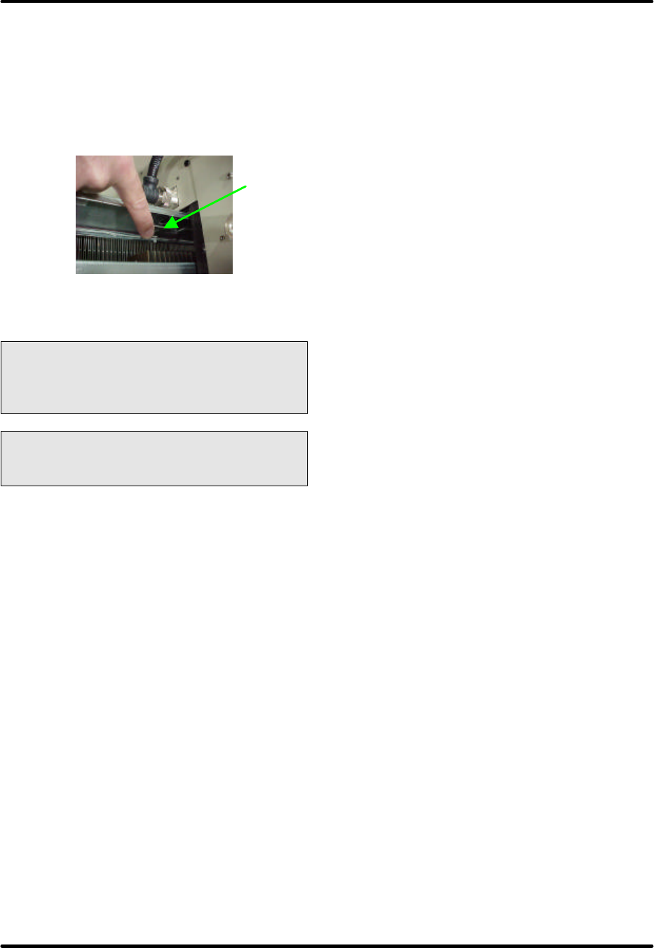
Innovator HX Series Digital Chapter 2, Amplifier Cabinet
UHF Transmitter
Volume 2, Rev. 0 2-22
located on the bottom of the top four
amplifier trays and on the top of the
bottom four amplifier trays. See Figure
2-13. Pushing the release down on
bottom amps and up on top amps
releases the catch. Pull the amplifier
completely out of the cabinet assembly.
Figure 2-13: Amplifier Tray Lock
Location
Caution: The amplifier weighs
approximately 60 pounds. Use
extreme care when removing it from
the cabinet.
Caution: After the amplifier is pulled
out, a high voltage may still be
present at its output.
Insert and secure the new amplifier.
Note the vertical position of the amp
tray, do not try to insert upside down.
Carefully push the amplifier into the rear
connectors making certain that solid
connection is made.
NOTE: If a replacement amplifier is not
available, then the Air Blocking Plate
should be installed in the slot where the
amplifier assembly was removed and a
fake front panel should be installed on
the cabinet. This is to insure proper air
flow through the cabinet and cooling of
the remaining amplifier trays.
Connect the RF cables. NOTE: First
connect the Output Cable and then
connect the Input Cable.
Engage the respective circuit breaker,
Power Supply #, 1 for amplifiers (1-4,
A17-A20) or Power Supply #2, for
amplifiers (5-8, A21-A24).
Amplifier Adjustments
There are no customer adjustments.
Information on a Change of Channel
Frequency
The following work must be carried out
at the amplifier cabinet when changing
the channel frequency:
• The length of RF cables between the
splitters and the amplifiers have to
be altered.
• The coupling attenuation needs to be
checked.
• The output powers of the amplifiers
must also be checked.
NOTE: It may be necessary to make
further adjustments at other cabinets
and assemblies in the transmitter when
a change in channel frequency is made.
Lock
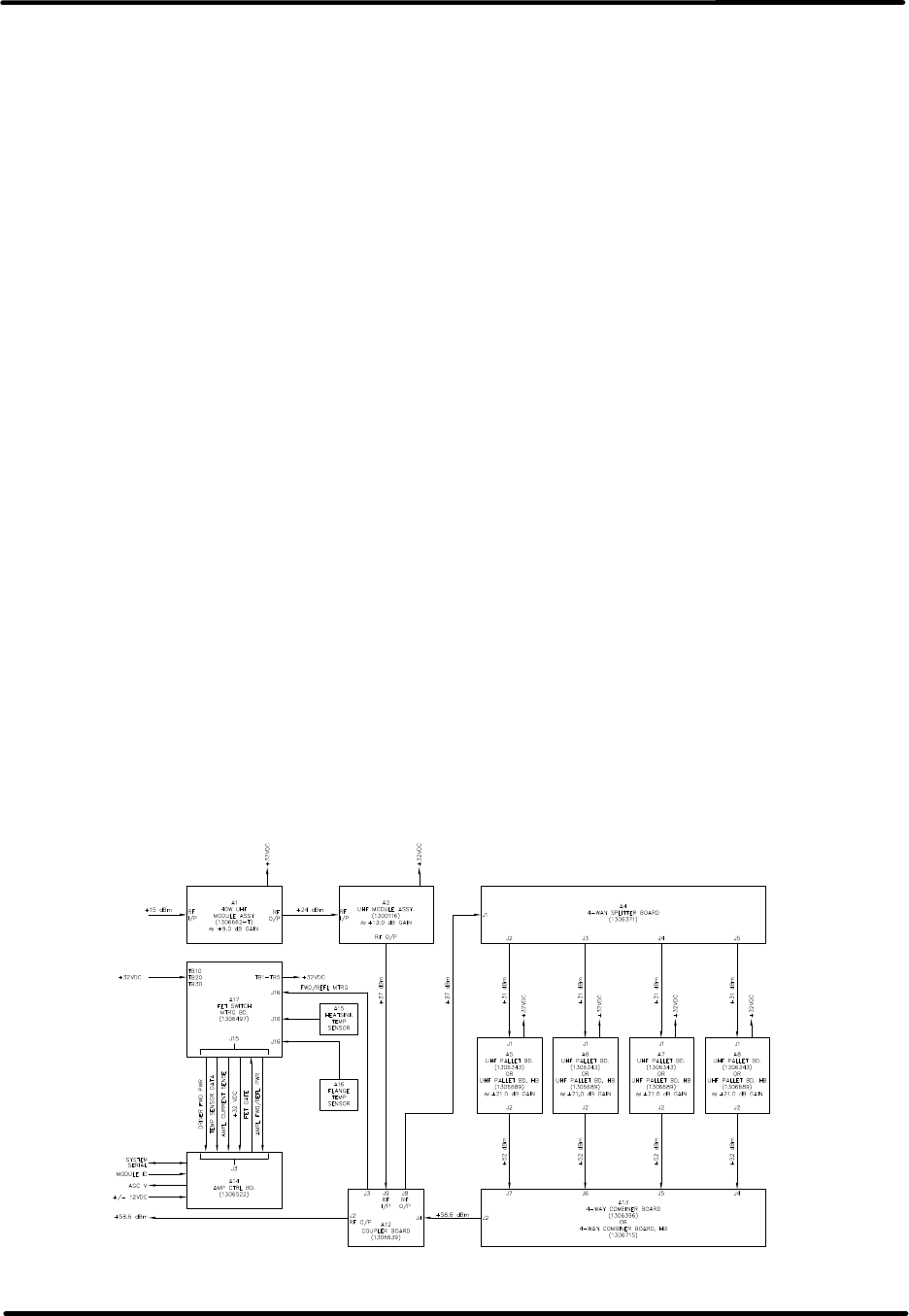
Innovator HX Series Digital Chapter 3, UHF Amplifier Assembly and
UHF Transmitter Cabinet Assemblies Circuit Descriptions
Volume 2, Rev. 0 3-1
Chapter 3
UHF Amplifier Tray Assembly and Cabinet Assemblies
Circuit Descriptions
3.1: Amplifier Overview
Each UHF amplifier tray assembly serves
to amplify the RF signal delivered by the
exciter to the power level needed to
attain the full rated output power of the
transmitter. Nominal transmitter output
power is achieved by adding the parallel
connection of individual amplifier
assemblies, within a cabinet assembly,
and then the adding of a number of
multiple amplifier cabinet assemblies.
The amplifier operates over the portion
of the UHF Low, Medium or High Band
TV frequency spectrum without any
special tuning requirements. It is a
three-stage amplifier design formed by a
predriver, driver, and final stage as
shown in Figure 3-1. The driver is a
single stage amplifier module whose
output is split four ways. The final stage
is made up of four identical power
modules. The four outputs are
connected to a 4-way combiner
assembly whose output is the RF output
of the individual amplifier assembly.
The features of the UHF amplifier
assembly include:
• All amplifying stages are equipped
with transistors
• Operates over the designated portion
of the UHF frequency band without
special tuning requirements
• High redundancy due to the parallel
connection of many power transistors
• Mean junction temperature <120° C
• Important operating parameters
displayed in the transmitter control
assembly
• Multiple fault protection circuitry
against mismatch, overvoltage,
overcurrent and overtemperature
conditions
The amplifier possesses multiple fault-
protection circuits that prevent damage
to the power transistors during critical
operating conditions, such as high
mismatch, overtemperature,
overcurrent, or overvoltage. Important
operating parameters, such as drain
currents, operating voltages, RF powers,
and temperatures are polled and
displayed in the transmitter control
assembly.
Figure 3-1: UHF Amplifier Assembly
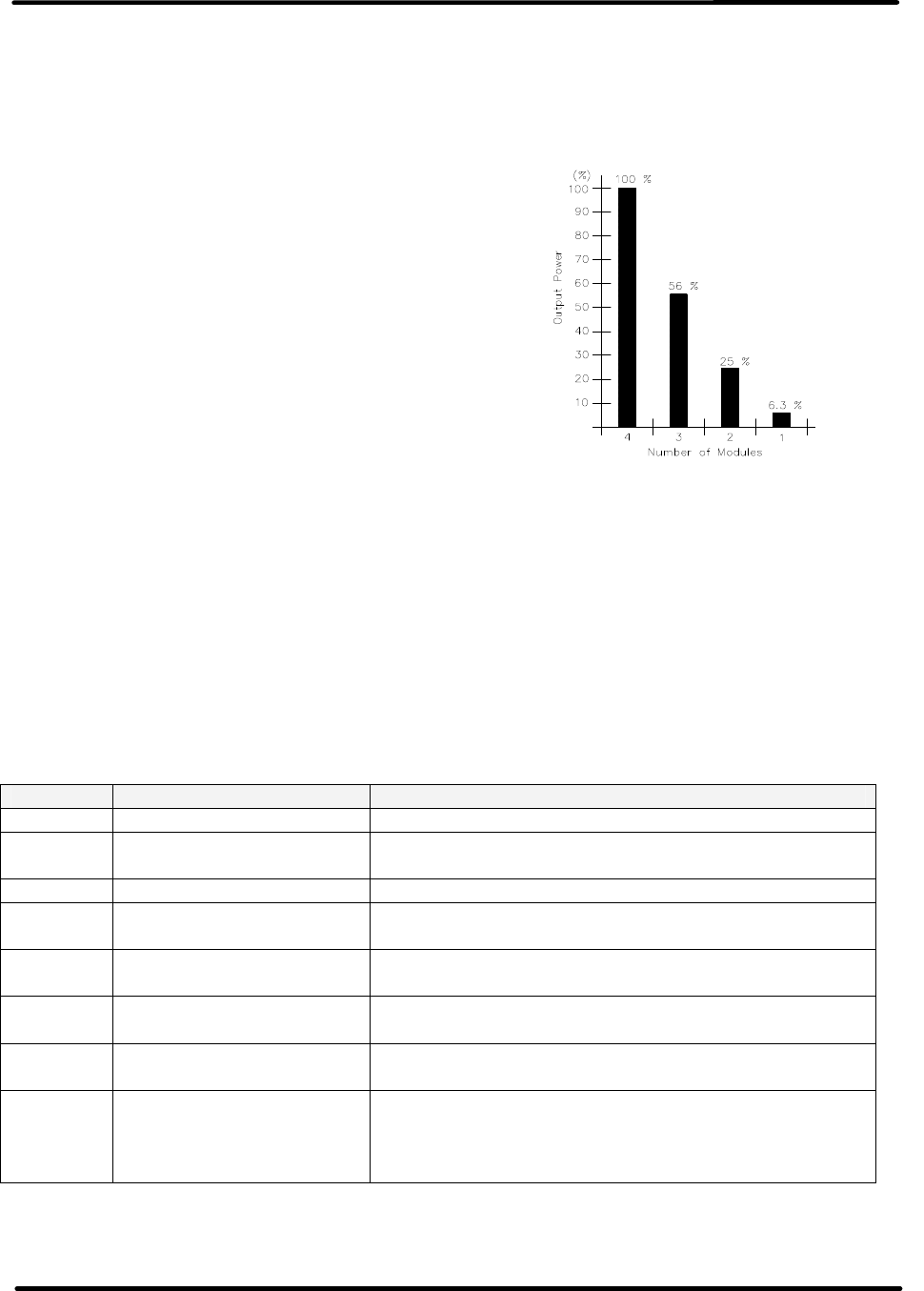
Innovator HX Series Digital Chapter 3, UHF Amplifier Assembly and
UHF Transmitter Cabinet Assemblies Circuit Descriptions
Volume 2, Rev. 0 3-2
The paralleling network of the amplifier is arranged so that it continues to operate at
reduced power if a module fails. The remaining available power is given by:
Prem = Pnom ⋅ ([m - n] / m)2
where:
Prem = remaining power
Pnom = nominal power
m = number of modules
n = number of failed modules
Figure 3-2: Remaining Power after Failure of Amplifier
Modules
3.2: Design of the UHF Amplifier
The amplifier is designed as a slide-in
unit. The mechanical support structure is
formed by a finned heat sink on which
the individual assemblies are mounted.
The amplifier assemblies are listed in
Table 3-1.
All RF connectors are located on the
front panel, while the control and power
connectors are mounted at the rear. The
control board is mounted behind the
front panel. Two LEDs on the control
board (visible through the front panel)
signal the operating status of the
amplifier, Module OK and Enable LEDs.
Table 3-1: Assemblies in the UHF Amplifier
Position Assembly Remarks
A14 Amp Control Board For control, monitoring, and test signal capture
A1 40 Watt UHF Module
Assembly Predriver (≈9 dB gain)
A2 UHF Module Assembly IPA, Driver, to the splitter (≈13 dB gain)
A12 Coupler Provides Driver forward, and final amplifier
forward an reflected power samples
A4 Splitter (1:4) Distributes the RF input power to the final
amplifier boards A5 to A8. (≈34 dBm)
A5 to A8 UHF Dual Stage Pallet
Boards Four final amplifier boards (≈21 dB gain)
(≈55 dBm O/P)
A13 Combiner (4:1) Sums the output powers of the 4 UHF Pallet
Boards. (≈58.6 dBm Output)
A17 FET Switch/Metering
Board
Takes the three +32VDC inputs and switches
them to the predriver, driver and the amplifier
pallets. In addition, the metering samples
connect through the board.
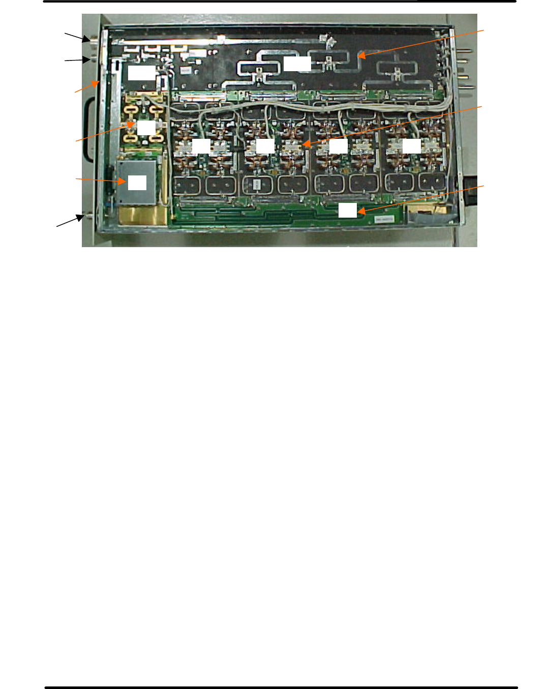
Innovator HX Series Digital Chapter 3, UHF Amplifier Assembly and
UHF Transmitter Cabinet Assemblies Circuit Descriptions
Volume 2, Rev. 0 3-3
Figure 3-3: Location of the Assemblies in the UHF Amplifier
The amplifier is a three-stage design
with a 40 Watt UHF low level predriver,
a UHF module single amp driver and
four UHF pallet final amplifier stages.
The RF input signal (+18 dBm) is fed to
the amplifier through connector J1 on
the front panel. The signal is
preamplified by the 40W UHF module
assembly A1 (predriver) (+27 dBm),
amplified by the UHF single stage
module A2 (driver) (+40 dBm) before it
is passed through A12 the coupler
assembly to the 4 way splitter A4 (+40
dBm). The outputs (+34 dBm) are
distributed to the four UHF dual final
stage modules A5 to A8. The outputs of
each of the final stage modules (+55
dBm) are combined in the 4 way
combiner A13 and the resultant signal is
passed to RF output connector J2
(≈+58.5 dBm).
The predriver and the 4 way combiner
incorporate the A12 directional coupler
to supply output voltages proportional to
the forward powers at the input to the 4
way splitter and at the output of the 4
way combiner. They also couple out
voltages proportional to the reflected
power at the output of the 4 way
combiner. These test voltages are
passed to the amp control board,
mounted, behind the front panel, for
internal evaluation and partly for
interrogation by the control unit. In
addition, the reflected power at the
amplifier output is monitored in the
control board and, if the threshold value
is exceeded, the operating voltages for
the predriver and driver are switched off
and a fault indication is stored. A
directional coupler in the combiner also
couples out a signal proportional to the
forward power at the output of the 4
way combiner. This signal is passed to
connector J3 on the front panel to
provide the RF test signal.
Test voltages derived from the forward
power of the amplifier are generated in
the amp control board to provide
automatic level control (ALC) in the
exciter stage of the transmitter. The
ALC is a function of the rms value of the
output power.
A13 4 Way
Combiner
Board
A8
A7
A6
A5
A5, A6,
A7, A8
UHF Pallet
Boards
A4 4 Way
Splitter
Board
J1
RF Input
J2
RF Output
A2 UHF
Module
Assembly
A13
A12
A2
A1
A4
A1 40W
UHF Module
Assembly
A14
Amp Control
Board
J3
RF Sample
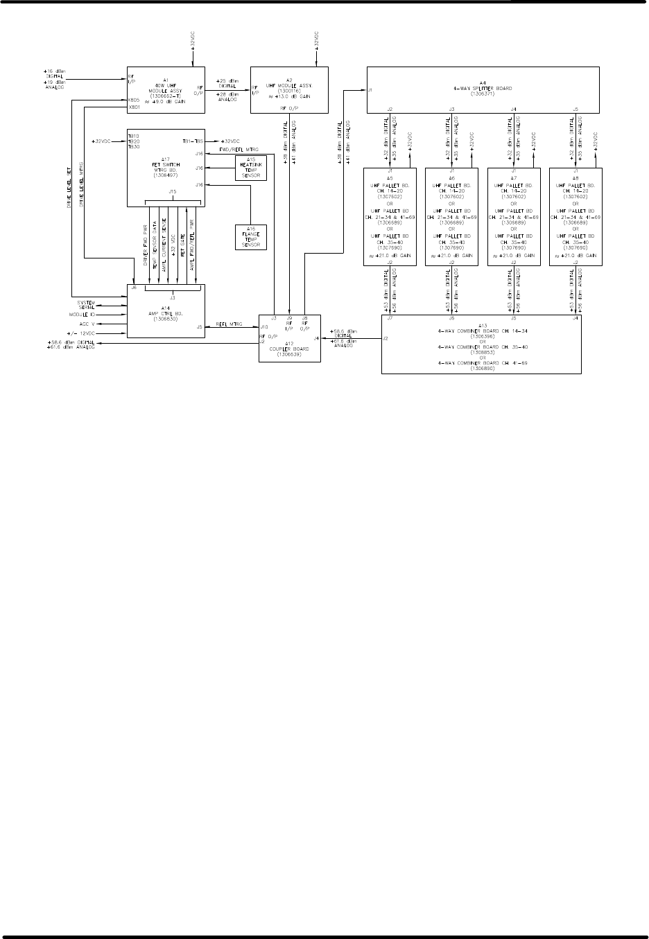
Innovator HX Series Digital Chapter 3, UHF Amplifier Assembly and
UHF Transmitter Cabinet Assemblies Circuit Descriptions
Volume 2, Rev. 0 3-4
Figure 3-4: Block Diagram of the UHF Amplifier
Amplifiers can be replaced during
transmitter operation. No new alignment
work is necessary. The frequency-
dependent operating parameters for the
complete frequency range are stored in
the controller and are automatically
enabled by the frequency setting of the
exciter. The RS 232 port is used for the
factory alignment of operating
parameters, e.g., calibration of RF and
drain current test values.
The operating voltage Uop of +32 volts is
distributed to the final amplifier modules
by a current bus underneath the
combiner. In addition to Uop for the
modules, the amplifier requires auxiliary
voltages of ±12 volts for the control
board. The operating voltage and
current consumption of the individual
modules are captured in the combiner
board and passed to the control board
where they are available for
interrogation by the control unit.
Furthermore, threshold values are
monitored in the control board and, if a
fault condition arises, the operating
voltage for predriver A1 and driver A2 is
disconnected by the action of field effect
transistor mounted on the A17 FET
Switch regulator board. The fault
indication is stored and passed to the
control unit.
The measured values of the temperature
sensors A15, mounted on driver front,
and A16, mounted on final rear, are
passed to the control board where they
are monitored and available for
interrogation by the control unit.
The control board possesses a number of
LEDs that indicate the status of the
amplifier. Two of these LEDs are visible
through the front panel. The green
Module OK LED indicates fault-free
operation. The Green Enable LED
indicates that the enable is applied to
that assembly. It will not be lit if the
Enable is removed. It will be lit Amber if
the Enable is applied but the amplifier is
not operating.
A fault condition is indicated by a Red
Module OK, either continuously
illuminated or flashing Red. The flashing
Red LED interprets as follows:
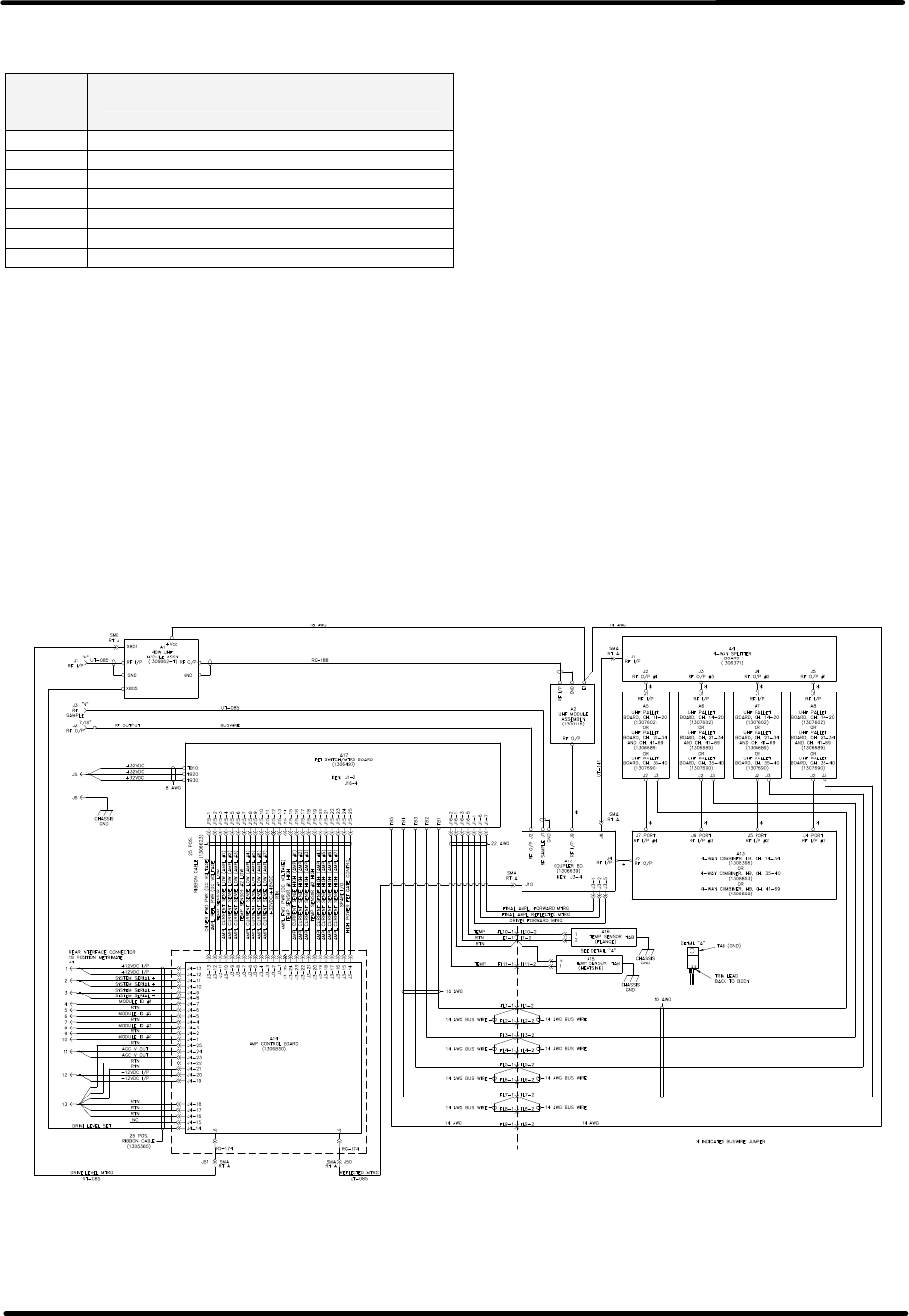
Innovator HX Series Digital Chapter 3, UHF Amplifier Assembly and
UHF Transmitter Cabinet Assemblies Circuit Descriptions
Volume 2, Rev. 0 3-5
Table 3-2: Module OK LED Red and
Blinking interpretation
Red
LED
Blinking Meaning
1 Blink Indicates Amplifier Current Fault
2 Blinks Indicate Temperature Fault
3 Blinks Indicate Power Supply Over Voltage Fault
4 Blinks Indicate Power Supply Under Voltage Fault
5 Blinks Indicate Reflected Power Fault
6 Blinks Indicate +12V or –12V Power Supply Fault
7 Blinks Indicate AGC Overdrive
3.2.1: Capture of Test Values in the
UHF Amplifier
The following test values are passed the
transmitter control unit:
• Forward power at the amplifier
output – rms output power
• Reflected power at the transmitter
output – peak level
• Operating voltage
• Current consumption of the modules
• Temperatures
The following test values are used only
for internal purposes on the control
board:
• Forward power behind drive module
A3 (not displayed in the control unit)
The following test points are available
for external equipment:
• RF test connector J3 on the front
panel
• Output power behind drive module
A3 (this test point is exclusively
intended for factory measurements)
Figure 3-5: Interconnect Typical UHF Amplifier Assembly

Innovator HX Series Digital Chapter 3, UHF Amplifier Assembly and
UHF Transmitter Cabinet Assemblies Circuit Descriptions
Volume 2, Rev. 0 3-6
3.2.2: Functional Description of the
Boards in the UHF Amplifier Tray
Assembly
3.2.2.1: (A1) 40 Watt UHF Module
Assembly (1306662; Appendix B)
The RF Input from the splitter assembly
(+18 dBm) is connected to the RF input
connection on (A1) the 40 Watt UHF
amplifier assembly, which has a gain of
approximately 9 dB. The assembly,
which operates class AB, is a highly
linear broadband amplifier for the
portion of the UHF band in which it is
operating. With a typical input of +18
dBm an output of +27 dBm is expected.
The output is set as needed to provide
the drive level to the UHF Module
Assembly that follows.
The amplification circuit consists of
LDMOS FET transistors V804 and V805
connected in parallel and operating in
class AB. The paralleling network is
achieved with the aid of 3 dB couplers
Z802 and Z803. A further 3 dB coupler
Z801, in conjunction with capacitors
C800 and C819, serves as a phase
shifter. Phase alignment, for the
complete amplifier, as well as quiescent
current settings are achieved by means
of potentiometers R807 and R808. The
settings are factory implemented and
should not be altered.
PIN diodes V810 & V811 form a variable
dampening circuit that is used to adjust
the amplification of the 40-watt module.
The adjustment is accomplished with the
Gain potentiometer R838. A
readjustment of the amplification may
be required, after repair work is
completed to ensure that the PAs in the
multiple PA transmitter delivers the
same output power.
3.2.2.2: (A2) UHF Module Assembly
(1300116; Appendix B)
The UHF Module Assembly, 250-watt
module is a broadband amplifier for the
portion of the UHF band in which it is
operating. The amplifier has
approximately 13 dB of gain. With a
typical input of +27 dBm an output of
+40 dBm is expected.
The amplification circuit consists of the
parallel-connected push-pull amplifier
blocks V1 and V2 operating in class AB.
In order to match the transistor
impedance to the characteristic
impedance of the input and output
sides, matching networks are placed
ahead and behind the amplifier blocks.
Transformers Z3 to Z6 serve to balance
the input and output signals. The
paralleling circuit is achieved with the
aid of 3-dB couplers Z1 and Z2.
The working point setting is factory
implemented by means of
potentiometers R9, R11, and R12 and
should not be altered.
3.2.2.3: (A12) Coupler Board
(1306639; Appendix B)
The UHF coupler board assembly provides
forward and reflected power samples of
the output to (A2) UHF module assembly
and also the output of the 4 way
combiner. The samples connect through
the FET Switch board to the amplifier
control board where it connects to the
input of the overdrive protection circuit.
The RF input to the UHF coupler
assembly, from the UHF module
assembly, 250 Watt, connects to jack J9.
The RF is connected by a strip line track
to the RF Output jack J8 that is cabled to
the 4 way splitter. A hybrid coupler
circuit picks off a power sample that is
connected to J3-5 as the forward driver
power sample.
Another RF input from the 4 way
combiner board, which is the RF output
for the tray, connects to jack J4. The RF
is connected by a strip line track to the
RF Output jack J2 that connects to the
front panel Jack J2, which is the RF
output for the UHF amplifier assembly.
Three hybrid coupler circuits pick off
power samples, two forward samples and
one reflected sample. One forward

Innovator HX Series Digital Chapter 3, UHF Amplifier Assembly and
UHF Transmitter Cabinet Assemblies Circuit Descriptions
Volume 2, Rev. 0 3-7
sample and the reflected sample connect
through the FET Switch board to the
amplifier control board. The other
forward sample connects to the RF
sample jack J3 located on the front panel
fro test purposes.
3.2.2.4: (A4) 4 Way Splitter Board
(1306371; Appendix B)
The (A4) 4-way splitter distributes the
output signal (+40 dBm) of the UHF
module assembly (A2) that was coupled
through the (A12) coupler board to the
splitter board, that connect to the four
parallel UHF Pallet Boards (A5 to A8).
The splitter circuit is in the form of micro
strips mounted on a Teflon board. The
actual splitter network does not
incorporate tuning elements. The
network provides for an equal splitting,
over the desired frequency range in the
UHF band, of the input at connector J1.
The input signal is first split in a ratio of
1:2. After this, both partial powers are
split in a second stage in the ratio of
1:2. The load (balancing) resistor of the
1:2 stage is formed by the series
connection of a 100Ω/10W power
resistor. The balancing resistors of both
1:2 stages are also in the form of
100Ω/10W resistors. Each output of the
splitter board is typically +34 dBm.
3.2.2.5: (A5-A8) UHF Dual Stage
Pallets (1307602, CH: 14-20 or
1306689, CH: 21-34 & 41-69, or
1307690,CH: 35-40; Appendix B)
The (A5, A6, A7 & A8) UHF Pallet Dual
Stage Amplifier Boards provide
approximately 21 dB of gain through
each of the boards. The RF input at a
level of approximately +34 dBm connects
to J1 on the board. The input is applied
to a hybrid splitter that produces two
outputs, one at 0° and one at -90°. Each
output connects to identical circuits. The
-90° signal is applied to a 9:1
transformer assembly that produces two
180° out of phase outputs. The two
outputs connect to Q1 a dual FET,
configured in a push pull arrangement,
with approximately 16 dB of gain. The
amplified outputs of the FETs connect to
a 1:9 Balun assembly that combines the
two 180° out of phase signals into a
single -90° output. The -90° output
connects to one input of a hybrid
combiner circuit.
The 0° signal is applied to a 9:1
transformer assembly that produces two
180° out of phase outputs. The two
outputs connect to Q2 a dual FET,
configured in a push pull arrangement,
with approximately 16 dB of gain. The
amplified outputs of the FETs connect to
a 1:9 Balun assembly that combines the
two 180° out of phase signals into a
single 0° output. The 0° output connects
to one input of a hybrid combiner circuit.
The 0° and the -90° signals are combined
by a hybrid combiner circuit and
connected to J2 the RF output jack on the
board (≈+55 dBm).
The +32 VDC, from the 4-way combiner,
connects to J3 on the board. The voltage
is applied through the resistors R3 and
R9 and the transformers to the drains of
Q1 and Q2. The +32 VDC is also
connected to the regulator U1 that
supplies the source voltages through the
transformers to Q1 and Q2. R5, R6 and
R7 are adjusted at the factory to set up
the drain current of the devices and
should not be readjusted.
3.2.2.6: (A13) 4 Way Combiner
Board (1306396, CH: 14-34, or
1308853, CH: 35-40, or 1306890,
CH: 41-69; Appendix B)
The (A13) 4-way combiner combines the
output signals of the UHF pallet
boards+55 dBm into a single output
typically +58.6 dBm, that connects
through the coupler board to the output
jack for the tray.
The combiner circuit is in the form of
Baluns mounted on a Teflon board. The
actual combiner network does not
incorporate tuning elements. The
network provides for equal combining,

Innovator HX Series Digital Chapter 3, UHF Amplifier Assembly and
UHF Transmitter Cabinet Assemblies Circuit Descriptions
Volume 2, Rev. 0 3-8
over the desired frequency range in the
UHF band, of the four inputs at
connectors J1-J4. The signals at J1 and
J2 are combined at a ratio of 2:1 and
the signals at J3 and J4 are combined at
a ratio of 2:1. After this, both combined
powers are combined again in a second
stage in the ratio of 2:1. The load
(balancing) resistors of all three 2:1
stages are 50Ω/250W power resistors, a
total of six. The combined RF output of
the board is at J5 and is typically +58.6
dBm 724 Watts in level.
3.2.2.7: (A17) FET Switch/Metering
Board (1306497; Appendix B)
The FET switch/metering board provides
protection of the +32 VDC to the
amplifier modules in the tray, feed
through connection of the forward and
reflected power samples and feed
through connections of the temperature
sensors A15 and A16 mounted on the
heatsink assembly.
The (A12) coupler board provides
voltages proportional to the forward and
reflected output power of the 4 way
combiner. These test voltages are
coupled through and passed to the
amplifier control board through J15-2 for
reflected power and J15-14 for forward
power. A sample of the (A2) UHF
module assembly forward power
connects through the FET
Switch/Metering Board at J15-1 that is
supplied as a driver sample to the
amplifier control board.
3.2.2.7.1: Operating Voltages for the
Amplifier Boards
The operating voltage of +32 volts is
distributed to each of the UHF pallet
amplifier boards, TB4 to A8, TB3 to A7,
TB2 to A6, and TB1 to A5. The +32
volts is also distributed to the A2 UHF
Module assembly and the (A1) 40 Watt
UHF Module Assembly through TB5.
The FET switch/metering board will
remove the +32 VDC from the amplifier
boards during hot replacement of the
UHF Amplifier Assembly. The FETs Q1,
Q2 and Q3 are controlled by the high
power gate control that is applied to
J15-25 from the Amplifier Control Board.
The drain currents of the power
transistors on the UHF pallet boards are
captured by .05? precision resistors
connected to their supply lines. The
voltage drops across these resistors are
passed to the amplifier control board
through 43.2k? bleeder resistors in
parallel. In addition, the operating
voltage is also passed to the control
board for monitoring purposes.
Critical operating parameters, including
current high or low and temperature, of
the amplifiers are monitored on the
amplifier control board through the FET
board. If threshold values are exceeded,
the amplifier control board switches off
the operating voltages for the predriver,
driver and final amplifiers through the
FETs Q1, Q2 and Q3 on the FET
switch/metering board.
3.2.2.8: (A14) Amplifier Control Board
(1308540 or 1306830; Appendix B)
All protective, switching, display, and
monitoring functions required for the
operation of the UHF amplifier assembly
are realized by the amplifier control
board. The control board is mounted in
a RF enclosure behind the front panel of
the amplifier and performs the following
tasks:
• Capture and processing of test
values
• Fault protection for the amplifier
modules
• Generating the actual value for
transmitter ALC
• Communication with the transmitter
control unit
The circuits in the control board do not
contain elements that can be adjusted.
All of the required settings are software
implemented in the factory through an
RS 232 port and must not be altered.
Innovator HX Series Digital Chapter 3, UHF Amplifier Assembly and
UHF Transmitter Cabinet Assemblies Circuit Descriptions
Volume 2, Rev. 0 3-9
3.2.2.8.1: Schematic Page 1
Upper center of page one is U2, which is
the microcontroller. This in-circuit Atmel
microcontroller is operated at 3.6864
MHz. Programming of this device is
performed through J2. PF4 and PF5 are
analog inputs for ICs U33 and U34 on
page 4. The desired analog channels of
U33 and U34 are selected by the setting
of PA0, PA1, & PA2. PA3 of U2 drives a
processor operating LED that can be
flashed to show continued operation.
PF0 and PF1 are used to monitor the
+12V and -12V supplies to the board.
PF3 is connected to a via for future
access. PB3,4,5,6 and 7 are used to
indicate different hardware revisions to
the operating software.
U6 is our standard serial to RS-485
driver IC. Resistor R25 sets U6 to
transmit mode when the micro is held in
reset or PE2 is configured as an input.
U4 is a watchdog IC used to hold the
microcontroller in reset if the supply
voltage is less than 4.21 VDC; (1.25
VDC < Pin 4 (IN) < Pin 2 (Vcc)). U4
momentarily resets the microcontroller if
Pin 6 is not clocked every second.
U3 is a RS-232 serial port on UART 1 of
the micro controller. J1 is used to
provide front panel RS-232 access
(without hardware handshaking). A
standard NULL modem cable is needed
to connect to a PC. For test and debug,
all data into and out of the RS-485
interface of UART0 is transmitted out
through a pin of J1 (this pin is usually
not used unless hardware handshaking
is implemented).
U1, located in the Upper left corner, is
used to determine where the amplifier
control board is located. Module ID 1, 2
and 3 inputs require an external pull-
down to ground to set the logic state but
Module ID 4 requires an external pull-
up. Diodes such as CR1 prevent un-
powered modules from pulling down the
Module ID lines of other installed
modules. The external pull-down to
ground connections are made in the
amplifier cabinet wiring harness.
U36 below U1 is used to reset faults that
are detected on pages 2 and 5. Circuits
of page 2 and 5 hold a fault condition so
that the microcontroller has enough time
to detect the fault and operate
accordingly.
U5 is below U36 and is used to control
the board's status LEDs, DS3 Amplifier
Enabled and DS4 Module OK (See Table
3-3), and other circuits that are not
allowed to change state during a
microcontroller reset. The LEDs are
controlled by a FET that is turned on to
shut current away from the LED to turn
it off.
U7 is located below U5. U7 is used
transfer the latched fault conditions into
the microcontroller U2.
Table 3-3: Module OK LED Red and
Blinking interpretation
Red
LED
Blinking Meaning
1 Blink Indicates Amplifier Current Fault
2 Blinks Indicate Temperature Fault
3 Blinks Indicate Power Supply Over Voltage Fault
4 Blinks Indicate Power Supply Under Voltage Fault
5 Blinks Indicate Reflected Power Fault
6 Blinks Indicate +12V or –12V Power Supply Fault
7 Blinks Indicate AGC Overdrive Fault
3.2.2.8.2: Schematic Page 2
In the upper center section of page 2 are
circuits with U35, U11 and U12. When
the cabinet high power supply is
enabled, U35A generates a regulated
voltage that is about 7.5 Volts less than
the +32 / +48 Volt high power supply.
U11 and U12 generate a regulated
voltage that is about 10 Volts more than
the high power supply. This voltage is
regulated to produce a signal that is
about 4.4 VDC above the high voltage
supply. The PS +4.4VDC regulated
power is used to power the unity gain
op-amp circuits located on page 3.
The PS +10VDC output is also used to
drive the gate of two external power

Innovator HX Series Digital Chapter 3, UHF Amplifier Assembly and
UHF Transmitter Cabinet Assemblies Circuit Descriptions
Volume 2, Rev. 0 3-10
FETs. These FETs are located within the
amplifier module and are used to control
the high power supply current to the
amplifier pallets. Since the high power
supply can be +48 Volts and the
2N7002LT1 is rated for a maximum
Drain to Source voltage of 60 Volts, Q9
along with Q8 make a circuit that
controls the high power supply control
voltage of the two external power FETs.
Q13 allows the hardware to
automatically disable the external power
FETs on detection of a critical fault. Q19
quickly reduces the drive level when a
fault is detected.
U50 detects the high power supply
voltage. U51 indicates that the power
supply voltage is too low. U58 is a
digital potentiometer that sets the over
voltage and under voltage fault
thresholds. U37 latches the fault so that
the microcontroller can observe the fault
condition even after the cause of the
fault is removed.
3.2.2.8.3: Schematic Page 3
Current Monitoring Circuits:
A 0.01 ohm resistor is used within the
amplifier module for monitoring the
current through several sections of the
amplifier. The voltage developed across
this resistor is provided to the control
board through current limiting resistors.
The control board also has current
limiting resistors and filtering capacitors
on the input circuits. Due to the input
bias current of the Linear Technology
LT1787HVCS8 precision high side
current sense amplifiers, the current
sense amplifiers can not be directly
connected to the resistive components.
A unity gain low input offset op-amp is
used in both the high and low side sense
lines. Voltage supplied to these parts
must be above the high voltage supply
rail and the V- pin must be less than the
high voltage supply but not as for down
as ground. The 43.2 Kohm resistor from
Pin 5 to ground sets the gain of the
current sense amplifiers to about 17.28.
This value is not set with much accuracy
since the manufacture internally
matches the resistors of this part but
their actual resistance value is not
closely defined. A digital potentiometer
is connected to each of the high current
monitoring circuits to allow for
calibration of the measured current prior
to the over current detection circuits.
3.2.2.8.4: Schematic Page 4
The upper left corner contains U33 and
U34. These are the analog multiplexer
IC that are used to route select analog
signals into the microcontroller.
U32B converts the detected forward
power level into a module AGC output
voltage. CR51 allows the module's AGC
output voltage to be connected to other
module AGC voltages. If this module
has the highest detected forward power
in a multi-amplifier system, it will have
the highest forward power signal. This
signal level into U32B pin 5 will be used
to set the AGC output voltage of the
system. If another amplifier has a
higher forward power, the level into
U32B pin 6 will be higher than pin 5 and
this amplifiers output signal will not be
used to set the AGC voltage level.
High speed comparators U52, 53, 54,
and 55 monitor the current of the RF
amplifier pallets. If any level is greater
than the fault level set by the digital
potentiometer U43, the fault is detected
and held by U41.
Other digital potentiometers on this
page set the reflected power fault
threshold, over drive fault threshold and
the drive level.
3.2.2.8.5: Schematic Page 5
The modules reflected power and driver
input forward power are monitored
through RF detection circuits of the
control board on this schematic page. If
the reflected power is greater than the
fault threshold set by U43 pin 5, located
on page 4, U56 will indicate a reflected
power fault. If the drivers input power
is greater than the fault threshold set by
Innovator HX Series Digital Chapter 3, UHF Amplifier Assembly and
UHF Transmitter Cabinet Assemblies Circuit Descriptions
Volume 2, Rev. 0 3-11
U44 pin 13, located on page 4, U57 will
indicate an over drive fault. These faults
are latched for detection by the
microcontroller and they are also used
by CR66 and CR67, located on page 2,
to immediately remove the supply
voltage of the main control FETs.
The RF forward power detection circuits
are calibrated on the combiner board
and the DC output voltages of these
circuits are passed to the control board
over the ribbon cable connection
between the boards.
In the lower right corner of the page are
voltage regulator circuits. U29 is rated
for 0.14 amps of power using its 92 C/W
rating if Ta = 60C max and Tj = 125C
max. 0.26 amps can be obtained from
U29 if the mounting pad is 0.5 square
inches. The controller does not typically
need this much current. U30 and U31
are low drop-out voltage regulators with
a tolerance greater than or equal to 1%.
100 mA is available from each of the
devices.
3.3: Troubleshooting and Repair of
the Amplifier
3.3.1: Safety Information
Work on the amplifier must only be
carried out by qualified personnel
according to good electrical engineering
practice, taking into account all relevant
safety precautions. Furthermore, the
following should be noted:
• Before working on an amplifier, e.g.,
removing cables, removing the front
panel etc., ensure that the amplifier
is disconnected from the operating
voltages. Carry out all work with
extreme caution.
3.3.2: Troubleshooting
3.3.2.1: Front Panel LEDs
A visual indication of the operating
status of the UHF amplifiers is signaled
by front panel LEDs. Fault-free
operation is signaled by the lit Green
Module OK LED, located nearest the
handle. A fault condition is indicated by
a Module OK, either continuously
illuminated Red or flashing Red.
The flashing Red Module OK LED
interprets as follows:
Table 3-4: Module OK LED Red and
Blinking interpretation
Red
LED
Blinking Meaning
1 Blink Indicates Amplifier Current Fault
2 Blinks Indicate Temperature Fault
3 Blinks Indicate Power Supply Over Voltage Fault
4 Blinks Indicate Power Supply Under Voltage Fault
5 Blinks Indicate Reflected Power Fault
6 Blinks Indicate +12V or –12V Power Supply Fault
7 Blinks Indicate AGC Overdrive
The other LED is the Enable LED, located
nearest the edge. It is Green when an
Enable is applied to that amplifier and it
is operating. It will not be lit if the
Enable is removed. It will be lit Amber if
the Enable is applied but the amplifier is
not operating.
3.3.2.2: Polling Fault Indications
Detected fault conditions are passed to
the control unit. The fault indications are
entered in a list and can be viewed at
any time during transmitter operation.
The system control unit is used for
polling stored fault indications and
reading actual operating parameters.
3.4: Exchanging Amplifiers
For reasons of safety, amplifier modules
MUST be in standby (RF disabled)
before any connections are removed. If
the amplifier control board is loaded
with software version 2.4 or high, an
Axcera Amplifier disable plug (1308219)
can be used to place an individual
module in standby. Regardless of the
version of code, any power amplifier
may safely be removed by disabling its
power supply. The power supply, either
the top power supply #1 for the top four
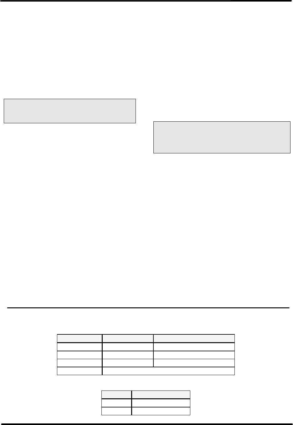
Innovator HX Series Digital Chapter 3, UHF Amplifier Assembly and
UHF Transmitter Cabinet Assemblies Circuit Descriptions
Volume 2, Rev. 0 3-12
Amplifier assemblies, or the bottom
power supply #2 for the bottom four
Amplifier assemblies, may be isolated
from main AC power by switching off the
appropriate front panel circuit breaker.
This is accomplished by tripping the
respective breaker located on the circuit
breaker assembly panel, at the bottom
of the amplifier cabinet.
3.4.1: Exchange of a Module
Caution: The load (balancing)
resistors in the modules contain
Beryllium Oxide.
Remove the amplifier from the cabinet
as described in the Chapter 2 section
2.5.3 of this volume.
Undo the side panel of the amplifier.
Unsolder the connections for the
operating voltage as well as the RF input
and output connections of the defective
module.
NOTE: The temperature sensors A15 or
A16 may need to be unscrewed to
remove the module.
After undoing the screws, the module
can be lifted from the heat sink.
Remove the old heat-transfer paste from
the heat sink.
NOTE: In order to ensure proper heat
conduction, the contact surface of the
heat sink must be clean and free of
foreign particles.
3.4.2: Mounting a New Module
Apply a thin film of heat-transfer paste
to the contact surface.
Fix the module into position with the
mounting screws. At first, only tighten
the screws by hand.
Next, tighten the screws, in repeated
steps, to a torque of 0.8 Nm (7 in/lb).
Caution: A torque of 1.2 Nm
(10 in/lb) must not be exceeded.
(1.2 NM ˜ 10 in/lb)
(0.8 Nm ˜ 7 in/lb)
3.4.3: Final Steps
Replace the cover on the amplifier,
insert the module into the transmitter
cabinet, and make the RF input and
output connections as described in
Chapter 2 section 2.5.3 of this volume.
NOTE: Alignment work on the amplifier
is not required. They are set at the
factory for both phase and gain control
and provide less than 0.5 dB difference
between the amplifiers. The exchange
of a module should be reported to
Axcera with information on the cause of
the fault, module location, identification
number of the amplifier, and the type of
transmitter.
3.4.4: External Connections to Amplifier Assembly
Table 3-5: RF Connectors on the Front Panel
Connector Assignment Type
J1 RF Input Female N-type
J2 RF Output Female HF 7/16”
J3 RF Test Point Female N-type
RS 232 C reserved for factory alignment only!
Table 3-6: Operating Voltage Connection (Rear Panel)
Pin Assignment
J5 +32 V
J6 Ground
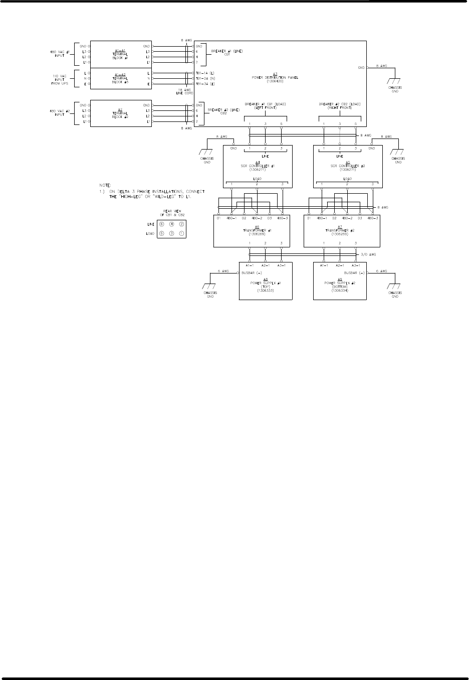
Innovator HX Series Digital Chapter 3, UHF Amplifier Assembly and
UHF Transmitter Cabinet Assemblies Circuit Descriptions
Volume 2, Rev. 0 3-13
3.5: Power Supply Assembly
Figure 3-6: AC Wiring Harness UHF Amplifier Cabinet
3.5.1: +32 VDC Power Supplies
Overview
The DC voltages to the UHF amplifier
assemblies mounted in each UHF
amplifier cabinet are supplied by either
one or two linear power supply
assemblies. One supply, titled the top
power supply #1, provides +32 VDC to
the four UHF amplifier assemblies
mounted at the top of the cabinet for 5
kW amplifier cabinets or three UHF
amplifier assemblies mounted at the top
of the cabinet for 3.7 kW amplifier
cabinets. The other supply, titled the
bottom power supply #2, provides +32
VDC to the four UHF amplifier
assemblies mounted at the bottom of
the cabinet for 2.5 & 5 kW amplifier
cabinets or to three UHF amplifier
assemblies mounted at the bottom of
the cabinet for 1.8 or 3.7 kW amplifier
cabinets.
(Refer to Figure 3-6) Two input AC
connections of 480 VAC, 3 phase or 208
VAC 3 phase and one 110 VAC input
connection are needed to operate each
UHF Amplifier Cabinet. The 110 VAC
input connects to the (A1-A2) Terminal
Block #3 mounted at the top left side, at
the rear of the cabinet. The 110 VAC is
wired directly to a terminal block TB1
located in the AC power distribution
panel mounted at the bottom of the
cabinet. One of the 480/208 VAC, 3
phase inputs connects to the (A1-A1)
Terminal Block #1 and the other to the
(A2) Terminal Block #2 mounted top left
side, at the rear of the cabinet. The two
480/208 VAC inputs are wired directly to
each of the circuit breakers located in
the AC power distribution panel mounted
at the bottom of the cabinet. The AC
input voltages to the two power supplies
are controlled through the two 480 VAC
30 Amp or 208 VAC 50 Amp 3 Phase
circuit breakers located on the (A3) AC
power distribution panel. The left front
circuit breaker controls the voltage to
power supply #1 and the right front
circuit breaker controls the voltage to
power supply #2.
The two +32 VDC power supplies, (A8)
#1 and (A9) #2, are identical with each
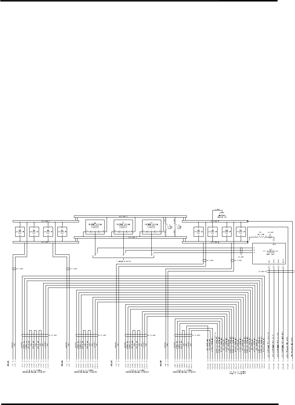
Innovator HX Series Digital Chapter 3, UHF Amplifier Assembly and
UHF Transmitter Cabinet Assemblies Circuit Descriptions
Volume 2, Rev. 0 3-14
containing a SCR Controller, a
transformer and a linear power supply.
3.5.2: SCR Controllers
The two SCR controllers, (A4) SCR
Controller #1 and (A5) SCR Controller
#2, Model #3629C, are manufactured by
Control Concepts, Inc. The SCR
controller is of a phase angle, pulse
width, control design. The output power
is regulated by varying the point at
which the SCR is turned on within each
half cycle. NOTE: More detailed
information is supplied in the
manufacturer instruction manual that is
supplied with the SCR Controller.
3.5.3: Step Down Transformers
The outputs of the two SCR controllers
connect to one of the two three phase
480/208 VAC step down transformers.
The (A6) Transformer #1 or (A7)
Transformer #2, whose input
connections are set at the factory
depending on the input voltage provided
and supplies three outputs that connect
directly to the input of the linear power
supply assemblies.
3.5.4: Linear Power Supply
Assemblies (1306333 Top, 1306334
Bottom; Appendix C)
(Refer to Figures 3-7 & 3-8) Both of the
Power Supply Assemblies, Top #1 and
Bottom #2, are identical, electrically, in
operation, the only differences are in the
physical assembly itself.
The three stepped down outputs of the
transformer, approximately 100 VAC,
connect to one of the three Rectifier
Modules. The rectifier modules are full
wave rectifiers that each produce
+32 VDC that are summed in parallel at
the Bus Bars A and B. The +32 VDC
outputs are filtered by the eight A4-A11
220,000µF capacitors. Capacitors A4-A7
through Bus Bar C are for Amps #1 and
#2 and capacitors A8-A11 through Bus
Bar E are for Amps #3 and 4.
Figure 3-7: Linear Power Supply #1, Top
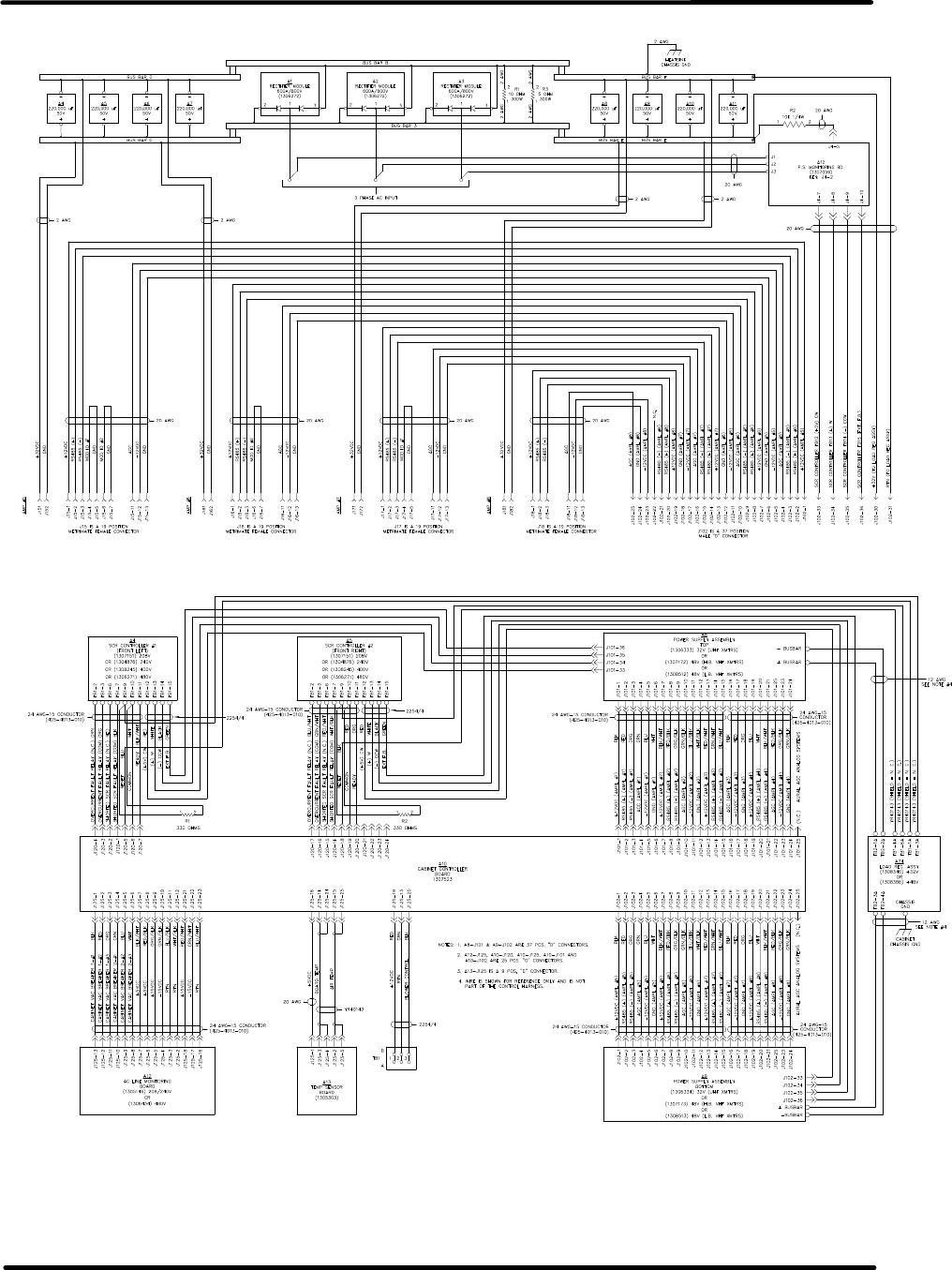
Innovator HX Series Digital Chapter 3, UHF Amplifier Assembly and
UHF Transmitter Cabinet Assemblies Circuit Descriptions
Volume 2, Rev. 0 3-15
Figure 3-8: Linear Power Supply #2, Bottom
Figure 3-9: Control Interconnect Cabinet Full Controller System

Innovator HX Series Digital Chapter 3, UHF Amplifier Assembly and
UHF Transmitter Cabinet Assemblies Circuit Descriptions
Volume 2, Rev. 0 3-16
3.6: Full Amplifier Cabinet Controller
Board (1307523; Appendix A)
Your amplifier cabinet will contain the
full amplifier cabinet controller assembly
or the half amplifier cabinet controller
assembly. The half amplifier cabinet
controller assembly is described in the
next section.
The full amplifier cabinet controller
board is mounted in the Full Amplifier
Cabinet Controller Assembly (1305453).
The assembly is located facing the back
of the cabinet mounted on the rear of
the top combiner assembly and controls
the entire amplifier cabinet.
3.6.1: Page 1 of the Schematic Drawing
(1307524; Appendix A):
Centered in page one is the
microcontroller (U6). This in-circuit
programmable Atmel microcontroller is
operated at 3.6864 MHz. Programming
of this device is performed through
J105. PF2 is an analog input that
connects to a multiplexer U9 and PF3 is
another analog input that connects to
the multiplexer U5. The desired
multiplexer analog channels are selected
by the setting of PA0, PA1, & PA2. PF0
and PF1 are used to monitor the +12V
and -12V supplies to the board.
(U12) is a watchdog IC that is used to
hold the microcontroller in reset if the
supply voltage is less than 4.21 VDC;
(1.25 VDC < Pin 4 (IN) < Pin 2 (Vcc)).
U12 will momentarily reset the
microcontroller if Pin 6 is not clocked
every second.
The (U6) Microcontroller UART 0 is used
to communicate with each of the
amplifier modules, Cabinet Serial. U10
is a RS-485 transceiver IC for cabinet
serial communication to the amplifier
modules.
The (U6) Microcontroller UART 1 is used
to communicate with the transmitter's
exciter or exciter switcher, System
Serial. U8 is a RS-485 transceiver IC.
The IC U2, Serial Address, located in the
Upper left corner, is used to determine
where the amplifier control board is
located. Rotary switch SW1 determines
the cabinet number and thus the
cabinet's serial address. The upper
three bits of U2 can be used to
determine physical board characteristics.
Bit 6 will be reserved for a half cabinet
controller to determine if the controller
is the top half controller or the bottom
half controller.
The IC U3, SCR Controllers, below U2, is
used to monitor the status of the SCR
controllers. U7 below U3 is connected to
an 8 position DIP switch, SW2, which
can be used to enable select firmware
options. See Table 3-7.
U11, below U7, is used to control the
SRC controller, the cabinet's cooling
blower FET, and the Processor Operating
LED, DS2. The use of this IC allows
these circuits to remain stable during a
microcontroller reset.
3.6.2: Page 2 of the Schematic Drawing
(1307524; Appendix A):
In the upper left section of Page 2 are
circuits that interface with the exhaust
air temperature board and the low
power +15VDC switching supply.
Control of an external cooling blower
relay is available through J125 pin 20.
When the cabinet's RF output is enabled,
the external blower relay is energized by
the enabling of Q3 on page 1.
Voltage samples of the cabinet's high
power AC inputs are monitored through
inputs of J125.
On the upper right side of the schematic,
the Power Supply SCR Controller
interface section routes signals need to
control the high power supply. R120,
R121, R122, and R123 are used to set
the output voltage of the high power
supply.
Amplifier module interfaces are routed
through J101, for modules 1-4, and

Innovator HX Series Digital Chapter 3, UHF Amplifier Assembly and
UHF Transmitter Cabinet Assemblies Circuit Descriptions
Volume 2, Rev. 0 3-17
J102, for modules 5-8. Each amplifier
module has independent RS-485
transceivers and power sources that are
current limited with self-resetting fuses.
The RS485 interface section, located in
the lower right section of the schematic,
defines the RS-485 loop through
connections that also contain the
system's AGC signals. Circuitry in the
lower portion of this block is used to
convert cabinet AGC voltages into
system AGC voltages. If the cabinet
level voltages are greater than the
system levels, U13 increases its output
to drive the system level to match the
cabinet level. Cabinet AGC levels are
set by the highest AGC voltage of the
install amplifier modules.
3.6.3: Page 3 of the Schematic Drawing
(1307524; Appendix A):
In the upper left portion of the
schematic, R125 is used to measure the
cabinet's inlet air temperature. Also
defined on this page are the board's
voltage regulators. The cabinet's +15V
supply is used by U14 and U17 to
generate +12V for all of the amplifier
modules. The cabinet's -15V supply is
used by U19 to generate -12V for all of
the amplifier modules. The +12V signal
is further regulated by U16 to +7 VDC
then regulated again to separate digital
+5V by U18 and analog +5V by U15.
The digital +5V regulator U18 is not as
precise as the analog +5V regulator U15
but it is capable of high current loads.
3.6.4: Page 4 of the Schematic Drawing
(1307524; Appendix A):
These circuits take the forward and
reflected RF power samples and converts
the signals to DC values used to provide
power levels for the cabinet monitoring.
The RF detection circuits are made up of
diodes and separate op-amps. Once the
detected voltages are amplified, the
signals are fed through power calibration
potentiometers, R110, R11, R112, R113
or R114, before they are fed through
unity gain amplifiers, U20, U23A, U23B,
U24A or U24B to the microcontroller's
multiplexer.
3.6.5: Page 5 of the Schematic Drawing
(1307524; Appendix A):
These eight circuits are individual RS-
485 transceiver ICs for serial
communication with the amplifier
modules. The RS-485 transceiver ICs
contain components that maintain the
receive channel in a high output state
when the inputs are left open, shorted
together or terminated with no signal.
The transmit and receive channels of
each transceiver are individually
controlled by the microcontroller.
During reset or programming of the
microcontroller, pull-up and pull-down
resistors are used to place the
transceivers in a tri-state condition.
Each amplifier RS-485 connection is
terminated with a 120 ohm resistor.
Table 3-7: Firmware Configuration of SW2 on Full Amplifier Cabinet Controller Board
Switch
Number Function Position Normal
Operating
Position
SW2-1 Reserved for Factory Test 0 = Off
1 = On Off - Must
be Off
SW2-2 Allow Power Supply Enable on
Cooling FLT 0 = Off
1 = Allow Off - Must
be Off
SW2-3 Allow Power Supply Enable on
RFL PWR FLT 0 = Off
1 = Allow Off
SW2-4 High Voltage Supply Range 0 = 220
1 = 440 System
dependent
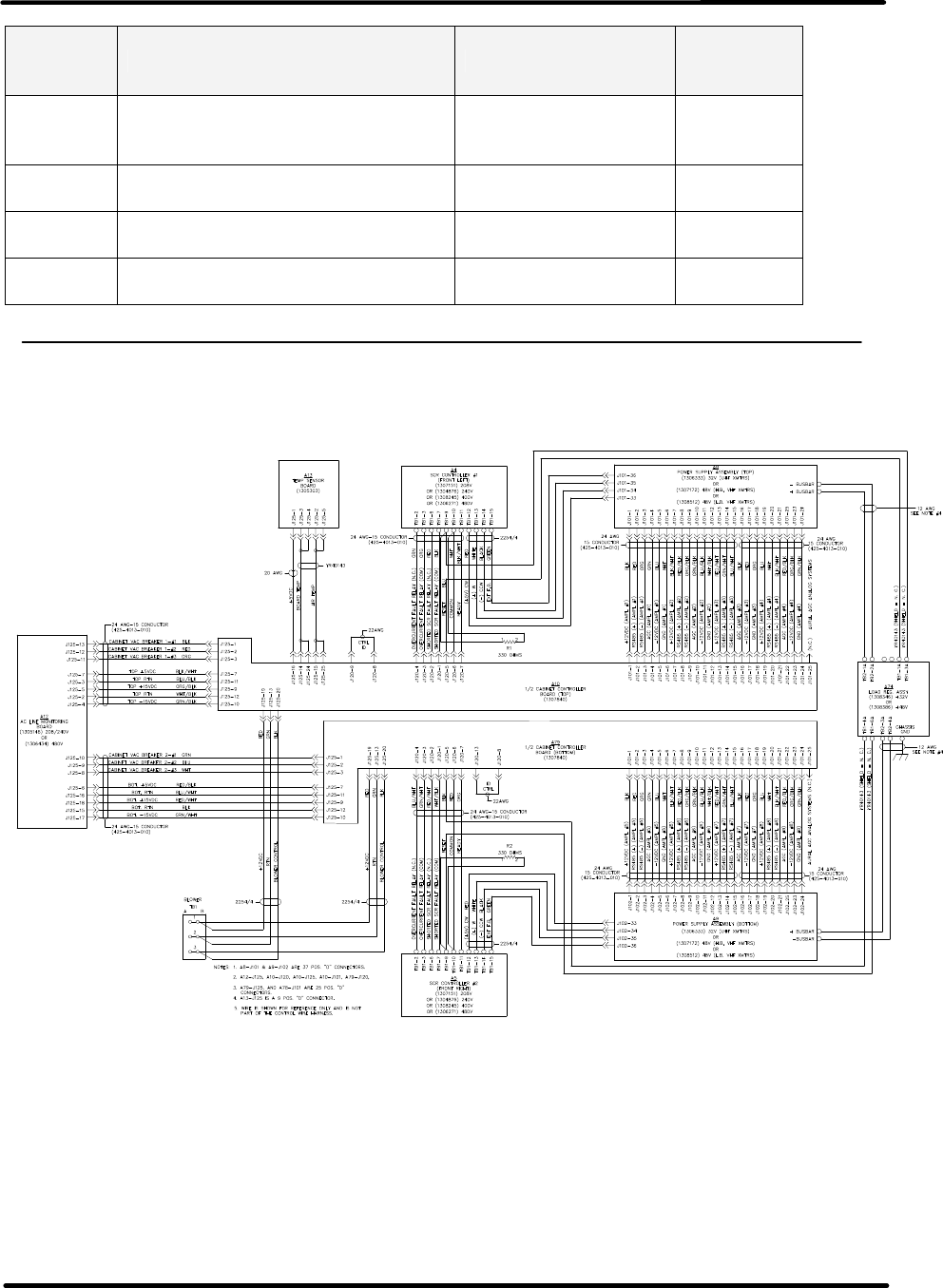
Innovator HX Series Digital Chapter 3, UHF Amplifier Assembly and
UHF Transmitter Cabinet Assemblies Circuit Descriptions
Volume 2, Rev. 0 3-18
Switch
Number Function Position Normal
Operating
Position
SW2-5 Reflected Power RF Source 0 = J112
1 = J114 (If not
Externally Diplexed)
System
dependent
SW2-6 Allow Power Supply Enable on
Reject Load Faults 0 = Off
1 = Allow Off
SW2-7 Reserved for Factory Test 0 = Off
1 = On Off - Must
be Off
SW2-8 Reserved for Factory Test 0 = Off
1 = On Off - Must
be Off
NOTE: These switch positions are factory set and should not be changed.
Figure 3-10: Control Interconnect Cabinet Half Controller System

Innovator HX Series Digital Chapter 3, UHF Amplifier Assembly and
UHF Transmitter Cabinet Assemblies Circuit Descriptions
Volume 2, Rev. 0 3-19
3.7: Half Amplifier Cabinet Controller
Board (1307840; Appendix A)
The half amplifier cabinet controller
board is mounted in the Half Amplifier
Cabinet Controller Assembly (1307847).
There are typically two assemblies,
which are mounted facing the rear of the
cabinet. One controller is mounted on
the rear of the top combiner assembly,
which controls the top power supply and
amplifier module assemblies and one
mounted on the rear of the bottom
combiner assembly which controls the
bottom power supply and amplifier
module assemblies.
3.7.1: Page 1 of the Schematic Drawing
(1307841; Appendix A):
Centered in page one is the
microcontroller (U6). This in-circuit
programmable Atmel microcontroller is
operated at 3.6864 MHz. Programming
of this device is performed through
J105. PF2 is an analog input that
connects to a multiplexer U9. PF3 is
another analog input that connects to
the multiplexer U5. The desired
multiplexer analog channels are selected
by the setting of PA0, PA1, & PA2. PF0
and PF1 are used to monitor the +12V
and -12V supplies to the board.
(U12) is a watchdog IC that is used to
hold the microcontroller in reset if the
supply voltage is less than 4.21 VDC;
(1.25 VDC < Pin 4 (IN) < Pin 2 (Vcc)).
U12 will momentarily reset the
microcontroller if Pin 6 is not clocked
every second.
The Microcontroller UART 0 is used to
communicate with each of the amplifier
modules, Cabinet Serial. U10 is a RS-
485 transceiver IC for cabinet serial
communication to the amplifier modules.
The Microcontroller UART 1 is used to
communicate with the transmitter's
exciter or exciter switcher, System
Serial. U8 is a RS-485 transceiver IC.
The IC U2, Serial Address, located in the
Upper left corner, is used to determine
where the amplifier control board is
located. Rotary switch SW1 determines
the cabinet number and thus the
cabinet's serial address. The upper
three bits of U2 can be used to
determine physical board characteristics.
The IC U3, SCR Controllers, is located
below U2. U3 is used to monitor the
status of the SCR controllers. U7 below
U3 is connected to an 8 position DIP
switch, SW2, which can be used to
enable select firmware options. See
Table 3-7.
U11, below U7, is used to control the
SRC controller, the cabinet's cooling
blower FET, and the Processor Operating
LED, DS2. The use of this IC allows
these circuits to remain stable during a
microcontroller reset.
3.7.2: Page 2 of the Schematic Drawing
(1307841; Appendix A):
In the upper left section of Page 2 are
circuits that interface with the exhaust
air temperature board and the low
power +15VDC switching supply.
Control of an external cooling blower
relay is available through J125 pin 20.
When the cabinet's RF output is enabled,
the external blower relay is energized by
the enabling of Q3 on page 1.
Voltage samples of the cabinet's high
power AC inputs are also monitored
through inputs of J125.
Power Supply SCR Controller interfaces
are documented in the upper right side
of the schematic. This section routes
signals need to control and monitor one
of the high power supply SCR
controllers. Supply voltage and reject
load monitoring signals are also routed
through J120.
The four amplifier module interfaces are
routed through J101. Each amplifier
module has independent RS-485
transceivers and power sources, that are
current limited with self-resetting fuses.

Innovator HX Series Digital Chapter 3, UHF Amplifier Assembly and
UHF Transmitter Cabinet Assemblies Circuit Descriptions
Volume 2, Rev. 0 3-20
The RS485 interface section, located in
the lower right section of the schematic,
defines the RS-485 loop through
connections and contains the system's
AGC signals. Circuitry in the lower
portion of this block is used to convert
cabinet AGC voltages into system AGC
voltages. If the cabinet level voltages
are greater than the system levels, U13
increases its output to drive the system
level to match the cabinet level. Cabinet
AGC levels are set by the highest AGC
voltage of the installed amplifier
modules.
3.7.3: Page 3 of the Schematic Drawing
(1307841; Appendix A):
In the upper left portion of the
schematic, R125 is used to measure the
cabinet's inlet air temperature. Also
defined on this page are the board's
voltage regulators. The cabinet's +15V
supply is used by U14 to generate +12V
for all of the amplifier modules. The
cabinet's -15V supply is used by U19 to
generate -12V for all of the amplifier
modules. The +12V signal is further
regulated by U16 to +7 VDC then
regulated again to separate digital +5V
by U18 and analog +5V by U15. The
digital +5V regulator U18 is not as
precise as the analog +5V regulator U15
but it is capable of high current loads.
3.7.4: Page 4 of the Schematic Drawing
(1307841; Appendix A):
These circuits take the forward and
reflected RF power samples and converts
the signals to DC values used to provide
power levels for the cabinet monitoring.
The RF detection circuits are made up of
diodes and separate op-amps. Once the
detected voltages are amplified, the
signals are fed through power calibration
potentiometers, R110, R11, R112, R113
or R114, before they are fed through
unity gain amplifiers, U20, U23A, U23B,
U24A or U24B to the microcontroller's
multiplexer.
3.7.5: Page 5 of the Schematic Drawing
(1307841; Appendix A):
These four circuits are individual RS-485
transceiver Ics for serial communication
with the amplifier modules. The RS-485
transceiver ICs contain components that
maintain the receive channel in a high
output state when the inputs are left
open, shorted together or terminated
with no signal. The transmit and receive
channels of each transceiver are
individually controlled by the
microcontroller. During reset or
programming of the microcontroller,
pull-up and pull-down resistors are used
to place the transceivers in a tri-state
condition. Each amplifier RS-485
connection is terminated with a 120?
resistor.
Innovator HX Series Digital Chapter 3, UHF Amplifier Assembly and
UHF Transmitter Cabinet Assemblies Circuit Descriptions
Volume 2, Rev. 0 3-21
Table 3-8: Firmware Configuration of SW2 on Half Amplifier Cabinet Controller Board
Switch
Number Function Position Normal
Operating
Position
SW2-1 Reserved for Factory Test 0 = Off
1 = On Off - Must
be Off
SW2-2 Allow Power Supply Enable on
Cooling FLT 0 = Off
1 = Allow Off - Must
be Off
SW2-3 Allow Power Supply Enable on
RFL PWR FLT 0 = Off
1 = Allow Off
SW2-4 High Voltage Supply Range 0 = 220
1 = 440 System
dependent
SW2-5 Reflected Power RF Source 0 = J112
1 = J114 (If not
Externally Diplexed) System
dependent
SW2-6 Allow Power Supply Enable on
Reject Load Faults 0 = Off
1 = Allow Off
SW2-7 Reserved for Factory Test 0 = Off
1 = On Off - Must
be Off
SW2-8 Reserved for Factory Test 0 = Off
1 = On Off - Must
be Off
NOTE: These switch positions are factory set and should not be changed.
3.8: Temperature Sensor Board
(1309460; Appendix A)
The temperature sensor board is
mounted at the top of the amplifier
cabinet in the airflow path inside the
exhaust plenum. The board monitors
the temperature of the exhausted air
and reports it to the cabinet controller
board.
3.9: Reflected Metering Board
(1306988; Appendix A)
The reflected metering board is part of
the metering module assembly mounted
on the rear middle, left side of the
amplifier cabinet. The board monitors
the reflected power samples of up to
four circulators of the output combiner
assembly. Two reflected metering
boards are needed when two output
combiners are in the amplifier cabinet.
The board sends the reject levels to the
cabinet controller board.
3.10: Serial Loop-Thru Board
(1307811; Appendix A)
The serial loop-thru board is mounted on
the metering module assembly located
on the rear middle, left side of the
amplifier cabinet.
The function of the serial loop-thru board
is to provide an extra serial loop-thru that
connects to the second amplifier cabinet.
This prevents the system controller from
not recognizing any amplifier cabinets if
one system controller is removed.
NOTE: In a multiple amplifier cabinet
system, there will not be a serial loop-
thru board in the last amplifier cabinet in
the system.
3.11: Load Regulator Assembly, +32
VDC (1308346; Appendix A)
The load regulator assembly contains a
load regulator board, +32 VDC. The
Load Regulator Assembly (A74) is
designed to temporarily activate and
maintain a constant load on the output
of the power supply assembly due to

Innovator HX Series Digital Chapter 3, UHF Amplifier Assembly and
UHF Transmitter Cabinet Assemblies Circuit Descriptions
Volume 2, Rev. 0 3-22
load changes, which can cause the DC
output from the power supplies to rise.
There are four versions of this assembly.
They are:
Load Regulator Assembly, Single Power
Supply, +32V, UHF Transmitters,
(1308396).
Load Regulator Assembly, Dual Power
Supplies, +32V, UHF Transmitters,
(1308346)
Load Regulator Assembly, Single Power
Supply, +48V, VHF Transmitters,
(1308397)
Load Regulator Assembly, Dual Power
Supplies, +48V, VHF Transmitters,
(1308386)
The Load Regulator Assembly monitors
the DC output from the power supply
and adds in additional load resistance if
the power supply DC voltage rises above
a given threshold level. The threshold
level is factory pre-set on the Load
Regulator Board.
3.11.1: Load Regulator Board, +32
VDC (1308279; Appendix A)
The load regulator board is mounted in
the load regulator assembly.
There are two versions of the Load
Regulator Board:
Load Regulator Board, +32V (1308279)
Load Regulator Board, +48V (1308393)
The Load Regulator Board receives a
sample of the DC voltage from the
power supply. The power supply voltage
is then regulated down to a lower
voltage by varistors, VR1-VR5 and VR6-
VR10 and powers two +12V regulators,
U1 and U2. U1 and U2 supply +12VDC
to power the rest of the board.
The trip thresholds are adjusted by R16
and R35. The thresholds are set as
follows:
For +32V power supplies, the threshold
is set to +32.5 VDC.
For +48V power supplies, the threshold
is set to +50.0 VDC.
When the power supply voltage exceeds
the above levels the FET switches Q3
and Q6 are biased on and provide a
contact closure. This contact closure
adds in additional load resistance across
the DC output of the power supply.
Once the DC voltage returns to normal,
the FET switches are biased off and the
switches open, thereby removing the
additional load resistance.
There are thermal switches mounted on
the FETS (S1 and S2) and power
resistors (S3 and S4) that will shut down
the associated power supply should an
over temperature fault occur.
This completes the description of the
UHF Amplifier Assembly and Cabinet
Assemblies.
Appendix A
RF Amplifier Cabinet Assembly,
HX Series
Drawings

Innovator HX Series Digital Appendix A, RF Amplifier Assembly
UHF Transmitter Drawings
Volume 2, Rev. 0 A-1
Appendix A
Drawing List
UHF Amplifier Cabinet, HX Series, UHF, 208VAC, Two Power Supplies
(Maximum of 5 kW Digital Output)
UHF Amplifier Cabinet Block Diagram..........................................................1306714
RF Signal Interconnect ..............................................................................1306574
Control Interconnect .................................................................................1306573
AC Interconnect........................................................................................1307335
Metering Interface, 8 Way Combiner w/Circulators Interconnect ....................1307042
AC Line Monitoring Board, HX Series, 208/240V (Used the Power Distribution
Panel 1306667)
Schematic..........................................................................................1305147
Temperature Sensor Board, HX Series
Schematic..........................................................................................1305304
Power Distribution Panel, UHF Amplifier Cabinet, HX Series, 208VAC/240VAC, (Used with
Two Power Supplies in 5 kW Amplifiers
(Contains an AC Line Monitoring Board, HX Series, 208/240V (1305146).
Interconnect.......................................................................................1306681
Reflected Metering Board (Mounted in a UHF Metering Assembly (1307034)
Schematic..........................................................................................1306989

Innovator HX Series Digital Appendix A, RF Amplifier Assembly
UHF Transmitter Drawings
Volume 2, Rev. 0 A-2
8 Way UHF Combiner w/Circulators, CH: 14-26 (Used in 5 kW Amplifier Cabinets)
Interconnect.......................................................................................1307020
8 Way UHF Combiner w/Circulators, CH: 26-44 (Used in 5 kW Amplifier Cabinets)
Interconnect.......................................................................................1307066
8 Way UHF Combiner w/Circulators, CH: 44-69 (Used in 5 kW Amplifier Cabinets)
Interconnect.......................................................................................1307067
Full Amplifier Cabinet Controller Board, HX Series (Mounted in the Full Amplifier Cabinet
Controller Assembly, 1305453)
Schematic..........................................................................................1307524
Serial Loop-Thru Board
Schematic..........................................................................................1307812
Half Amplifier Cabinet Controller Board, HX Series (Mounted in the Half Amplifier Cabinet
Controller Assembly, HX Series, 1307847)
Schematic..........................................................................................1307841
Load Regulator Board, +32VDC (Mounted in the Load Regulator Assembly, 1308346)
Schematic..........................................................................................1308280
Load Regulator Assembly, +32VDC (Contains a Load Regulator Board, 1308279)
Interconnect.......................................................................................1308391
Appendix B
UHF Amplifier Assembly, HX Series
Drawings

Innovator HX Series Digital Appendix B, UHF Amplifier Assembly
UHF Transmitter Drawings and Parts Lists
Volume 2, Rev. 0 B-1
Appendix B
Drawing List
UHF Amplifier Module Assembly, HX Series (Maximum of Eight used in each
Amplifier Cabinet)
Block Diagram..........................................................................................1306712
Interconnect.............................................................................................1306504
RF Module Pallet w/o Transistors (Made into a RF Module Pallet, Philips 1300116)
Schematic........................................................................51-5379-309-00 WSP
UHF Low Band Pallet Board Assembly, HX Series (Four used in each Amplifier Assembly)
Schematic..........................................................................................1306344
4 Way Splitter Assembly, UHF
Schematic..........................................................................................1306372
4 Way Combiner Assembly, UHF
Schematic..........................................................................................1306397
FET Switch/Metering Board, UHF, HX Series
Schematic..........................................................................................1306498
Coupler Board, UHF Amplifier
Schematic..........................................................................................1306640

Innovator HX Series Digital Appendix B, UHF Amplifier Assembly
UHF Transmitter Drawings and Parts Lists
Volume 2, Rev. 0 B-2
40W UHF Module, HX Series
Schematic..........................................................................................1306663
UHF High Band Dual Stage Pallet Assembly, HX Series
Four used in each Amplifier Assembly
Schematic..........................................................................................1306690
Amplifier Control Board, UHF, HX Series
Schematic..........................................................................................1306831
4 Way Combiner Assembly, UHF
Schematic..........................................................................................1306891
UHF High Band Dual Stage Pallet Assembly, HX Series
Four used in each Amplifier Assembly
Schematic..........................................................................................1306690
Appendix C
Power Supply Assemblies, Top and Bottom,
HX Series, +32V
Drawings

Innovator HX Series Digital Appendix C, Power Supply Assemblies,
UHF Transmitter Top & Bottom Drawings
Volume 2, Rev. 0 C-1
Appendix C
Drawing List
Power Supply Assembly, Top, HX Series, +32V O/P (Used in the 5 kW Amplifier
Cabinet)
Interconnect.......................................................................................1306331
Power Supply Assembly, Bottom, HX Series, +32V O/P (Used in Both the 2.5kW
and 5kW Amplifier Cabinets)
Interconnect.......................................................................................1306332
Power Supply Monitoring Board, HX Series (One mounted in each Power Supply
Assembly, Top and Bottom
Schematic..........................................................................................1307060