UBS Axcera LL200ATC 200-Watt, 1.6 GHz DVB-H Transmitter User Manual rev 3 11
UBS-Axcera 200-Watt, 1.6 GHz DVB-H Transmitter rev 3 11
Contents
- 1. Pro Television Modulator Model PT5780 Manual
- 2. LL200ATC User Manual
Pro Television Modulator Model PT5780 Manual

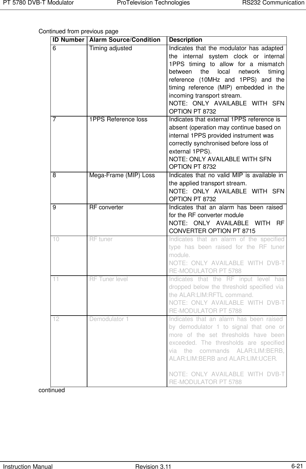
![PT 5780 DVB-T Modulator ProTelevision Technologies Contents Instruction Manual Revision 3.11 iii6.2.3.13 TEST commands ........................................................................6-23 6.2.3.14 FACTORY commands.................................................................6-24 6.3 COMMANDS SUMMARY ...........................................................................................6-25 6.3.1 Mandated Commands ...............................................................................6-25 6.3.2 Required commands .................................................................................6-25 6.3.2.1 SYSTem subsystem....................................................................6-25 6.3.2.2 STATus subsystem.....................................................................6-25 6.3.3 Instrument commands ...............................................................................6-26 6.3.3.1 DIAGnostic subsystem................................................................6-26 6.3.3.2 SYSTem subsystem....................................................................6-26 6.3.3.3 USER subsystem........................................................................6-26 6.3.3.4 DISPlay subsystem.....................................................................6-26 6.3.3.5 INPut subsystem.........................................................................6-27 6.3.3.6 OUTPut subsystem.....................................................................6-27 6.3.3.7 MONitor subsystem.....................................................................6-29 6.3.3.8 PRECorrect (Nonlinear Pre-corrector) subsystem .........................6-29 6.3.3.9 LPRecorrect (Linear Pre-corrector) subsystem..............................6-29 6.3.3.10 SFN subsystem ..........................................................................6-30 6.3.3.11 ALARm subsystem......................................................................6-30 6.3.3.12 EVENt subsystem.......................................................................6-31 6.3.3.13 TEST subsystem ........................................................................6-31 6.3.3.14 FACTory subsystem....................................................................6-31 6.4 ERROR CODES ......................................................................................................6-32 6.4.1 Command errors [-199, -100] .....................................................................6-32 6.4.2 Execution errors [-299, -200] ......................................................................6-33 6.4.3 Device specific errors [-399, -300] ..............................................................6-34 6.4.4 Query errors [-499, -400] ...........................................................................6-34 6.4.5 Device specific errors [1, 32468] ................................................................6-34 APPENDIX A…...........................................................................................….A-1 APPENDIX B………………………………………………………………………..A-2](https://usermanual.wiki/UBS-Axcera/LL200ATC.Pro-Television-Modulator-Model-PT5780-Manual/User-Guide-541456-Page-5.png)

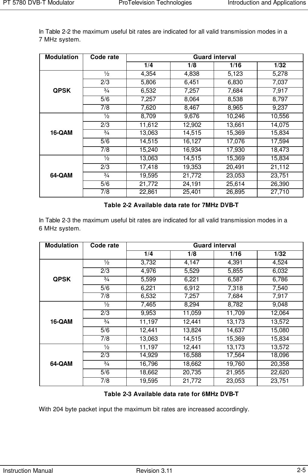

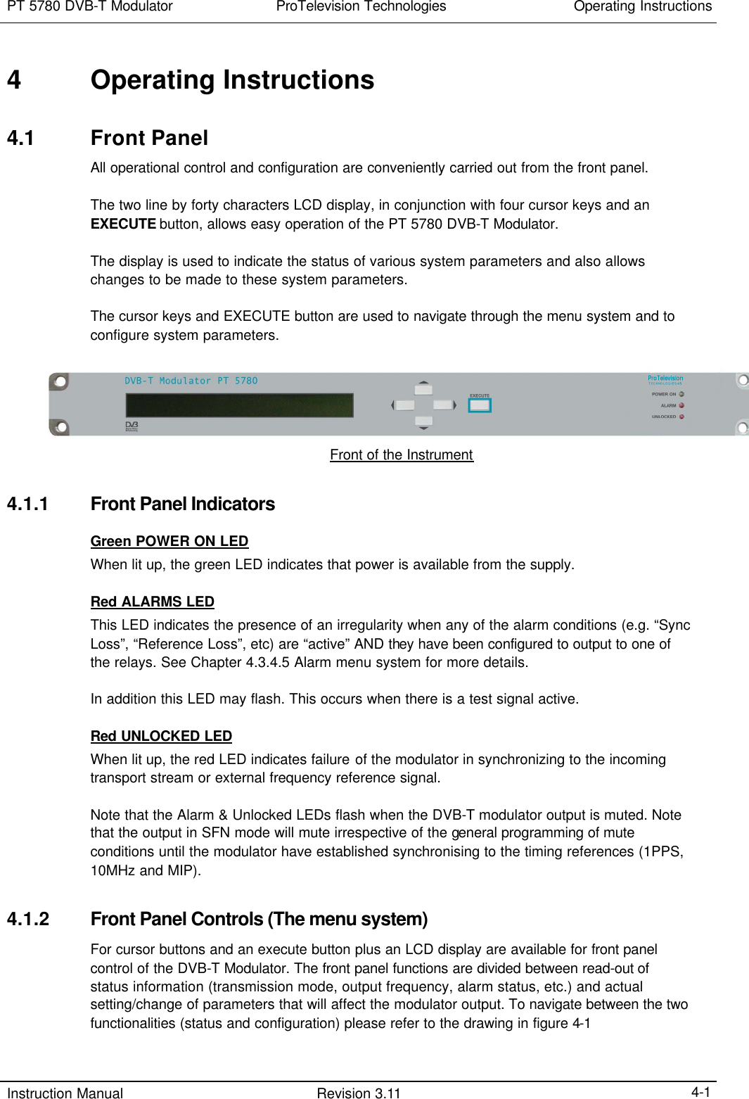
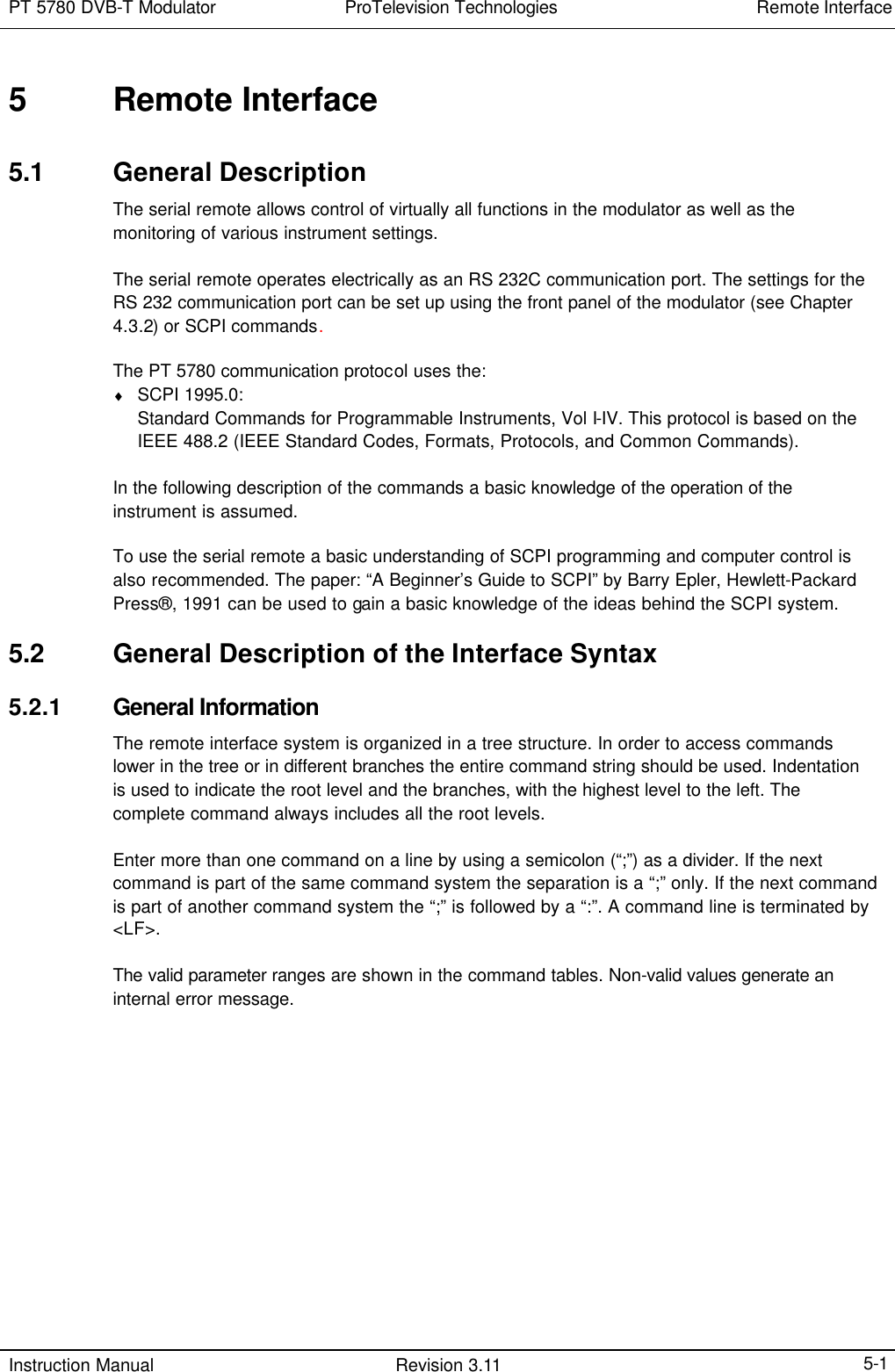
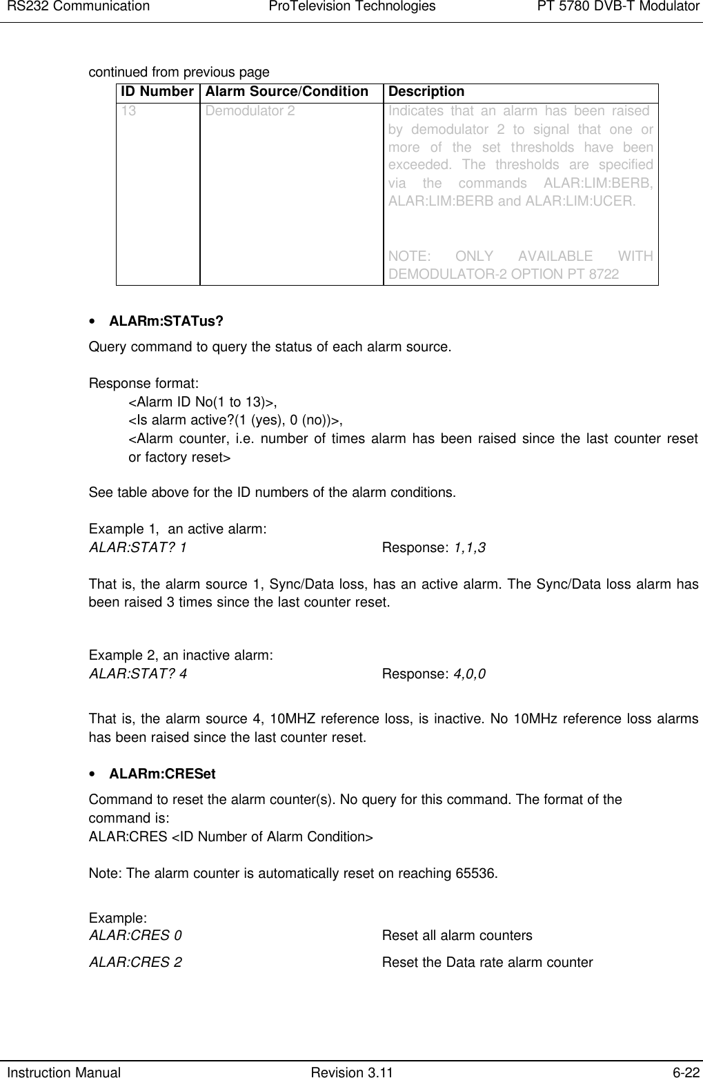
![Operating Instructions ProTelevision Technologies PT 5780 DVB-T Modulator Instruction Manual Revision 3.11 4-2 Status Menu SystemConfiguration Menu SystemPush [EXECUTE] buttonand [RIGHT ARROW] buttonin sequence to enter theConfiguration Menu System(note 1).Push [UP ARROW] buttonto return to the Status MenuSystem.Note 1: Activates the Configuration Menu System at the top-level default entry point (Menu ID 1000 - <TRANSMISSION>). Alternatively, by pushingthe [EXECUTE] key twice the Configuration Menu System will be activated at a sub menu relevant to the currently selected status display. Forexample, pushing [EXECUTE] twice when the Input Status display is active will open the configuration sub menu for control of input configurationRev 3.0 23.01.2003u/5780/work/manual v3/drawings/status and config system Figure 4-1 Front panel menu system Dependent on the specific function being operated via the front panel the cursor keys may have the following functions: The 55 button is used to either • Scroll through the different sub displays provided within the status menu system (refer to the enclosed Status Menu System diagram) • Exit the current menu and enter a higher-level menu • Increase alpha-numerical parameters • Abort confirmation of a change The 66 button is used to either • Scroll through the different sub displays provided within in the status menu system (refer to the enclosed Status Menu System diagram). • Exit the current menu and enter a sub-menu • Decrease alpha-numerical parameters • Abort confirmation of a change The 33 and 44 buttons are used to scroll between the main displays provided in the status menu system (refer to the enclosed Status Menu System diagram) and to scroll between the functions available in the configuration menu system.](https://usermanual.wiki/UBS-Axcera/LL200ATC.Pro-Television-Modulator-Model-PT5780-Manual/User-Guide-541456-Page-24.png)
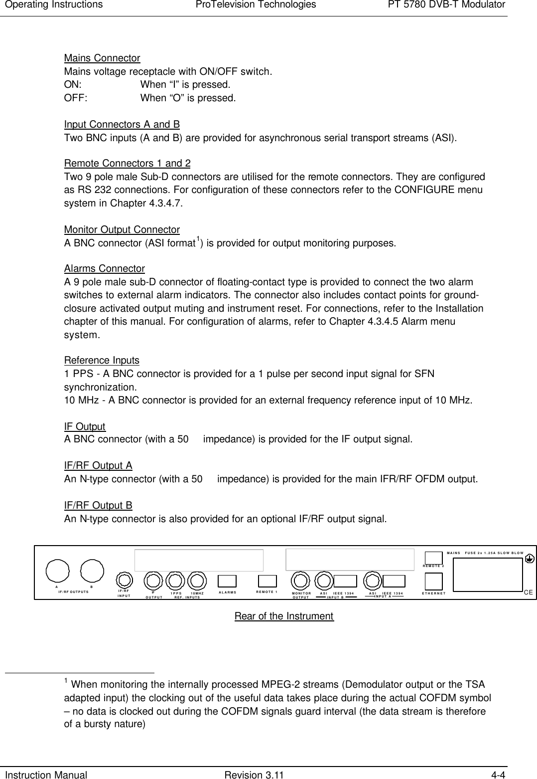
![PT 5780 DVB-T Modulator ProTelevision Technologies Operating Instructions Instruction Manual Revision 3.11 4-3 The EXECUTE button is used to • Enter the configuration menu system (GENERAL or SPECIFIC) when in the status menu system. • Confirm changes made to configurable parameters. 4.1.3 Front Panel Display To guide the user through operations, symbols of the push buttons, which are active at that particular time appear in the top right hand side of the display. 3and 4indicate that the left and right arrow buttons can be used; a 5indicates that the up button can be used; a 6 indicates that the down button can be used; a v indicates that both the up and down buttons can be used; and an E indicates that the EXECUTE button can be used. 55 66 33 44 Indicates which arrow buttons are active. E Indicates that the EXECUTE button must be pressed to activate the required selection. << >> These flashing brackets indicate the position of the cursor when in a menu option listing, also described as the “current” menu option in this manual. [ ] These flashing brackets indicate the position of the cursor when in a enumerated parameter listing or when in a parameter set listing. Also described as the “current” parameter in this manual. …… Indicates that more items are available in the menu option or parameter listing than can be fitted in the display. Scrolling right with the 4 button will display these items. Guide to Menu Display In addition, the top line of the display also usually shows the current menu option and status. The bottom line of the display indicates possible menu options or parameter settings. 4.2 Rear Panel 4.2.1 Rear Panel Connections Safety Ground (chassis)](https://usermanual.wiki/UBS-Axcera/LL200ATC.Pro-Television-Modulator-Model-PT5780-Manual/User-Guide-541456-Page-25.png)
![PT 5780 DVB-T Modulator ProTelevision Technologies Operating Instructions Instruction Manual Revision 3.11 4-5 This text is a site specific identification and can be modified by the customer via the Remote Interface only. The current date and time is displayed until the back-end controller is powered up. The software release is momentarily displayed before the modulator enters the first status window. 4.3 Menu System – Description and Operation The PT 5780 DVB-T Modulator is equipped with different functions dependent on the purchased options. An operating menu chart, which reflects the structure of the menu system when all possible functions are installed and enabled, is provided in appendix A.. The menu system is designed as a “tree” structure, with a number of different “branches”. Each “branch” is made up of a “menu options”. The lowest “branch” contains a configurable menu option with a list of parameters to choose from. Note that additional configurable options are available via remote access/control. See Chapter 6.2.3. The menu system has two main functions:- 1. system status display - the display of various modulator configuration settings through “status windows” 2. system configuration - the ability to modify the modulator’s configuration settings through “configuration windows”. On start up the modulator always enters the system status menu. There are two ways to enter the configuration menu system; by pressing [EXECUTE] followed by the [RIGHT] arrow button the configuration system will be opened at the top level entry point and the user will be able to navigate freely between all the menus. Alternatively, the user can press [EXECUTE] twice to open the menu system at a sub menu relevant to the status menu parameters being displayed when the key-press sequence is initiated. When using this navigation method pressing the [UP] arrow key will recall the last status display. 4.3.1 Power Up The start-up process includes the following status windows: ---------------------------------------- PT5780 DVB-T Modulator PTV - Power-up - 2001-07-08, 3:07:33 ---------------------------------------- And later: ---------------------------------------- PT5780 DVB-T Modulator PTV Release X.X ............................ ----------------------------------------](https://usermanual.wiki/UBS-Axcera/LL200ATC.Pro-Television-Modulator-Model-PT5780-Manual/User-Guide-541456-Page-27.png)
![PT 5780 DVB-T Modulator ProTelevision Technologies Operating Instructions Instruction Manual Revision 3.11 4-11 Additional information about each alarm can be obtained via the configuration sub menu <ALARM> –-> <ALARM INFORMATION> menu ID 3200 (accumulated count of the alarm type and specific information for generic alarms). The event log configuration menu <EVENTLOG> à <VIEW> menu ID 8100 may provide information abut the exact start and stop time for each type of alarm (requires that the alarm type has been routed to the event log by specifying Event Log “on” for the alarm type in the configuration sub menu <ALARM> –-> <DEFINE ALARM SYSTEM> menu ID 3100. If an alarm is “unstable” and alternates between being active and inactive AND the <CONFIGURE> – -> <AUTO OPEN ALARM WINDOW> (menu ID 5300) is set to “On” the alarm display will be opened automatically as explained above. However, to allow uninterrupted operation of the instrument via the front panel during repeated occurrence of an intermittent alarm the alarm window will not open until five seconds after the last key-press of any front panel key have taken place. Status Window ’h1’ – The Test Signal Status Window ---------------------------------------- TEST SIGNAL ACTIVE wv8E Single Carrier h1 ---------------------------------------- This status window displays the current test signal configuration and is only available if a test signal is active via the <TEST SIGNAL> – -> <SELECT TEST> sub menu Menu ID 6000. Note that the test signal menu is only available if the TEST SIGNAL lock in the sub menu <CONFIGURE> –-> <LOCK> menu ID 5100 is “OFF”. 4.3.4 Configuration Menu System Two methods for accessing the configuration menu system exist. The first step is always to push the [EXECUTE] button. This action will open the following display: ---------------------------------------- Entering Menus, Press Right Arrow wv8E or EXECUTE for specific... ---------------------------------------- note: the display will close automatically after about 3 seconds if the user does not press the [RIGHT ARROW] key or the [EXECUTE] key Top-level menu access Pressing the [RIGHT ARROW] button during the above display mode will open the configuration menu system at the default entry point (Transmission parameters, menu ID 1000). For further details see paragraph 4.3.4.1 Context sensitive menu access Pressing the [EXECUTE] button during the above display mode will open directly the configuration sub menu that is related to the status menu window in which the activation of the configuration menu system was initiated. For further details see paragraph 4.3.4.2. Note: when entering the menu system via the context sensitive method it’s not possible to navigate to a different menu without first exiting the configuration menu system (pressing the [UP] arrow key).](https://usermanual.wiki/UBS-Axcera/LL200ATC.Pro-Television-Modulator-Model-PT5780-Manual/User-Guide-541456-Page-33.png)
![Operating Instructions ProTelevision Technologies PT 5780 DVB-T Modulator Instruction Manual Revision 3.11 4-12 4.3.4.1 Top-level configuration menu access To enter the configuration menu at the top level of the menu hierarchy press the [EXECUTE] button followed by the [RIGHT ARROW] button. After pressing the [EXECUTE] button the below display will be shown. If the [RIGHT ARROW] button is not pressed within about 3 seconds the display will close automatically and return to the last open status window. ---------------------------------------- Entering Menus, Press Right Arrow wv8E or EXECUTE for specific... ---------------------------------------- The <TRANSMISSION> menu (ID 1000) is the top-level entry point in the menu hierarchy. The complete hierarchy is provided in the attached menu structure diagrams. All menu windows in the configuration menu system contain a four-digit number in the top right hand position. This number is known as the menu identification number and is useful for referencing purposes. The menu-structure has a maximum of four levels; hence the four-digit identification. See examples below. Examples of the top level of the configuration menu system are shown below in Examples A and B. The character string “DVB-T Modulator“ is always positioned on the left hand side of the display when in the top level of the configuration menu system. The available menu items are shown on the second line and may be scrolled through using the 33 and 8 buttons. The “current” menu option is always shown in capitalised format with flashing “< >” brackets. If more menu options are possible than the display allows, three (3) dots are shown in the lower right position. Example A ---------------------------------------- DVB-T Modulator <1000>wv8 <TRANSMISSION> Signal Alarm Preset ... ---------------------------------------- Pressing8 produces Example B: ---------------------------------------- DVB-T Modulator <2000>wv8 <SIGNAL> Alarm Preset Configure Te... ---------------------------------------- Moving down a level to the next menu option by pressing the 66 button produces a display like that shown in Example C. Example C ---------------------------------------- Signal, Input [2110: ON]wv8 <AUTO SUBSTITUTION> Input ---------------------------------------- The “current” parameter is shown in the top right hand side of the display together with the menu identification number, which is surrounded by square brackets. If the parameter name is](https://usermanual.wiki/UBS-Axcera/LL200ATC.Pro-Television-Modulator-Model-PT5780-Manual/User-Guide-541456-Page-34.png)
![PT 5780 DVB-T Modulator ProTelevision Technologies Operating Instructions Instruction Manual Revision 3.11 4-13 longer then 8 characters, the name is truncated and a dot (.) is included as the 8th character. In a few cases, the “current” parameter is automatically updated in the display window, e.g. the Clock. The lowest level of any particular “branch” of the menu system produces a window that displays the available parameter list, a configurable value or a non-configurable value. At this level the only information given in the upper right hand corner is the menu identification number. If a parameter list is obtained (see Example D), the “current” parameter is always the first item and is capitalised and surrounded by flashing square brackets. Example D ------------------------------------------- Signal, Input, Auto Substitute <2110>w58E [ON] off ------------------------------------------- If an editable value is accessed (see Example E) the current parameter value is shown in the bottom left hand side of the display. The last digit of the “current” parameter value flashes to indicate that this digit will be changed if the [UP] or [DOWN] keys are pressed. The other digits of the value can be edited by navigating to the digit using the [LEFT] or [RIGHT] keys. The valid range for the parameter is indicated in square brackets in the bottom right hand side of the display. Example E ---------------------------------------- Sig.Out. RF Level (dB) <2250>wv8E 00,0 [-10.0 ..0.0] ---------------------------------------- Finally if a non-configurable parameter value is accessed the window shown in Example F is displayed. The menu parameter is enclosed in and brackets, whilst the “current” parameter value is shown in the upper right hand corner of the menu window, with no brackets. Example F ---------------------------------------- Instrument Identity 123456 w58 INSTRUMENT KU NUMBER ---------------------------------------- 4.3.4.2 Context sensitive menu access To use the context sensitive menu access press the [EXECUTE] button twice. After the first pressing of the EXECUTE button the below window will open. If the EXECUTE button is not pressed a second time within about 3 seconds the window will close automatically and return to the last open status window. ---------------------------------------- Entering Menus, Press Right Arrow wv8E or EXECUTE for specific... ----------------------------------------](https://usermanual.wiki/UBS-Axcera/LL200ATC.Pro-Television-Modulator-Model-PT5780-Manual/User-Guide-541456-Page-35.png)
![Operating Instructions ProTelevision Technologies PT 5780 DVB-T Modulator Instruction Manual Revision 3.11 4-14 The context sensitive access to the configuration system will open directly the configuration sub menu that is related to the status menu window in which the activation of the configuration menu system is initiated. For example, pressing [EXECUTE] à [EXECUTE] when the “Input status” display is active will open the <SIGNAL> à <INPUT> sub menu for configuration of input source. Likewise, pressing [EXECUTE] à [EXECUTE] when the “output status” display is active will open the <SIGNAL> à <OUTPUT> sub menu for configuration of frequency, level, etc. Status menu Associated configuration menu (accessed by pressing [EXECUTE] à [EXECUTE]) Input Status (a1, a2) <SIGNAL> <INPUT> menu ID 2120 Mode Status (b1) <TRANSMISSION> <MODE> menu ID 1200 TS Buffer fill (c1 - MFN) <TRANSMISSION> menu ID 1000 TS Control Status (c2 – SFN) <TRANSMISSION> <SFN TS Control> menu ID 1100 Optional Time, Freq,(c3 –SFN) <TRANSMISSION> <SFN TS Control> menu ID 1100 Output Status (d1) <SIGNAL> <OUTPUT> menu ID 2200 Pre-Corrector status (d2) <SIGNAL> <Non-Lin Pre-Corrector> menu ID 2300 Alarm status (g1) <ALARM> <DEFINE ALARM SYSTEM> menu ID 3100 Table 4-1 Context sensitive menu access 4.3.4.3 TRANSMISSION Menu System (Menu ID 1000) The top level of the transmission menu system (menu ID 1000) is accessed by pressing the [EXECUTE] button followed by the [RIGHT ARROW] button as described in paragraph 4.3.4.1. By applying the [LEFT] , [RIGHT] , [UP] , [DOWN] keys as required (see attached Configuration Menu System diagram) it is possible to navigate to a number of sub menus: SFN TS Control (ID 1100) This menu, which is only available when the instrument is configured for SFN mode, allows the user to select if the transmission parameters (constellation, guard interval, code rate, hierarchy) are to be controlled via the MIP (default setting) or if the parameters are to be set manually. If the manual mode is selected it is the operators responsibility to ensure that the selected parameters correspond to the parameters applicable to the transport stream to be transmitted. If the manually selected parameters do not match those applicable to the applied transport stream transmission in SFN mode is not possible (output will be muted). MODE (ID 1200) This menu allows the user to select the COFDM parameters for the transmission. Sub menus are available for setting Hierarchy (if hierarchical option is installed), IFFT, Code rate constellation and guard interval. The mode menu cannot be accessed if SFN TS control is set to “ON”.](https://usermanual.wiki/UBS-Axcera/LL200ATC.Pro-Television-Modulator-Model-PT5780-Manual/User-Guide-541456-Page-36.png)
![PT 5780 DVB-T Modulator ProTelevision Technologies Operating Instructions Instruction Manual Revision 3.11 4-15 MFN/SFN (ID 1300) The menu allows selection of the network mode to be applied for the transmission; Multi Frequency Network – MFN or Single Frequency Network – SFN. Note: The menu is only accessible when the SFN option PT 8732 is installed. 4.3.4.4 SIGNAL Menu System (Menu ID 2000) The signal menu system (menu ID 2000) is accessed by pressing the [EXECUTE] button followed by the [RIGHT ARROW] button as described in paragraph 4.3.4.1. When the menu system is entered at menu TRANSMISSION use the [RIGHT ARROW] button to navigate to the SIGNAL menu. INPUT menu (ID 2100) This menu allows the user to select the input source(s) and to set the status of the auto substitution function. In the non-hierarchical configuration the input menu (ID 2120) allows the user to assign a primary input source and a secondary input source. The instrument offers as standard a choice between two input sources (ASI input “A” and ASI input “B” corresponding to the BNC input sockets located in the rear panel of the modulator). Additional input sources such as two more ASI inputs (input “C” and “D” ) or an SPI LVDS input are available as options (When installed the SPI LVDS input is identified as input “C”). For non-hierarchical applications the user will typically program input ”A” as the “primary” and input “B” as the “secondary” input source. Should the “primary” signal source fail in this configuration the instrument will automatically switch over to the “secondary” input if the Auto substitution function is set to “ON” (requires that a valid MPEG-2 transport stream is applied to the “secondary” input). For hierarchical applications the user will typically assign input “A” as primary source for the High Priority input (Menu ID 2120) and assign input “B” as primary source for the Low Priority input (menu ID 2130). If the option that provides two additional ASI inputs is installed (Input “C” and “D”) the user may choose to program Input C as secondary input source for the High Priority input (menu ID 2120) and to program Input D as secondary input source for the Low Priority input (menu ID 2120) if it desired to add redundancy by means of the Auto Substitution function. That is, when the auto substitute function is set to “ON” the unit will automatically switch to the secondary input source if the primary input source fails (requires that a valid MPEG-2 transport stream is applied to the “secondary” input). OUTPUT (ID 2000) This menu allows the user to set a range of parameters that affect the generated COFDM spectrum. Sub menus are available for setting (centre) frequency, bandwidth, level, sideband filter (window) function, spectrum polarity, and local transmission delay (SFN only). A sub menu (menu ID 2210) allows the user to set the output frequency. The IF version allows setting of the frequency in the range between 35-37MHz. The RF version covers the range from 30MHz to 1000MHz. Note: In case of the RF version (option PT 8715 installed) the IF output is fixed to 36MHz. The RF version allows furthermore the user to set the output frequency by channel number (menu ID 2220). The applicable channel raster is programmable via the channel set-up menu (menu ID 2230). The channel set-up menu offers selection between a](https://usermanual.wiki/UBS-Axcera/LL200ATC.Pro-Television-Modulator-Model-PT5780-Manual/User-Guide-541456-Page-37.png)
![Operating Instructions ProTelevision Technologies PT 5780 DVB-T Modulator Instruction Manual Revision 3.11 4-18 Reference input (ID 2600) This menu allows the user to select the 10MHz clock reference source and to configure parameters with respect to the 10MHz and 1PPS reference inputs. Sub menus are available for selecting 10MHz source (menu ID 2610), impedance for the 1PPS reference input (menu ID 2620), impedance for the 10MHz reference input (menu ID 2630), and trigger level for the 1pps input. The 10MHz reference source can be set to Internal, External or Auto. By auto mode the unit will synchronize to an external reference if available and automatically switch to the internal reference if no external reference is available (no alarm will be raised if the unit switches to internal reference). By external reference mode the unit will synchronize to an external 10MHz when available and switch to the internal reference if no external reference is available (an alarm will be raised if the unit in this mode needs to switch to internal reference due to absence of external reference). Note: for SFN mode external reference should be selected. 4.3.4.5 ALARM Menu System (Menu ID 3000) The alarm menu system (menu ID 3000) is accessed by pressing the [EXECUTE] button followed by the [RIGHT ARROW] button as described in paragraph 4.3.4.1. When the menu system is entered at menu TRANSMISSION use the [RIGHT ARROW] button to navigate to the Alarm menu. Define Alarm menu (ID 3100) This menu allows the user to program the desired response for each of the possible alarms that can be raised by the unit. For each type of alarm the user can choose to route the alarm to one or several of the following destinations: Alarm destination Description Mute When the Mute option for an alarm is set to “ON” the alarm will be routed to the mute control circuit. In this case the modulator output will mute whenever the alarm is active. Event Log When the Event Log option for an alarm is set to “ON” the alarm will be routed to the Event Log. In this case the time and date when the alarm is raised and the time and date when the alarm is lowered will be recorded in the event log together with the specific name of the alarm type. Relay 1 When the Relay 1 option for an alarm is set to “ON” the alarm will be routed to Alarm 1 relay control circuit. In this case the Alarm 1 relay contacts will be activated whenever the alarm is active. The red ALARM led located in the front panel will be on for the duration of the alarm. Relay 2 When the Relay 2 option for an alarm is set to “ON” the alarm will be routed to Alarm 2 relay control circuit. In this case the Alarm 2 relay contacts will be activated whenever the alarm is active. The red ALARM led located in the front panel will be on for the duration of the alarm.](https://usermanual.wiki/UBS-Axcera/LL200ATC.Pro-Television-Modulator-Model-PT5780-Manual/User-Guide-541456-Page-40.png)
![PT 5780 DVB-T Modulator ProTelevision Technologies Operating Instructions Instruction Manual Revision 3.11 4-27 located at lowest frequency). Selectable settings are Normal and Inverted (carrier 1 located at highest frequency). 4.3.4.10 EVENT LOG Menu System (Menu ID 8000) The event log menu system allows the user to observe the recorded events (sub menu ID 8100) and to clear the event log (sub menu ID 8200). When entering the event log system the menu will in addition to the two choices <VIEW> and <CLEAR> indicate the total number of events recorded since the event log was cleared. ---------------------------------------- Event log [8100: 67 Events] wv8 <VIEW> Clear --------------------------------------- When entering the event log VIEW display the last recorded event is displayed. The first display line indicates the event number and the time and date for the event. The second display line shows the identification number and name for the recorded event type plus when applicable additional information concerning the event. ---------------------------------------- Event 67 2003-01-24, 17:34:36 wt8E 2240 Sync Unlock, HP ----------------------------------------------------------------------- By pressing the [LEFT] or [RIGHT] button the other events recorded in the log can be observed one-by-one. When pressing the [RIGHT] button when observing the last recorded event the display will wrap around to the first event which will always be the “log cleared” event: ----------------------------------------- Event 0 2003-01-15, 16:44:43 wt8E 1411 Log Cleared, No info ------------------------------------------------------------------------ 4.3.5 Configuring Parameters 4.3.5.1 Selection from Enumerated Values ---------------------------------------- Signal, Input, HP, Primary <2121>w58E [DEMODULATOR] Inp A Inp B Inp C In... ---------------------------------------- (the square brackets flash at approx. 2 Hz) The current value is shown as the first item in the list, in capitalised format and in square brackets. Navigating: w Scrolls the previous item into the “current position”. 8 Scrolls the next edit item into the “current position”. 66 No effect. 5 Aborts editing and moves up one menu level. <EXECUTE> Saves the “current” item as the active parameter and returns to the menu level above.](https://usermanual.wiki/UBS-Axcera/LL200ATC.Pro-Television-Modulator-Model-PT5780-Manual/User-Guide-541456-Page-49.png)
![Operating Instructions ProTelevision Technologies PT 5780 DVB-T Modulator Instruction Manual Revision 3.11 4-28 4.3.5.2 Editing of Numerical Values ---------------------------------------- Cfg. TX Ident <5800>wv8E 65,335 [0..65,535] ---------------------------------------- (the character 5 alternates between ‘5’ and ‘_’ at approximately 2 Hz) The configurable value that appears on the display is always the current value and the cursor is always initially positioned on the last digit. The valid range is displayed in square brackets on the bottom line’s right hand side. Navigating: w Positions the cursor on the previous character. Jumps to the last character when the cursor is on the first. 8 Positions the marker on the next character. Jumps to the first character when the marker is on the last. 66 Decrements the value at the cursor’s position. If the value is ‘0’, using the 66 button causes the value to change to ‘9’. If the value can be a negative number, using the 66 button in the first character space toggles between the negative sign (-) and a blank (positive). 5 Increments the value at the cursor’s position. If the value is ‘9’, using the 5 button causes the value to change to ‘0’. If the value can be a negative number, using the 5 button in the first character space toggles between the negative sign and a blank (positive). EXECUTE Completes editing. Note that if a numerical configurable item has a minimum and/or maximum value, the user cannot modify the value to below the minimum or above the maximum values. If the value has been modified, the following window will be displayed on pressing the EXECUTE button, requesting validation: ---------------------------------------- SAVE Changes? (YES=execute)wv8E 60,000 [0..65,535] ---------------------------------------- (the character = flashes at approximately 2 Hz) Again, the valid range is displayed in square brackets on the bottom line’s right hand side. Navigating: w Aborts any changes made and moves up one menu level. 8 Aborts any changes made and moves up one menu level. 66 Aborts any changes made and moves up one menu level. 5 Aborts any changes made and moves up one menu level. EXECUTE Saves the edited value to memory and returns to the menu level above. 4.3.5.2.1 Instantly Updated Parameters In some cases the parameter is updated instantly in the hardware as the changes are made to a parameter. These menu options are characterised by a flashing ‘E’ whilst in the display of the configurable value.](https://usermanual.wiki/UBS-Axcera/LL200ATC.Pro-Television-Modulator-Model-PT5780-Manual/User-Guide-541456-Page-50.png)
![PT 5780 DVB-T Modulator ProTelevision Technologies Operating Instructions Instruction Manual Revision 3.11 4-29 ---------------------------------------- Sig. Out. RF Level (dB) <2250>wv8E -0.07 [-10.0 .. 0.0] ---------------------------------------- (the characters ‘E’ and ‘7’ flash at approximately 2 Hz) In this case all the buttons perform the same functions as when editing a configurable value. Important: As the parameter is instantly updated in the hardware, if it has been modified and there is a power outage or the CONFIGURE – AUTO ESCAPE MENU is set to “On” and the display times out (see Chapter 4.3.4.7) the new value will be automatically retained. If the value has been modified and the EXECUTE button is depressed, the following window will be displayed, requesting confirmation: ---------------------------------------- CONFIRM Changes? (YES=execute)wv8E -0.05 [-10.0 .. 0.0] ---------------------------------------- (the characters ‘E’ and ‘=’ flash at approximately 2 Hz) As before, all buttons perform the same functions as when saving a change and again if the display times out or there is a power outage the new value will be retained. 4.3.5.3 Editing of Text ---------------------------------------- Preset, Name: #1 <4310>wv8E Hove Tx 12 ---------------------------------------- (the character ‘H’ alternates between ‘H’ and ‘_’ at approximately 2 Hz) The current text string is shown as the editable value. The characters A..Z, a..z, 0..9, - (minus), _(underscore) and “ “(space) are supported. Navigating: w Positions cursor on previous character. 8 Positions cursor on next character. 66 Decrements the current edit item in a circular manner. 5 Increments the current edit item in a circular manner. EXECUTE Completes editing. If the text has been changed, the following window will be displayed requesting validation: ---------------------------------------- SAVE Changes? (YES=execute)wv8E Preset 2 ---------------------------------------- (the character ‘=’ flashes at approximately 2 Hz)](https://usermanual.wiki/UBS-Axcera/LL200ATC.Pro-Television-Modulator-Model-PT5780-Manual/User-Guide-541456-Page-51.png)
![PT 5780 DVB-T Modulator ProTelevision Technologies Remote Interface Instruction Manual Revision 3.11 5-3 The instrument will always send the response data in capitals. Headers are not sent in the response messages, only the parameters. 5.2.4 Long and Short Form Program messages may be sent in either long or short form. ♦ The long form is the full word ♦ The short form is usually the first four characters of the long form The short form in a syntax specification is shown in upper case, and the remaining part of the long form is shown in lower case characters. Note: Upper and lower case, as used in syntax specification, is only a notation habit to facilitate distinction between long and short form. The instrument itself does not differentiate between upper and lower case characters. In program messages, either the long or short form may be used in any mix of upper or lower case characters. There is no semantic difference between upper and lower case in program messages. 5.2.5 Syntax Elements ; Semicolon separates two commands on a command line and does not change the path. : Colon separates the keywords of a command. In a command line, a colon “:” after a separating semicolon “;” indicates the root control level. Moves down for level. , Comma separates parameters. ?? Question mark identifies a query command. (Query commands are formed by adding a question mark to the header command). * Asterisk identifies a common command. (Common commands consists of a header command preceded by an asterisk and possibly followed by one or more parameters) ’ or ” Single or double quote introduces and terminates a character string. Space Space character separates the command header and parameters. | Parameters divided by a “|” indicates an “or” selection between the values shown. Only one value may be used at a time. [xxxx] Square brackets indicate an optional specific string parameter used by some command systems.](https://usermanual.wiki/UBS-Axcera/LL200ATC.Pro-Television-Modulator-Model-PT5780-Manual/User-Guide-541456-Page-57.png)

![RS232 Communication ProTelevision Technologies PT 5780 DVB-T Modulator Instruction Manual Revision 3.11 6-2 • *SRE SERVICE REQUEST ENABLE The device accepts this command but does not act on it. • *SRE? SERVICE REQUEST ENABLE QUERY The device accepts this query command but does not act on it. Note that this query command responds with a “0”. • *STB? READ STATUS BYTE QUERY The device accepts this query command but does not act on it. Note that this query command responds with a “0”. • *TST? SELF-TEST QUERY The device accepts this query command but does not act on it. • *WAI WAIT TO CONTINUE The device accepts this command but does not act on it. 6.2.2 Required Commands Required commands are those that required in all SCPI compliant instruments. 6.2.2.1 SYSTem commands • SYSTem:ERRor? Query command for reading an SCPI error message from the error queue. See Chapter 6.4 for a complete list of error codes. Example: SYST:ERR? Response: -102,”Syntax error” • SYSTem:VERSion? Query command for reading the SCPI version to which the RS232 implementation complies. Example: SYST:VERS? Response: 1995.0 6.2.2.2 STATus commands • STATus:OPERation[:EVENt]? The device accepts this command but does not act on it. • STATus:OPERation:CONDition? The device accepts this query command but does not act on it. • STATus:OPERation:ENABle The device accepts this command but does not act on it. • STATus:QUEStionable[:EVENt]? The device accepts this query command but does not act on it. • STATus: QUEStionable:CONDition? The device accepts this query command but does not act on it.](https://usermanual.wiki/UBS-Axcera/LL200ATC.Pro-Television-Modulator-Model-PT5780-Manual/User-Guide-541456-Page-60.png)
![PT 5780 DVB-T Modulator ProTelevision Technologies RS232 Communication Instruction Manual Revision 3.11 6-3 • STATus: QUEStionable:ENABle The device accepts this command but does not act on it. • STATus: PRESet The device accepts this command but does not act on it. 6.2.3 Instrument Commands 6.2.3.1 DIAGnostic commands • DIAGnostic:DISPlay The device accepts this command but does not act on it. • DIAGnostic:ERRorqueue:RESet The device accepts this command but does not act on it. Command to reset the internal error queue of the modulator. The error queue is a circular queue consisting of a number of entries. • DIAGnostic:ERRorqueue? The device accepts this command query but does not act on it. Command to read an entry in the error queue and point to next entry in the error queue. This command should be executed five times to read the complete error queue. 6.2.3.2 SYSTem commands • SYSTem:PRESet[:RECall] Command to recall a stored modulator configuration from a preset. The configuration settings that a preset saves are listed in Chapter 4.3.4.6. There are 10 user presets, from 1 to 10, available. Example: SYST:PRES:REC 3 Recall preset 3 in the modulator SYST:PRES:REC? Response: 3, i.e. preset 3 is currently active • SYSTem:PRESet:STORe Command to store the present modulator configuration in a preset. Ten user presets from 1 to 10 are available. There is no equivalent query command. Example: SYST:PRES:STOR 2 Store configuration in preset 2 • SYSTem:PRESet:NAMe Command for naming these user presets. Ten user presets from 1 to 10 are available. The number of characters in the name are limited to sixteen (16). Example: SYST:PRES:NAME 2,”WHAT” Name preset number 2 “WHAT” SYST:PRES:NAME? 2 Response: “WHAT”](https://usermanual.wiki/UBS-Axcera/LL200ATC.Pro-Television-Modulator-Model-PT5780-Manual/User-Guide-541456-Page-61.png)
![PT 5780 DVB-T Modulator ProTelevision Technologies RS232 Communication Instruction Manual Revision 3.11 6-25 6.3 Commands Summary All commands listed consist of both a set and request command unless specifically listed in the table. 6.3.1 Mandated Commands Command Parameter Status after Factory Reset Remarks *CLS *ESE No action *ESE? No action *ESR? No action *IDN? *OPC No action *OPC? No action *RST *SRE No action *SRE? No action *STB? No action *TST? No action *WAI No action 6.3.2 Required commands 6.3.2.1 SYSTem subsystem Command Parameter Status after Factory Reset Remarks :ERRor? Query only :VERSion? Query only 6.3.2.2 STATus subsystem Command Parameter Status after Factory Reset Remarks :OPERation [:EVENt]? Query only. No action :CONDition? Query only. No action :ENABle 0 to 65535 No action :QUEStion [:EVENt]? Query only. No action :CONDition? Query only. No action :ENABle No action :PRESet No action](https://usermanual.wiki/UBS-Axcera/LL200ATC.Pro-Television-Modulator-Model-PT5780-Manual/User-Guide-541456-Page-83.png)
![RS232 Communication ProTelevision Technologies PT 5780 DVB-T Modulator Instruction Manual Revision 3.11 6-26 6.3.3 Instrument commands 6.3.3.1 DIAGnostic subsystem Command Parameter Status after Factory Reset Remarks :DISPlay - No query. No action :ERRorqueue? - - Query only. No action :ERRorqueue :RESet - - No query. No action 6.3.3.2 SYSTem subsystem 6.3.3.3 USER subsystem Command Parameter Status after Factory Reset Remarks :NAMe <”Name”> String data 6.3.3.4 DISPlay subsystem Command Parameter Status after Factory Reset Remarks :CONTrast 0 to 100 % 25 Command Parameter Status after Factory Reset Remarks :PRESet [:RECall] 1 to 10 - :STORe 1 to 10 - No query. :NAMe 1 to 10,<”Name”> - Name – string data format. Query command format is :PRES:NAME? <System Preset No. 1 to 10>. :DATE <YYYY,MM,D> 2002,01,01 :TIME <HH,MM,SS> 00,00,00 :OINStalled <”xxxx.xxxx.xxxx.xxxx”> String data format :OUSed <”101001….”> String data format consisting of 1’s and 0’s :COMMunicate: SERial:TRANsmit:BAUD <Port no.>,<Baudrate> 1 | 2 , 1200 | 2400 | 4800 | 9600 | 19200 | 115200 On both ports - 19200 :FRES See Chap. 4.4 No query.](https://usermanual.wiki/UBS-Axcera/LL200ATC.Pro-Television-Modulator-Model-PT5780-Manual/User-Guide-541456-Page-84.png)
![RS232 Communication ProTelevision Technologies PT 5780 DVB-T Modulator Instruction Manual Revision 3.11 6-28 Command Parameter Status after Factory Reset Remarks :IF :FREQuency 35 to 37 MHz 36 MHz Only in IF version. Step size of 1Hz. Query only in RF version. :LEVel -2.0 to 8.0 dB 0.0 Only in IF version. Step size of 0.1dB. Query only in RF version. :RF :FREQuency 30 to 1000 MHz 474 MHz Only in RF version. Step size of 1Hz. :LEVel -10.0 to 0.0 dB 0.0 Only in RF version. Step size of 0.1dB. :FREQuency 35 to 37MHz (if IF version) 30 to 1000 MHz (if RF version) 36 MHz (if IF version) 474 MHz (if RF version) :LEVel -2.0 to 8.0 dB (if IF Version) -10.0 to 0.0 dB (if RF version) 0.0 :BANDwidth 6 | 7 | 8 MHz 8 :CRASter IUHF | IVHF | IUVH | UCH (short form) IUHF | IVHF | IUVHF | UCHANNEL (long form) IUHF Only in RF version. The corresponding query replies are: IUHF | IVHF | IUVHF | UCHANNEL :VSUB VHFB | VHFL | VHFI VHFB Only in RF version and VHF raster is selected. :UCDefinition <Start channel>, <Base frequency> Start = 21, Base freq = 470 MHz Only in RF version and user defined raster is selected. :CHANnel Dependent on channel raster: IUHF: 21 to 69 | IVHF & VHF(L): 0 to 5 | IVHF & VHF(B): 5 to 12 | IVHF & VHF(I): 1 to 6 | UCH: 0 to 99 21 (ITU UHF) Only in RF version. :WINDow? Query only [:ENABle] OFF | ON ON :ROLLoff W1_64 | W1_128 | W1_256 | W1_512 W1_64 :POLarity NORMal | INVerted NORMal :PEAK :CLIPping -10.0 to 0.0 dB 0.0 Steps of +0.5dB](https://usermanual.wiki/UBS-Axcera/LL200ATC.Pro-Television-Modulator-Model-PT5780-Manual/User-Guide-541456-Page-86.png)
![RS232 Communication ProTelevision Technologies PT 5780 DVB-T Modulator Instruction Manual Revision 3.11 6-32 6.4 Error Codes 6.4.1 Command errors [-199, -100] Error Number Error string [description/explanation/example] -100 Command error The command is invalid or incorrect. -101 Invalid character A command or parameter contains an invalid character, e.g. a header containing an ampersand, SYST:VERS&. -102 Syntax error An unrecognised command or data type was encountered, e.g. a string was received when the generator did not accept strings. -103 Invalid separator A separator was expected, but an illegal character was encountered, e.g. the semicolon was omitted after a command, *IDN?:SYST:ERR?; -104 Data type error A data element different than one allowed was encountered, e.g. numeric data was expected but string data was encountered. -108 Parameter not allowed More parameters was received than expected for the command, e.g. the *IDN?; command accepts no parameters, so receiving *IDN? 2; is not allowed -109 Missing parameter Fewer parameters were received than expected for the command. -110 Command header error An error was detected in the command header. -111 Header separator error A character which is not a legal header separator was encountered, e.g. no white space followed the header, thus SYST:PRES:NAME”MACRO” is an error. -112 Program mnemonic too long The header contains more than twelve characters. -113 Undefined header The header is syntactically correct, but is not defined for the device. -114 Header suffix out of range The command is invalid because the value of the numeric suffix attached to the program mnemonic is out of range, e.g. OUTP:ALAR3? is illegal because only 2 alarm outputs exists. -120 Numeric data error An error in the numeric data was encountered. -121 Invalid character in number An invalid character for the data type was encountered, e.g. an alpha in a decimal value. -123 Exponent too large The magnitude of the exponent was larger than 32000. -124 Too many digits The mantissa of a decimal numeric data element contained more than 255 digits. -125 Numeric data not allowed A legal numeric data was received, but the device does not accept one. -130 Suffix error An error in the suffix was encountered.](https://usermanual.wiki/UBS-Axcera/LL200ATC.Pro-Television-Modulator-Model-PT5780-Manual/User-Guide-541456-Page-90.png)
![PT 5780 DVB-T Modulator ProTelevision Technologies RS232 Communication Instruction Manual Revision 3.11 6-33 Error Number Error string [description/explanation/example] -131 Invalid suffix The suffix is syntactically incorrect. -134 Suffix too long The suffix contains more than twelve characters. -138 Suffix not allowed A suffix was encountered after a numeric element that does not allow suffixes. -140 Character data error An error in the character was encountered. -150 String data error An error in the string data was encountered. -151 Invalid string data A string data element was expected, but was invalid for some reason, e.g. an END message was received before the terminal quote character. -158 String data not allowed A string data element was received but was not allowed by the device. -160 Block data error There is an error in the block data received. -161 Invalid block data A block data was expected, but was invalid for some reason. -170 Expression error There is an error in the expression received. 6.4.2 Execution errors [-299, -200] Error Number Error string [Description/explanation/example] -200 Execution error -203 Command Protected Indicates that a legal protected program command or query could not be executed because the command was disabled. -220 Parameter error Indicates that a program data element related error occurred. -222 Data out of range Indicates that a legal program data element was received but could not be executed because the interpreted values was outside the range as defined by the device, e.g. the command OUTP:GAIN 5; is illegal since the gain cannot exceed 3 dB. -223 Too much data Indicates that a legal program data element of block, expression, or string type was received that contained more data than the device could handle due to memory or related device-specific requirements. -224 Illegal parameter value Used where exact value, from a list of possible, was expected. -233 Invalid version Indicates that a legal program data element was parsed but could not be executed because the version of the data is incorrect to the device.](https://usermanual.wiki/UBS-Axcera/LL200ATC.Pro-Television-Modulator-Model-PT5780-Manual/User-Guide-541456-Page-91.png)
![ProTelevision Technologies PT 5780 DVB-T Modulator Instruction Manual Revision 3.11 6-34 Error Number Error string [Description/explanation/example] -241 Hardware missing Indicates that a legal program command or query could not be executed because of missing device hardware. 6.4.3 Device specific errors [-399, -300] Error Number Error string [Description/explanation/example] -300 Device-specific error -350 Queue overflow A specific code entered into the queue in lieu of the code that caused the error. This code indicates that there is no room in the queue and an error occurred but was not recorded. -360 Communication error A communication error on the serial port was detected -361 Parity error in program message Parity bit not correct when data received on the serial port -362 Framing error in program message A stop bit was not detected when data was received, e.g. a bad rate mismatch. -363 Input buffer overrun Software or hardware input buffer on serial port overflows. 6.4.4 Query errors [-499, -400] Error Number Error string [Description/explanation/example] -400 Query error An error occurred during a query. -410 Query INTERRUPTED Indicates that a condition causing an INTERRUPTED Query error occurred. -420 Query UNTERMINATED Indicates that a condition causing an UNTERMINATED Query error occurred. -430 Query DEADLOCKED Indicates that a condition causing an DEADLOCKED Query error occurred. 6.4.5 Device specific errors [1, 32468] None.](https://usermanual.wiki/UBS-Axcera/LL200ATC.Pro-Television-Modulator-Model-PT5780-Manual/User-Guide-541456-Page-92.png)