UBS Axcera LU50BTD 50-Watt UHF Digital Transmitter User Manual axciter Master 3 22 07
UBS-Axcera 50-Watt UHF Digital Transmitter axciter Master 3 22 07
Contents
- 1. Axciter User Manual Part 1
- 2. Axciter User Manual Part 2
Axciter User Manual Part 1

INSTRUCTION MANUAL
Axciter
Digital
Modulator/Upconverter System
AXCERA, LLC
103 FREEDOM DRIVE P.O. BOX 525 LAWRENCE, PA 15055-0525 USA
(724) 873-8100 • FAX (724) 873-8105
www.axcera.com • info@axcera.com

Digital ATSC Exciter-Modulator System Table of Contents
Axcera Axciter, Rev. 0 i March 22, 2007
CHAPTER 1: INTRODUCTION...................................................................................................................... 1
MANUAL OVERVIEW .......................................................................................................................................... 1
AXCITER OVERVIEW .......................................................................................................................................... 1
SAFETY............................................................................................................................................................... 2
Read All Instructions ..................................................................................................................................... 2
Retain Manuals.............................................................................................................................................. 2
Heed Notes, Warnings, and Cautions............................................................................................................ 2
Follow Instructions........................................................................................................................................ 2
Cleaning ........................................................................................................................................................ 2
Ventilation ..................................................................................................................................................... 2
Replacement Parts......................................................................................................................................... 3
RETURN MATERIAL PROCEDURE........................................................................................................................ 3
WARRANTY FOR BROADCAST PRODUCTS........................................................................................................... 4
Limited One-year Warranty........................................................................................................................... 4
CHAPTER 2: INSTALLATION AND OPERATING INSTRUCTIONS...................................................... 5
INSTALLATION.................................................................................................................................................... 5
SETUP AND OPERATION PROCEDURES .............................................................................................................. 10
MODULATOR OPERATIONAL OVERVIEW .......................................................................................................... 10
USER INTERFACE.............................................................................................................................................. 11
Navigating the User Interface ..................................................................................................................... 11
User Interface Conventions......................................................................................................................... 13
SCREEN DISPLAYS AND DETAILS...................................................................................................................... 15
Axciter Main Screen .................................................................................................................................... 15
Control and Status Screen ........................................................................................................................... 16
Signals Status Screen................................................................................................................................... 17
Channel Offset Example .............................................................................................................................. 18
AXACT Equalizers....................................................................................................................................... 19
Clock and Power Status Screen................................................................................................................... 21
LED Status Screen....................................................................................................................................... 22
History ......................................................................................................................................................... 24
DTVISION LINEAR - OPTIONAL ....................................................................................................................... 25
DTVision Linear Home/ Spectrum Screen................................................................................................... 26
DTVision Constellation Screen.................................................................................................................... 27
DTVision Eye Screen................................................................................................................................... 28
Linear Equalizer Graph............................................................................................................................... 29
Linear Quad Display Screen ....................................................................................................................... 30
DTVISION NON-LINEAR - OPTIONAL ............................................................................................................... 31
DTVision Non-Linear Home/Spectrum Screen............................................................................................ 32
DTVision Peak to Average Screen............................................................................................................... 33
Nonlinear Phase Amplitude Display............................................................................................................ 34
Nonlinear Equalizer Display ....................................................................................................................... 35
Nonlinear Quad Display Screen.................................................................................................................. 36
Upconverter Screen ..................................................................................................................................... 37
Setup Screen ................................................................................................................................................ 39
CHAPTER 3: UPCONVERTER/DOWNCONVERTER TRAY OR MODULE ASSEMBLIES.............. 42
UPCONVERTER/DOWNCONVERTER TRAY AND MODULES OVERVIEW .............................................................. 42
UPCONVERTER/DOWNCONVERTER BOARD DESCRIPTIONS............................................................................... 43
Final Conversion Board, Axciter (1307263) ............................................................................................... 43
L-Band PLL Board, Axciter (1307206) ....................................................................................................... 43
First Conversion Board, Axciter (1306759)................................................................................................ 44
AGC Control Board, Axciter (1307366)...................................................................................................... 44
Downconverter Board, Axciter (1306807) .................................................................................................. 46

Digital ATSC Exciter-Modulator System Table of Contents
Axcera Axciter, Rev. 0 ii March 22, 2007
CHAPTER 4: AXCITER MODULATOR AND TRANSMITTER SET UP PROCEDURES................... 47
AXCITER ALIGNMENT OVERVIEW .................................................................................................................... 47
TRANSMITTER SET UP PROCEDURES ................................................................................................................ 47
SYSTEM PREPARATION..................................................................................................................................... 47
INITIAL TEST SET UP........................................................................................................................................ 47
SETTING UP THE OUTPUT POWER OF THE TRANSMITTER IN SLED-BASED SYSTEM .......................................... 48
SETTING UP OF AGC 1 ...................................................................................................................................... 48
SETTING UP OF AGC 2 ...................................................................................................................................... 48
SETTING UP OF OVERDRIVE THRESHOLD............................................................................................................ 48
(K2) AXCITER PRE AND POST FILTER SAMPLE VALUES.................................................................................. 49
UPCONVERTER DOWN CONVERTER ADJUSTMENT ............................................................................................... 49
SYSTEM CALIBRATION OF FORWARD AND REFLECTED POWERS USING THE HX OR LX DRIVER/AMPLIFIER, IN
SLED-BASED SYSTEMS..................................................................................................................................... 49
FORWARD POWER CALIBRATION ........................................................................................................................ 49
REFLECTED POWER CALIBRATION...................................................................................................................... 50
CHAPTER 5: MAINTENANCE...................................................................................................................... 51
MAINTENANCE ................................................................................................................................................. 51
APPENDIX A: SYSTEM & MODULATOR DRAWINGS......................................................................... A-1
APPENDIX B: UPCONVERTER/DOWNCONVERTER TRAY DRAWINGS (USED WITH
VISIONARY IOT TRANSMITTERS ........................................................................................................... B-1
APPENDIX C: UPCONVERTER AND DOWNCONVERTER MODULE ASSEMBLY DRAWINGS
(USED WITH INNOVATOR LX & HX SERIES TRANSMITTERS) ...................................................... C-1
APPENDIX D: GLOSSARY OF TERMS..................................................................................................... D-1

Digital ATSC Exciter-Modulator System Chapter 1, Introduction
Axcera Axciter, Rev. 0 1
Chapter 1: Introduction
This manual explains the installation, setup, operation, alignment and
maintenance for the Axciter 8VSB digital television modulator. It is
intended that persons installing, operating, or maintaining the Axciter read
this manual for important safety and operational instructions.
Manual Overview
This instruction manual is divided in 5 chapters and four supporting
appendices. Chapter 1, Introduction, contains information on safety,
general maintenance, product return procedures, and warranties.
Chapter 2, Installation and Operating Instructions, describes the system
installation and setup of the Axciter. Chapter 3, Detailed Alignment,
contains alignment instructions for each circuit card that contains
alignment controls. Chapter 4, Upconverter/Downconverter Tray or
Module Assemblies, contains descriptions of the tray and module
assemblies and the boards and subassemblies that make up the tray and
module assemblies. Chapter 5, Maintenance, contains maintenance
instructions. Appendix A, System & Modulator Drawings, contains the
System Drawings for both the stand alone and the sled based Axciter
systems. Appendix B, Upconverter/Downconverter Tray Drawings,
contains the tray interconnect, board schematics and assembly drawings.
Appendix C, Upconverter and Downconverter Module Assembly
Drawings, contains the interconnects of the module assemblies, and the
schematics and assembly drawings of the boards that make up the
module assemblies. Appendix D contains a glossary of acronyms that is
provided for reference.
Axciter Overview
The Axciter represents the most up-to-date technology available in digital
television (DTV) modulators. The Axciter DTV exciter was designed to
address many of the problems facing digital television transmitter
engineers. The Axciter accepts SMPTE-310M encoded digital video and
performs all processing necessary to create an ATSC compatible RF output.
The exciter is equipped with high speed digital signal processing systems
that monitor not only the incoming digital video signal but the transmitted
signal as well. Critical information about the incoming digital video is
provided to aid in trouble-shooting the digital video chain leading up to the
exciter. On the output side, the Axciter monitors the RF output of the
transmitter power amplifier and automatically computes precorrection
information that is used to produce the highest quality over-the-air 8VSB
signal possible. This system is called Adaptive Digital Equalization and
throughout this manual is referred to as simply ADE. Optional software
called DTVision is available for viewing the performance of the adaptive
system directly on the self-contained color LCD of the Axciter.
While the Axciter performs all of these tasks automatically it is important to
understand how the Axciter operates. There are no controls inside the
Axciter due to its digital nature and it is quite likely that the transmitter
engineer will never have to even open the cover. Even so there are several
selections and options that must be made from the front panel of the

Digital ATSC Exciter-Modulator System Chapter 1, Introduction
Axcera Axciter, Rev. 0 2
Axciter. It is important to know what these selections do and when they
should be used. The Axciter is designed to work over a wide range of
transmitter types and field conditions. There are certain front panel
settings that if improperly selected could cause undesired results. Please
pay particular attention to any warnings or notes in this manual about
various selections to make sure that your transmitter is always operating at
its peak performance.
Safety
The digital modulators manufactured by Axcera are designed to be easy to
use and repair while providing protection from electrical and mechanical
hazards. Listed throughout the manual are notes, cautions, and warnings
concerning possible safety hazards that may be encountered while
operating or servicing the system. Please review these warnings and
familiarize yourself with the operation and servicing procedures before
working on the system.
Read All Instructions
All of the operating and safety instructions should be read and
understood before operating this equipment.
Retain Manuals
The manuals for the system should be retained at the transmitter
site for future reference. We provide two sets of manuals for this
purpose; one set can be left at the office while one set can be kept
at the site.
Heed Notes, Warnings, and Cautions
All of the notes, warnings, and cautions listed in this safety section
and throughout the manual must be followed for your safety and
optimum performance of this equipment.
Follow Instructions
All of the operating and use instructions for the system should be
followed.
Cleaning
Unplug or otherwise disconnect power from the equipment before
cleaning. Do not use liquid or aerosol cleaners. Use a damp cloth
for cleaning.
Ventilation
Openings in the back of the cabinet and tray front panel are
provided for ventilation. There is a small fan mounted near the rear
of the Axciter to pull cool air into the cabinet. To ensure reliable
operation, and to protect the unit from overheating, these openings
must not be blocked. Pay particular attention to the ventilation
holes in the bottom of the Axciter front panel. These holes are
placed in locations necessary to affect proper cooling of the high-
speed digital circuits. They should not be blocked by equipment
placed directly below the Axciter. NOTE: Never operate the Axciter
for extended periods of time with the top cover removed. The top
cover is an integral component of the overall cooling system. If it is

Digital ATSC Exciter-Modulator System Chapter 1, Introduction
Axcera Axciter, Rev. 0 3
removed then the airflow will be altered such that some circuits do
not receive proper cooling.
Servicing
Do not attempt to service this product yourself until becoming
familiar with the equipment. If in doubt, refer all servicing questions
to qualified Axcera service personnel.
Replacement Parts
When replacement parts are used, be sure that the parts have the
same functional and performance characteristics as the original part.
Unauthorized substitutions may result in fire, electric shock, or other
hazards as well as improper operation. Please contact the Axcera
Technical Service Department if you have any questions regarding
service or replacement parts.
Return Material Procedure
To insure the efficient handling of equipment or components that have been
returned for repair, Axcera requests that each returned item be
accompanied by a Material Return Authorization Number (RMA#).
An RMA# can be obtained from any Axcera Field Service Engineer by calling
the Axcera Field Service Department, at 1-724-873-8100. This procedure
applies to all items sent to the Field Service Department regardless of
whether the item was originally manufactured by Axcera.
NOTE: To prevent damage to the product during shipping, Axcera will
supply a shipping container to the customer, upon request, at no cost.
When equipment is sent to the field on loan, an RMA# is included with the
unit. The RMA# is intended to be used for the return of the unit to Axcera.
In addition, all shipping material should be retained for the return of the
unit to Axcera. Replacement assemblies are also sent with an RMA# to
allow for the proper routing of the exchanged hardware. Failure to close
out this type of RMA# will normally result in the customer being invoiced for
the value of the loaner item or the exchange assembly.
When shipping an item to Axcera, please include the RMA# on the packing
list and on the outside of the shipping container. The packing slip should
also include contact information and a brief description of why the unit is
being returned.
Please forward all RMA items to:
Axcera, LLC
103 Freedom Drive
P.O. Box 525
Lawrence, PA 15055-0525 USA
For more information concerning this procedure, call the Axcera Field
Service Department, at 1-724-873-8100 or by fax at 1-724-873-8105.
Axcera can also be contacted through e-mail at info@Axcera.com and on
the Web at www.Axcera.com

Digital ATSC Exciter-Modulator System Chapter 1, Introduction
Axcera Axciter, Rev. 0 4
Warranty for Broadcast Products
Limited One-year Warranty
Axcera warrants each new product that it has manufactured and sold
against defects in material and workmanship under normal use and service
for a period of one (1) year from the date of shipment from Axcera’s plant,
when operated in accordance with Axcera’s operating instructions. This
warranty shall not apply to tubes, fuses, batteries, or bulbs.
Warranties are valid only when and if (a) Axcera receives prompt written
notice of breach within the period of warranty, (b) the defective product is
properly packed and returned by the buyer (transportation and insurance
prepaid), and (c) Axcera determines, in its sole judgment, that the product
is defective and not subject to any misuse, negligence, improper
installation, accident, or (unless authorized in writing by Axcera) repair or
alteration. Axcera’s exclusive liability for any personal and/or property
damage (including direct, consequential, or incidental) caused by the
breach of any or all warranties, shall be limited to the following: (a)
repairing or replacing (in Axcera’s sole discretion) any defective parts free
of charge (F.O.B. Axcera’s plant) and/or (b) crediting (in Axcera’s sole
discretion) all or a portion of the purchase price to the buyer.
Equipment furnished by Axcera, but not bearing its trade name, shall bear
no warranties other than the special hours-of-use or other warranties
extended by or enforceable against the manufacturer at the time of delivery
to the buyer.
NO WARRANTIES, WHETHER STATUTORY, EXPRESSED, OR IMPLIED, AND
NO WARRANTIES OF MERCHANTABILITY, FITNESS FOR ANY PARTICULAR
PURPOSE, OR FREEDOM FROM INFRINGEMENT, OR THE LIKE, OTHER THAN
AS SPECIFIED IN PATENT LIABILITY ARTICLES, AND IN THIS ARTICLE,
SHALL APPLY TO THE EQUIPMENT FURNISHED HEREUNDER.

Digital ATSC Exciter-Modulator System Chapter 2,
Installation and Operating Instructions
Axcera Axciter, Rev. 0 5
Chapter 2: Installation and Operating Instructions
This section provides information on how to install and set up the Axciter
exciter system.
Installation
To install the Axciter stand alone tray system: If the trays are not pre-installed
in a cabinet, follow the steps below.
1. Remove the modulator tray and upconverter/downconverter tray from
the shipping boxes and inspect them for any damage that may have
occurred during shipment. Remove all packing material used in
shipment.
2. Install the tray slides that have been provided for the modulator and
the upconverter/downconverter trays into a standard 19" rack or
cabinet with the upconverter/downconverter tray slides located in a
convenient position, close to the Axciter. Slide the Axciter modulator
into the cabinet and adjust or align the tray so that it slides in and out
easily without interfering with cabling or other pieces of equipment.
Slide the upconverter/downconverter tray into the cabinet and adjust
or align the tray so that it slides in and out easily without interfering
with cabling or other pieces of equipment.
Note: Refer to Figures 2-4, 2-5 & 2-6 for the location of the rear panel
connections.
3. Connect the AC power cord, provided in the installation kit, to the AC
input jack, located on the rear of the Axciter modulator. Do not plug
the AC power cord into a source of power, at this time.
4. Connect another AC power cord to the IEC connector AC input jack,
located on the rear of the upconverter/downconverter. Do not plug the
AC power cord into a source of power, at this time.
To install the Axciter sled based system: If the tray and sleds are not pre-
installed in a cabinet and the chassis assembly, follow the steps below.
1. Remove the modulator tray and the upconverter and downconverter
sleds from the shipping boxes and inspect them for any damage that
may have occurred during shipment. Remove all packing material
used in shipment.
2. Install the tray slides that have been provided for the modulator into a
standard 19" rack or cabinet. Slide the Axciter modulator into the
cabinet and adjust or align the tray so that it slides in and out easily
without interfering with cabling or other pieces of equipment. Slide the
Downconverter Sled and the Upconverter Sled into chassis assembly,
as shown below.
Figure 2-1: HX or LX Driver/Amplifier Chassis Assembly, Front View
Downconverter
Sled
Upconverter
Sled
Control/Power
Supply Sled
Driver PA Sled
Digital ATSC Exciter-Modulator System Chapter 2,
Installation and Operating Instructions
Axcera Axciter, Rev. 0 6
3. Connect the AC power cord, provided in the installation kit, to the AC
input jack, located on the rear of the Axciter modulator. Do not plug
the AC power cord into a source of power, at this time.
The following steps apply to the Axciter tray-based or sled-based system.
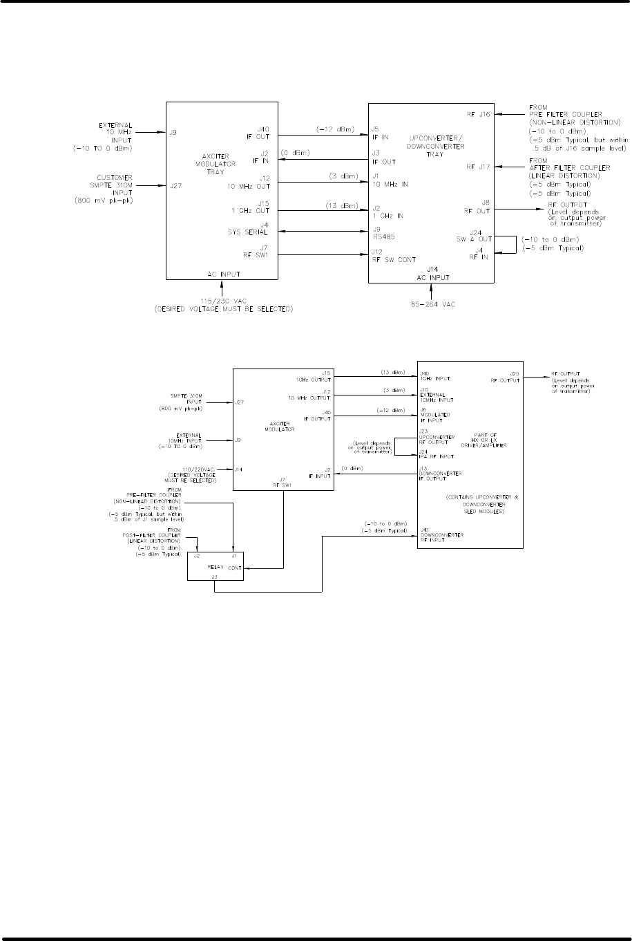
Figure 2- 2: Block Diagram Axciter tray-based system
Figure 2-3: Block Diagram Axciter sled-based system
1. Using the supplied cables and any other cables needed, make the
necessary interconnections between the Axciter modulator tray and the
upconverter/downconverter tray, in a tray-based system or the
driver/amplifier chassis assembly, in a sled-based system. Refer to
Figures 2-4, 2-5 & 2-6, the information in Tables 2-1, 2-2, 2-3 & 2-4
and the preceding block diagrams to aide in the reconnection of the
system.
2. The required external interconnections are detailed in Table 2-3.
Connect the SMPTE 310M signal source to the J27 or J23 input as
selected on the front panel of the Axciter modulator tray. This
connection applies to both the tray-based and sled-based systems
3. Connect the RF output of the upconverter/downconverter tray at J8 to
the driver or IPA of the transmitter, in a tray-based system. In a sled-
based system, connect the RF output of the driver/amplifier chassis
assembly at J25 to the driver or IPA of the transmitter
Digital ATSC Exciter-Modulator System Chapter 2,
Installation and Operating Instructions
Axcera Axciter, Rev. 0 7
4. There is a SPDT RF relay, mounted in the upconverter/ downconverter
tray, in a tray-based system or externally in a sled-based system,
which selects an RF sample from one of two places. The samples are
from either before the transmitter output channel mask filter, Non-
Linear Distortion, or after it, Linear Distortion. These samples are used
in the adaptive equalization process. Connect one 50O coax cable from
the directional coupler installed before the channel mask filter to the
normally open position of the RF relay at J17 on the rear of the
upconverter tray or to J1 on the external relay. Connect another 50O
coax cable from the directional coupler installed after the channel filter
to the normally closed input on the RF relay at J16 on the rear of the
upconverter tray or to J2 on the external relay. In a tray-based
system, connect a 50O coaxial jumper cable from the common
connection of the relay at J24 to the sample RF input jack at J4 on the
rear of the upconverter tray. In a sled-based system, connect a 50O
coaxial jumper cable from the common connection of the external relay
at J3 to the downconverter sample RF input jack at J41 on the rear of
the driver/amplifier assembly. The relay, mounted in the upconverter
or external, will select between the two samples under software control
from the Axciter Modulator tray.
5. Optional connections. There are several optional connections, detailed
in table 2-4. An external 10 MHz reference input can connect to J9.
An active loop-thru (that is, regenerated and reclocked) SMPTE 310
signal is available at the SMPTE 310 output located on the rear panel.
6. Ethernet connection. J1 on the rear of the Axciter modulator provides
an Ethernet connection that is used for troubleshooting.
Axciter Modulator, Upconverter/Downconverter & Driver/Amplifier Rear Panels
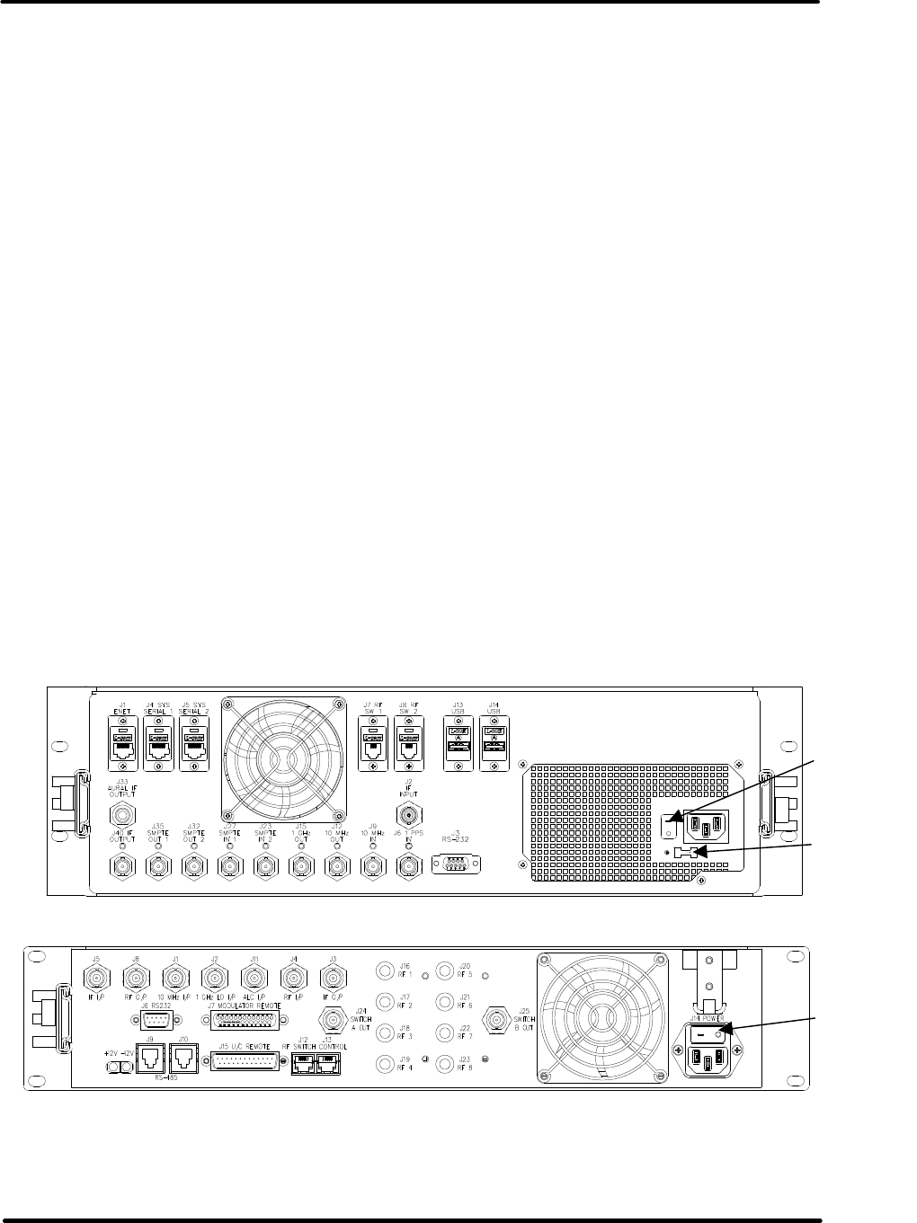
Figure 2-4: Axciter Modulator Tray, Rear View
Figure 2-5: Upconverter/Downconverter Tray, Rear View
115/230
Select
Switch
On/Off
Circuit
Breaker
On/Off
Circuit
Breaker
Digital ATSC Exciter-Modulator System Chapter 2,
Installation and Operating Instructions
Axcera Axciter, Rev. 0 8
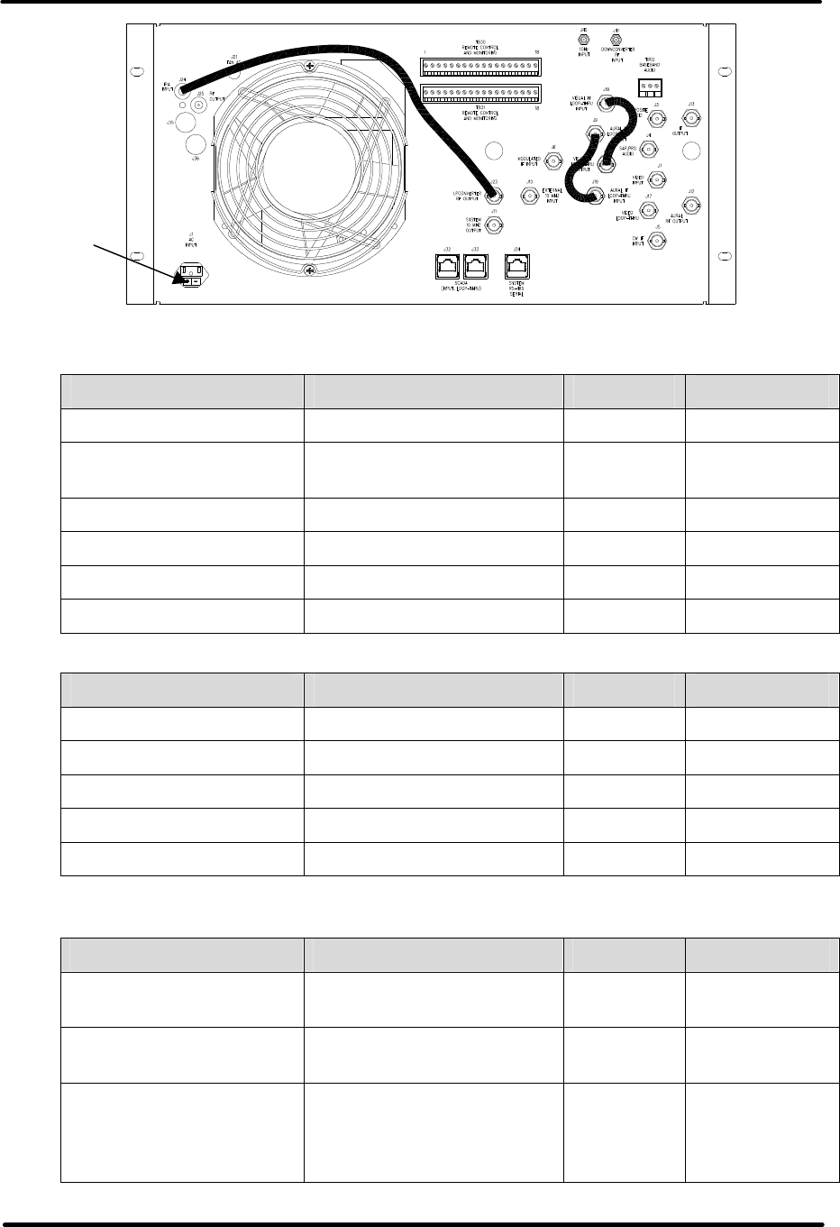
Figure 2-6: HX or LX Driver/Amplifier Chassis Assembly, Rear View
Table 2-1. Interconnections between modulator and upconverter (Tray Based System)
MODULATOR TRAY UPCONVERTER TRAY LEVEL CONNECTOR
(J2) IF input (J3) IF output 0 dBm 50Ω BNC
(J4) RS-485 serial 1
data (J9) RS-485 serial data N/A RJ-45
(J7) RF SW1 output (J12) RF SW CONT input N/A RJ-12
(J12) 10 MHz output (J1) 10 MHz input 3 dBm 50Ω BNC
(J15) 1GHz output (J2) 1GHz LO input 13 dBm 50Ω BNC
(J40) IF output (J5) IF input -12 dBm 50Ω BNC
Table 2-2. Interconnections between modulator and driver/amplifier (Sled Based System)
MODULATOR TRAY DRIVER/AMPLIFIER LEVEL CONNECTOR
(J2) IF input (J13) IF output 0 dBm 50Ω BNC
(J7) RF SW1 output N/A RJ-12
(J12) 10 MHz output (J10) 10 MHz input 3 dBm 50Ω BNC
(J15) 1GHz output (J40) 1GHz LO input 13 dBm 50Ω BNC
(J40) IF output (J6) Modulated IF input -12 dBm 50Ω BNC
Table 2-3. Connections between modulator, upconverter, and external equipment
(Tray Based System)
MODULATOR TRAY UPCONVERTER TRAY LEVEL CONNECTOR
(J27) SMPTE 310 input
#1 N/A 75Ω BNC
(J4) RF input (Normally
jumpered to J24) -5 dBm
Typical 50Ω BNC
(J8) RF output Level depends
on transmitter
output power
50Ω BNC
On/Off
Circuit
Breaker
Digital ATSC Exciter-Modulator System Chapter 2,
Installation and Operating Instructions
Axcera Axciter, Rev. 0 9
MODULATOR TRAY UPCONVERTER TRAY LEVEL CONNECTOR
(J16) Post-Filter sample
input (Linear Distortion)
-10 to 0 dBm
(-5 dBm
Typical) 50Ω BNC
(J17) Pre-Filter sample
input
(Non-Linear Distortion)
-10 to 0 dBm
(-5 dBm
Typical but
within .5 dB
of J6 sample
level)
50Ω BNC
(J24) SW A output
(Normally jumpered to J4) N/A 50Ω BNC
Table 2-4. Optional Connections to Axciter Modulator (Tray or Sled Based System)
MODULATOR NOTES
(J1) Ethernet input RJ-45 connector
(J3) RS-232 input DE-9 connector
(J5) RS-485 serial 2 data RJ-45 connector
(J6) 1 PPS external reference input 50Ω or 1kΩ BNC connection
selectable on screen
(J13 & J14) USB inputs USB connectors
(J8) RF SW 2 input RJ-12 connector
(J9) 10 MHz external reference input 50Ω BNC connection
(J23) SMPTE 310 input #2 75Ω BNC connection
(J33) Aural IF output 50Ω BNC connection
(J35) SMPTE 310 Serial #1 active output 75Ω BNC connection
(J32) SMPTE 310 Serial #2 active output 75Ω BNC connection
Power Supply Voltage
The power supply mounted in the Axciter modulator tray is capable of
operating using either 115 or 230 volts, by moving a switch, located below the
AC input jack located on the rear of the tray. The power supplies used in the
Axciter upconverter/downconverter tray, in the tray based system, is of a type
that requires no switching or jumper selection for operation from 115 or 320
volts. The power supply will operate correctly with any voltage from 85-264
volts AC, 47-440 Hz.
Note: There is an on/off circuit breaker located on the rear of the Axciter
modulator tray, the upconverter/downconverter tray and the driver/amplifier
chassis assembly, near the AC input plug. If the trays do not power up, check
that the on/off circuit breakers are on.
This completes the installation procedure for the Axciter tray-based and sled-
based systems.

Digital ATSC Exciter-Modulator System Chapter 2,
Installation and Operating Instructions
Axcera Axciter, Rev. 0 10
Setup and Operation Procedures
The initial setup and operation of the ATSC modulator should be performed
after the unit has been connected to an external SMPTE 310M source and the
Axciter modulator has been connected to the upconverter or to the
driver/amplifier chassis. Also check that the output of the upconverter or the
driver/amplifier is connected to the transmitter and that the pre-filter and
post-filter sample inputs from the transmitter are connected to the
upconverter or the reay as detailed in Tables 2-1, 2-2, 2-3, & 2-4. A detailed
description of the operational modes, menus, and setup of the Axciter
modulator can be found in rest of Chapter 2 of this manual. A description of
the upconverter/ downconverter tray and sled-based upconverter and
downconverter modules can be found in Chapter 3.
Modulator Operational Overview
The Axciter 8-VSB modulator accepts an ASTC transport stream in SMPTE
310MfFormat input and outputs an 8-VSB IF signal centered at 44 MHz.
The 44 MHz IF signal is upconverted to the desired channel by the upconverter
located in the upconverter tray or, in a sled-based system, as an upconverter
sled mounted in the driver/amplifier chassis assembly.
The signal generation function of the Axciter is also referred to as the “forward
signal path” in this manual. There is also a “reverse signal path” that is used
for automatic adaptive equalization.
Two transmitter output samples are taken from directional couplers located
before and after the channel mask filter and are applied to the upconverter
tray or the external Relay. The upconverter tray also contains a
downconverter that converts the RF sample to an IF output. In a sled-based
system, the downconverter sled is mounted in the driver/amplifier chassis
assembly.
The downconverted IF transmitter sample is digitized by the Axciter
modulator. It is then demodulated in non-real time software. The result is
analyzed to calculate linear and nonlinear adaptive equalizers to improve the
transmitted signal quality by compensating for the nonlinear compression of
the power amplifier, and the linear distortions (mostly group delay effects) of
the channel filter.
When a linear adaptive equalizer is being calculated, the transmitter sample is
taken after the channel mask filter so that its linear distortions can be “seen.”
When a nonlinear adaptive equalizer is being calculated, the transmitter
sample is taken before the channel mask filter, so that the distortion
sidebands being generated by the power amplifier can be seen (the channel
filter would remove the out-of-band sidebands).
The Axciter modulator contains a standard Personal Computer. The PC
performs user interface functions and the numerical processing necessary for
the adaptive linear and nonlinear equalization. The PC is not in the forward
signal path; if it fails the exciter will continue to generate a signal with the
most recently calculated equalization.

Digital ATSC Exciter-Modulator System Chapter 2,
Installation and Operating Instructions
Axcera Axciter, Rev. 0 11
SMPTE 310 Connection
The SMPTE 310 input receives a serial ATSC bitstream at a data rate of
19.392658 megabits per second. Line code is biphase mark. Signal amplitude
should be 800 millivolts peak to peak when terminated in a 75 ohm load.
The SMPTE 310 signal is internally regenerated and reclocked by the Axciter
modulator, and is available for testing or other uses at the connectors on the
rear panel.
IF Output Connection
The IF output is available on the rear connector labeled IF OUT. A sample of
the IF can be made available on the front panel. This sample should only be
used for test purposes and not for the primary IF output.
10 MHz Reference Connection
The modulator allows for the use of a 10 MHz external reference. If precise
frequency control is required, an external 10 MHz reference from a highly
stable source (such as a rubidium standard or GPS) may be applied to the
Axciter. With the external 10 MHz present, the internal 10 MHz OCXO is phase
locked to the high accuracy external reference.
1 PPS Reference Connection
Used for Single Frequency Network applications only.
Rear Panel LEDs
The rear panel of the modulator has an LED next to each coaxial connector.
During operation, a green LED next to the connector means that the signal is
present. A red LED means that the signal is absent or in a fault condition. A
dark LED means that the signal is not being used.
Graphical User Interface
The front panel of the modulator includes a color LCD that shows a wide range
of information about the operation of the Axciter modulator and the
upconverter. Details in the next section.
User Interface
This section describes the user interface, which is implemented as a graphical
set of screens following a menu structure. These screens are displayed on the
LCD screen on the front panel of the Axciter.
Topics include:
§ Navigating the user interface
§ Screen Displays and Details
§ User Interface Conventions
Navigating the User Interface
Each screen can contain a number of soft buttons, fields, graphs, and values.
The soft buttons along the right side of the screen display the function of the
corresponding adjacent front panel buttons. (NOTE: It is not a touch screen).
The primary function for these soft buttons is navigation between screens.
Digital ATSC Exciter-Modulator System Chapter 2,
Installation and Operating Instructions
Axcera Axciter, Rev. 0 12
The Color of values and fields indicate status. Graphs are used to display
DTVision analysis.
The top level menu structure has 5 options:
1. Control/Status
2. DTVision Linear (if installed)
3. DTVision Nonlinear (if installed)
4. Upconverter
5. Setup
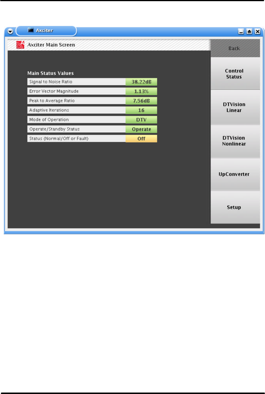
Example of screen is shown below.
Screens for Control/Status
Access the Control/Status screens by pressing the top soft button from the
main screen. Control/Status screens are listed in Table 2-4.
Table 2-4. Screens for Control/Status
SCREEN DESCRIPTION
Control/Status Provides a navigation home point for the
control/status.
Signals See page 14 for more information.
Power/Clocks See page 14 for more information.
Axact Equalizers See page 16 for more information.
LEDs See page 19 for more information.
History See page 21 for more information.
Digital ATSC Exciter-Modulator System Chapter 2,
Installation and Operating Instructions
Axcera Axciter, Rev. 0 13
Screens for DTVision Linear
Access the DTVision Linear screens by pressing the second soft button on the
Main Status screen. DTVision Linear screens are listed in Table 2-5.
Table 2-5. ATSC Screens
SCREEN DESCRIPTION
DTVision Linear
Home
(Spectrum) See page 22 for more information.
DTVision Const See page 24 for more information.
DTVision Eye See page 25 for more information.
DTVision Linear
Equalizer See page 26 for more information.
DTVision Linear
Quad See page 27 for more information.
Screens for DTVision Non-Linear
Access the DTVision Linear screens by pressing the second soft button on the
Main Status screen. DTVision Linear screens are listed in Table 2-5.
Table 2-5. ATSC Screens
SCREEN DESCRIPTION
DTVision Non-
Linear Home
(Spectrum) See page 29 for more information.
DTVision Peak
Avg See page 30 for more information.
DTVision Phase
Amp See page 31 for more information.
DTVision Non-
Linear Equalizer See page 32 for more information.
DTVision Non-
Linear Quad See page 33 for more information.
User Interface Conventions
Screens consist of fields, graphs, values and buttons. Fields provide either
status information and values or allow the user to change the values. The
graphs provide a visual display of the system status and allow analysis. The
colored value fields provide status information at a glance.
Soft buttons on the right side of the screen allow navigation. Each soft button
corresponds to a menu item on the screen. The Home button will take the
user back to the Main Status Screen. The Back button will take the user back
to the last screen they were on.
To change values, users must use the keypad to the right of the soft buttons.
Digital ATSC Exciter-Modulator System Chapter 2,
Installation and Operating Instructions
Axcera Axciter, Rev. 0 14
Fields
Buttons on the Screen
Buttons on the Front Panel
Home When Home is pressed, you are taken back to the home screen.
Back Back is used to return to the previous screen.
Help When the help button is pressed, the help screen relevant to
the screen you were on at the time you pressed ‘Help’ is
presented.
Show/hide
menu Pressing the show/hide menu button toggles the display of the
5 navigation buttons on the right side of the screen.
Soft Buttons
1-5
These 5 buttons perform the functions or navigation described
by the corresponding graphics adjacent to the buttons on the
right edge of the LCD screen.
Keypad The numeric keypad is used for entering values in the control
screen fields.
Keyboard Control:
A USB keyboard attached to the front panel will allow a user familiar with
Linux to login into
a console and check the status of the Axciter.
Special Keyboard Functions:
§ Home: takes user to the root screen, General Status Screen.
§ Back: ends the help screen and takes user back to previous screen.
Table 2-6. Key Map
KEY FRONT PANEL BUTTON
Alt F2 GUI interface
Alt F6 Linux Console
F1 Help
Other Interface Options
The user interface supports operation via the front panel mouse.
Digital ATSC Exciter-Modulator System Chapter 2,
Installation and Operating Instructions
Axcera Axciter, Rev. 0 15
Screen Displays and Details
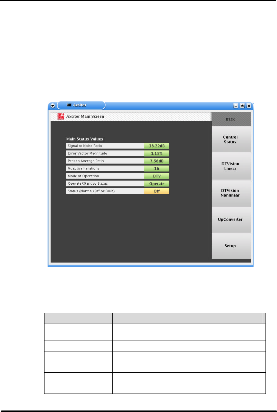
Axciter Main Screen
The purpose of this display is to show the general status of the Axciter.
Legend
Green: The green value indicates that there are no errors and everything is
normal and present.
Red: The red value indicates there are errors or problems.
Yellow: The yellow indicates the associated value is absent or not on or is at a
warning level.
Status
Signal to Noise Ratio: The Signal to Noise ratio expressed in decibels.
Error Vector Magnitude: The error vector magnitude expressed in %.
Peak to Average Ratio: The peak to average ratio of the transmitter output.
Adaptive Iterations: The number of adaptive iterations completed.
Mode of Operation: DTV, NTSC, or signal frequency network slave operation.
Digital ATSC Exciter-Modulator System Chapter 2,
Installation and Operating Instructions
Axcera Axciter, Rev. 0 16
Operate/Standby: States whether the Axciter is in standby or operate. This
is controlled by a system controller if there is one.
Status: Summary fault status of the exciter. See Control/Status page for
more details.
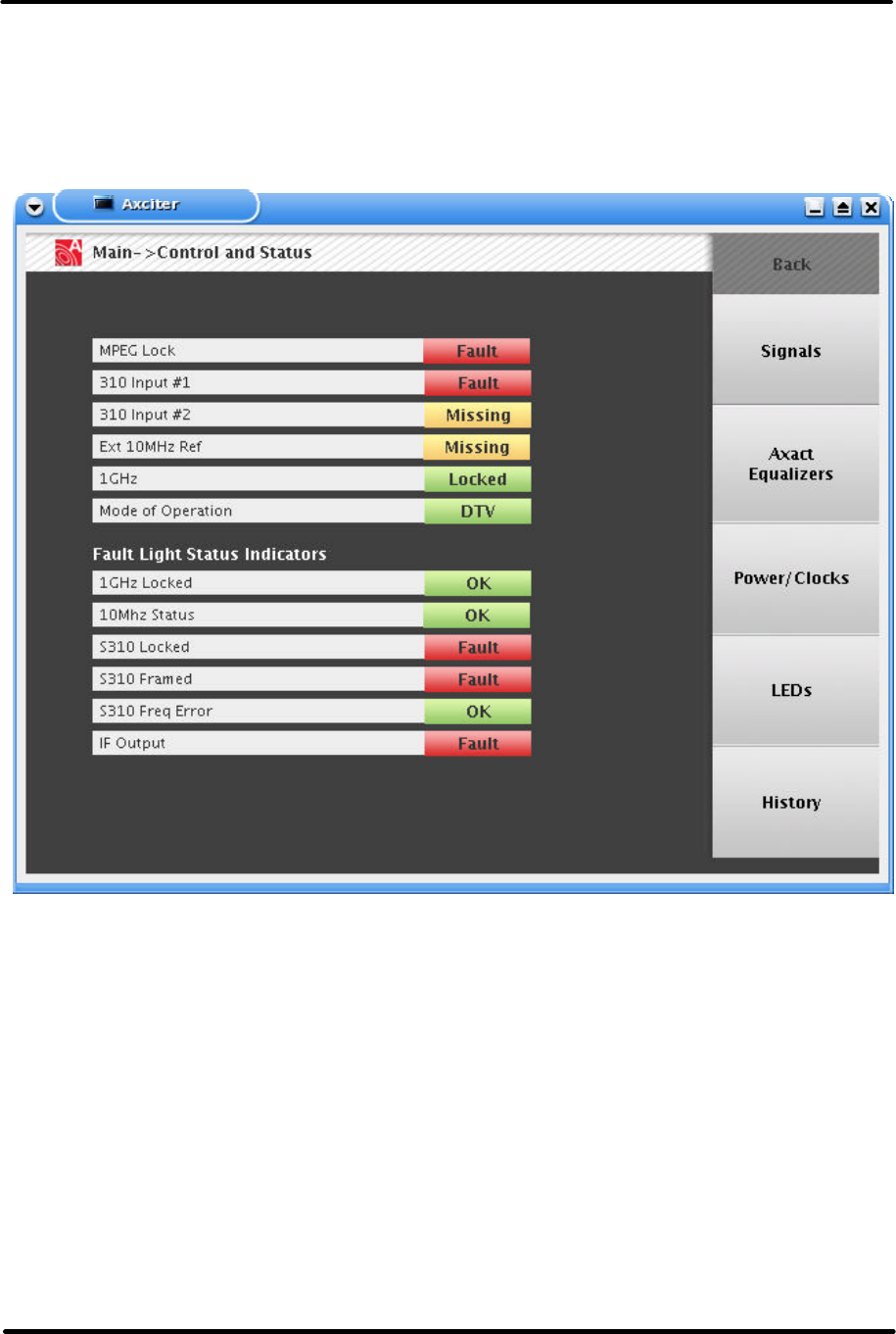
Control and Status Screen
The purpose of this display is to show the general status of the Axciter.
Status
SMPTE Lock: Indicates whether the SMPTE sync packets are detected.
SMPTE 310 Input #1: The SMPTE 310 (ATSC) input signal is present.
SMPTE 310 Input #2: The SMPTE 310 (ATSC) input signal is present.
10 MHz Ref In: The externally applied 10 MHz reference signal is present.
IF In: The downconverted IF sample of the transmitter's output is present.
IF Out: The exciter is producing an IF output signal.
Digital ATSC Exciter-Modulator System Chapter 2,
Installation and Operating Instructions
Axcera Axciter, Rev. 0 17
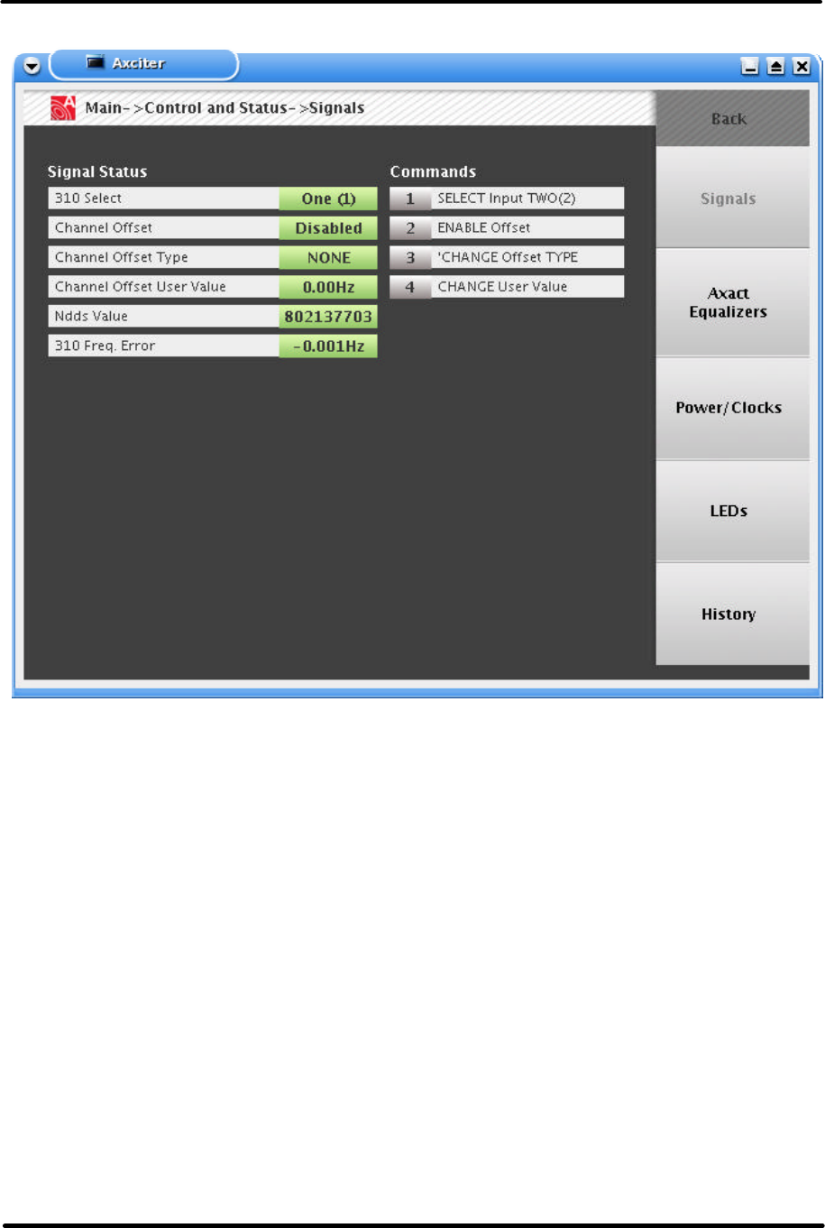
Signals Status Screen
Signals
+310 Select: Displays which 310 input is being used on air.
Channel Offset: Displays whether an offset is in use.
Channel Offset Type: Displays the type of offset selected.
Channel Offset User Value: The amount of manual offset selected.
NDDS Value: An internal raw reading used for 310 clocking.
310 Frequency Error: The calculated frequency error of the active 310 input.
Commands
1: Toggles between the two 310 inputs.
2: Enables or disables the selected offset.
3: Allows user to select preset, manual offsets, or no offsets.
4: Allows direct entry of manual offset amount.
Digital ATSC Exciter-Modulator System Chapter 2,
Installation and Operating Instructions
Axcera Axciter, Rev. 0 18
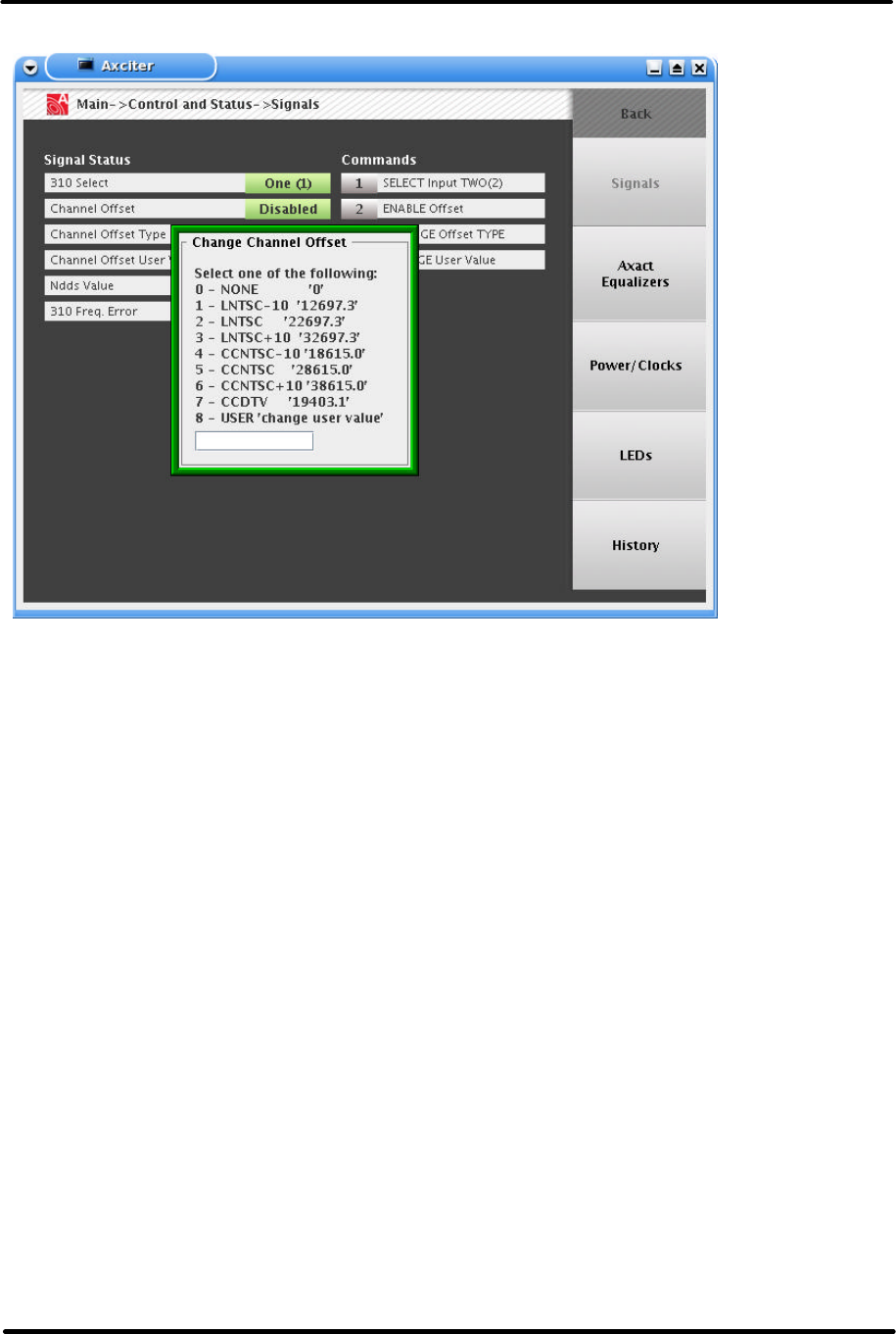
Channel Offset Example
CHANNEL OFFSET
Enable
Selecting this option will change the transmitted frequency by the selected
offset value. (Channel offsets are used to minimize co-channel or adjacent
channel interference.)
Disable
Selecting this option will set the transmitted frequency to the standard value
for the channel in use (pilot 309.440559 kHz above the lower channel edge.)
This display allows channel offset adjustment for the ATSC mode of the
Axciter.
Channel offsets are used to minimize interference between co-channel and/or
adjacent channel signals. Selection of a type of channel offset is dependent on
the kind of interference being caused or received. Check with the appropriate
regulatory body (FCC) and review your DTV channel assignment before
beginning transmission with a channel offset.
DTV/DTV
+19403.07Hz
-19403.07Hz
This offset frequency is chosen to minimize co-channel interference between
two DTV signals.
Digital ATSC Exciter-Modulator System Chapter 2,
Installation and Operating Instructions
Axcera Axciter, Rev. 0 19
Manual
If research into channel offsets produces new values that can mitigate certain
interference conditions, any channel offset value can be entered in the box.
None
Disables channel offset. Select this box to transmit without any channel
offset.
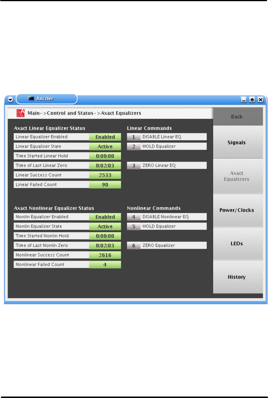
AXACT Equalizers

Digital ATSC Exciter-Modulator System Chapter 2,
Installation and Operating Instructions
Axcera Axciter, Rev. 0 20
LINEAR EQUALIZER
Hold
When this option is selected, the linear equalizer is forced to use the current
values rather than calculating new values. This will continue until the Hold
option is deselected. The equalizer will not adjust to compensate for changes
while this is selected.
Zero
When Zero is selected, the linear equalizer is loaded with unity values
describing a flat response and the demodulation routine is restarted. This
option will clear itself when finished.
Enable
This option turns on the adaptive linear equalizer. The linear equalizer corrects
for frequency response and group delay characteristics in the transmitter and
the channel filter.
Disable
This option disables the adaptive linear equalizer. Group delay and frequency
response characteristics will not be removed from the transmitted signal.
Linear Successes
This value shows the number of times since Axact started that Linear Adaptive
was successful.
Linear Failures
This value shows the number of times since Axact started that Linear Adaptive
was unable to use the data available to fix the equalizer.
NONLINEAR EQUALIZER
Hold
When this option is selected, the nonlinear equalizer is forced to use the
current values rather than calculating new values. This will continue until the
Hold option is deselected. The equalizer will not adjust to compensate for
changes while this is selected.
Zero
When Zero is selected, the nonlinear equalizer is loaded with unity values with
no pre-correction and the demodulation routine is restarted. This option will
clear itself when finished.
Enable
This option enables the adaptive nonlinear equalizer. The nonlinear equalizer
corrects for nonlinear distortions, such as gain compression and incidental
phase modulation, in the transmitter's power amplifier.
Disable
This option disables the adaptive nonlinear equalizer. Any nonlinear distortion
added to the signal by the power amplifier will not be corrected.
Nonlinear Success
This value shows the number of times Nonlinear Adaptive was successful.
Digital ATSC Exciter-Modulator System Chapter 2,
Installation and Operating Instructions
Axcera Axciter, Rev. 0 21
Nonlinear Failures
This value shows the number of times since Axact started that Nonlinear
Adaptive was unable to use the data available to fix the equalizer.
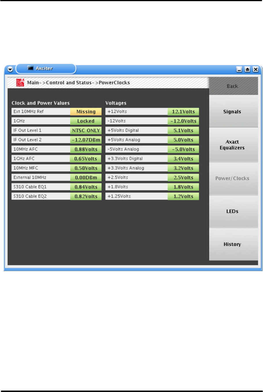
Clock and Power Status Screen
Clock Power
10MHz: External reference presence indication.
1GHz: Lock status of internal 1GHz clock oscillator.
IF Out Level 1: Level of 12VDC source.
IF Out Level 2: Level of 12VDC source.
Supplies (Power)
+12V Supply: Voltage of regulated +12VDC source.
Digital ATSC Exciter-Modulator System Chapter 2,
Installation and Operating Instructions
Axcera Axciter, Rev. 0 22
-12V Supply: Voltage of regulated -12VDC source.
+5V Supply: Voltage of regulated +5V source.
Coder +3.3V: Channel Coder's 3.3V voltage regulator output.
Mod +3.3V: Modulator board's 3.3V voltage regulator output.
IF +3.3V: IF board's 3.3V voltage regulator output.
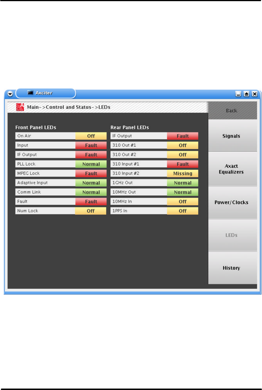
LED Status Screen
LED Status Screen gives a user a view of the LEDs both on the front of the Axciter as well as
the rear. This screen mainly intended for remote viewers.

Digital ATSC Exciter-Modulator System Chapter 2,
Installation and Operating Instructions
Axcera Axciter, Rev. 0 23
Front Panel LEDs
LED
FUNCTION
Power
On Air
Input
IF Output
PLL Lock
SMPTE Lock
Adaptive Input
Communication Link
Fault
Number Lock
Indicates the keypad
types numbers only, arrows do not work.
Rear Panel LEDs
The rear panel of the modulator has an LED next to each coaxial connector. During
operation, a green LED next to the connector means that the signal is present. A red LED
means that the signal is absent or in a fault condition. A dark LED indicates that the signal is
not being used
LED
TITLE
FUNCTION
J40
IF OUTPUT
J35
310 OUTPUT #1
J32
310 OUTPUT #2
J27
310 INPUT #1
J23
310 INPUT #2
J15
1 GHz OUT
J12
10 MHz OUT
J9
10 MHz IN
J6
1
PPS IN
Digital ATSC Exciter-Modulator System Chapter 2,
Installation and Operating Instructions
Axcera Axciter, Rev. 0 24
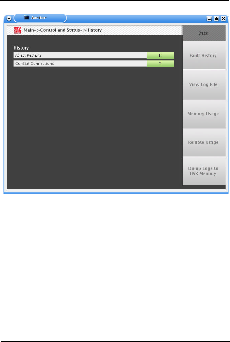
History
Axact Restarts
This value lists the number of times the AXACT sub-program has restarted.
This may indicate a problem with communications and/or hardware.
ConStat Connections
This value lists the number of times the ConStat server has reconnected to
the Netburner computer. This may indicate a problem with communications
and/or the Netburner itself. This number may not represent the number of
times the Netburner has reset itself, just that the server had to reconnect.

Digital ATSC Exciter-Modulator System Chapter 2,
Installation and Operating Instructions
Axcera Axciter, Rev. 0 25
DTVision Linear - Optional
This section contains information regarding the DTVision Screens. These screens are
optional diagnostic screens. They are not necessary for the operation of the Axciter.
However, they greatly enhance the experience. These graphs provide the same type of
views as an EFA.
All of the Linear Screens have the following reference values on the bottom of the screens.
dB Stretch
This value is the maximum amount of gain boost being generated by the
Nonlinear Equalizer. This value is approximately equal to the maximum
amount of gain compression of the power amplifier.
dB Compression
This value is the minimum amount of gain being generated by the Nonlinear
Equalizer. This value is indicative of any relative "stretch" being produced in
the power amplifier.
Phase Shift
This is the maximum value of instantaneous phase shift being produced by the
Nonlinear Equalizer. This value corresponds to the incidental phase
modulation of the power amplifier.
dB Boost
This is the maximum amount of amplitude boost being produced by the Linear
Equalizer. This value corresponds to the lowest point in the channel frequency
response.
dB Attenuation
This is the minimum gain level being produced by the Linear Equalizer. This
value corresponds to the highest point in the channel frequency response.
ns Equalizer Delay
This is the maximum group delay variation in nanoseconds of the Linear
Equalizer.
EVM The error vector magnitude (EVM) value indicates quality of the digital
modulation. EVM is defined as the RMS error at the sampling instants divided
by the RMS of the ideal symbols. The error is expressed as a percentage. As
signal quality increases, this value decreases.
S/N The transmitted signal quality is also expressed as an in-band signal to noise
ratio, expressed in dB. As signal quality increases, this value will increase
(logarithmically).
DAC Headroom
This parameter shows the amplitude (in dB) of the equalized IF signal with
respect to the maximum output from the digital to analog converter (DAC). A
positive value indicates normal operation and no clipping. If this value is ever
negative, then there is clipping in the IF modulator, nonlinear equalizer,
Digital ATSC Exciter-Modulator System Chapter 2,
Installation and Operating Instructions
Axcera Axciter, Rev. 0 26
and/or the DAC. If this happens, lower the unity gain reference point for the
nonlinear equalizer.
Peak to Average Ratio
This value shows the peak to average ratio of the transmitted signal. This
value is typically 6 to 8 dB for a perfect signal. A value significantly lower will
indicate peak compression. A small amount of peak compression is normal.
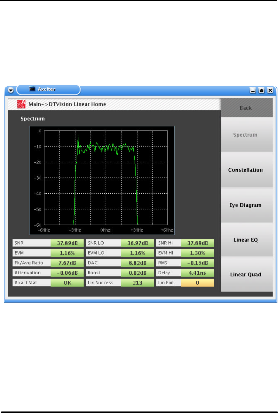
DTVision Linear Home/ Spectrum Screen
8-VSB Spectrum Display
The spectrum display shows the energy of the output signal as a function of
frequency. An ideal 8VSB signal will occupy 6 MHz of bandwidth. Power
amplifier nonlinearity will cause undesired "shoulders" to appear on each side
of the spectrum.
Digital ATSC Exciter-Modulator System Chapter 2,
Installation and Operating Instructions
Axcera Axciter, Rev. 0 27
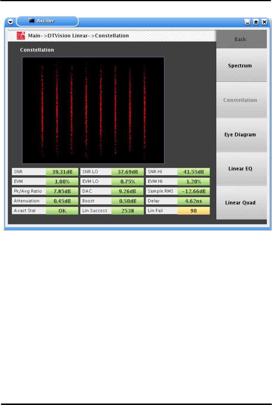
DTVision Constellation Screen
I & Q Constellation Display
This display is created by plotting the 8-VSB in-phase (I) component against
the quadrature (Q) component. When the samples are taken at the symbol
time, then the data points will be precisely aligned along the eight vertical
lines. Those eight vertical lines are the eight VSB data levels.