UBS Axcera LU6000AL 6000-Watt UHF Translator User Manual TITLE PAGE
UBS-Axcera 6000-Watt UHF Translator TITLE PAGE
Contents
- 1. Compiled Driver Manual
- 2. Compiled External Amplifier Manual
Compiled External Amplifier Manual

INSTRUCTION MANUAL
Innovator
LX Series
Analog Power Amplifier
Assembly
AXCERA, LLC
103 FREEDOM DRIVE P.O. BOX 525 LAWRENCE, PA 15055-0525 USA
(724) 873-8100 • FAX (724) 873-8105
www.axcera.com • info@axcera.com

LX Series Power Amplifier Assembly Table of Contents
LX Series, Rev. 1 March 2, 2005 i
TABLE OF CONTENTS
CHAPTER 1 INTRODUCTION
SECTION PAGE
1.1 Manual Overview ............................................................................ 1-1
1.2 Assembly Designation Numbers ......................................................... 1-1
1.3 Safety........................................................................................... 1-2
1.4 Contact Information.....................................................................1-2
1.5 Material Return Procedure................................................................. 1-2
1.6 Limited One Year Warranty for Axcera Products..................................... 1-3
CHAPTER 2 AMPLIFIER ASSEMBLY DESCRIPTION, MAINTENANCE
& REMOTE CONTROL CONNECTIONS
2.1 LX Series Power Amplifier Chassis Assembly Overview........................... 2-1
2.1.1 Power Amplifier Chassis Configurations ....................................... 2-3
2.1.1.1 250 Watt Power Amplifier Chassis Configuration................... 2-3
2.1.1.2 500 Watt Power Amplifier Chassis Configuration................... 2-3
2.1.1.3 1 kW Power Amplifier Chassis Configuration ........................ 2-3
2.1.2 System Configurations............................................................. 2-3
2.1.2.1 250W, 500W or 1kW System Configurations........................ 2-4
2.1.2.2 2 kW System Configuration.............................................. 2-4
2.1.2.3 3 kW System Configuration.............................................. 2-5
2.1.2.4 4 kW System Configuration.............................................. 2-5
2.1.2.5 5 kW System Configuration.............................................. 2-6
2.1.2.6 6 kW System Configuration.............................................. 2-6
2.1.3 Power Amplifier Module Assembly, 250W..................................... 2-8
2.1.4 Power Supply Module Assembly................................................2-10
2.1.5 Front Panel LCD Display Screens ..............................................2-10
2.2 System Operation ..........................................................................2-10
2.2.1 Principles of Operation............................................................2-10
2.3 Maintenance.................................................................................2-12
2.4 Customer Remote Connections ...................................................2-12
CHAPTER 3 SITE CONSIDERATIONS, INSTALLATION AND SETUP PROCEDURES
3.1 Site Considerations.......................................................................... 3-1
3.2 Unpacking the Chassis w/Modules, bandpass and trap filters.................... 3-5
3.3 Installing the Chassis w/Modules and filters.......................................... 3-5
3.4 AC Input ....................................................................................... 3-6
3.5 Setup and Operation........................................................................ 3-7
3.5.1 Input Connections .................................................................. 3-7
3.5.2 Initial Turn On ....................................................................... 3-9
3.5.2.1 Receiver Module LEDs on Front Panel................................. 3-9
3.5.2.2 Modulator Module LEDs on Front Panel............................... 3-9
3.5.2.3 IF Processor Module LEDs on Front Panel...........................3-10
3.5.2.4 Upconverter Module LEDs on Front Panel...........................3-10
3.5.2.5 Controller Module LEDs on Front Panel ..............................3-10
3.5.2.6 Power or Driver Amplifier Module LEDs on Front Panel..........3-10
3.5.3 Front Panel Screens for the (Optional) Exciter Switcher Tray ..........3-10
3.5.4 Front Panel Screens for the Exciter/Amplifier Chassis Assembly ......3-13
3.5.5 Operation Procedure ..............................................................3-22

LX Series Power Amplifier Assembly Table of Contents
LX Series, Rev. 1 March 2, 2005 ii
TABLE OF CONTENTS - (Continued)
SECTION PAGE
CHAPTER 4 CIRCUIT DESCRIPTIONS
4.1 Power Amplifier Module .................................................................... 4-1
4.1.1 UHF Phase/Gain Board............................................................. 4-1
4.1.2 150 Watt Driver Pallet Assembly................................................ 4-2
4.1.3 150 Watt Driver, Dual Output Board........................................... 4-2
4.1.4 UHF Module Assembly, RF Module Pallet, Philips ........................... 4-2
4.1.5 2 Way UHF Combiner Assembly................................................. 4-3
4.1.6 Amplifier Control Board............................................................ 4-3
4.2 Power Supply Assembly.................................................................... 4-5
CHAPTER 5 DETAILED ALIGNMENT PROCEDURES
5.1 Module Replacement........................................................................ 5-1
5.1.1 Initial Test Setup.................................................................... 5-1
5.2 Innovator LX Series Exciter/Driver Chassis Assembly.............................. 5-1
5.2.1 (Optional) Receiver Module Assembly ......................................... 5-2
5.2.2 Modulator Module Assembly...................................................... 5-2
5.2.3 IF Processor Module Assembly .................................................. 5-3
5.2.4 VHF/UHF Upconverter Module Assembly ...................................... 5-3
5.2.5 Setting up the Drive Level of the Transmitter............................... 5-4
5.2.6 Changing the Channel on the Transmitter.................................... 5-4
5.2.7 Frequency Response Delay Equalization Adjustment ...................... 5-4
5.2.8 Linearity Correction Adjustment ................................................ 5-5
5.3 Bandpass Filter Assembly ................................................................. 5-6
5.4 (Optional) One or Two Section Trap Filter Assembly ............................... 5-7
5.4.1 Fine Tuning ........................................................................... 5-8
5.4.2 Major Tuning ......................................................................... 5-8
5.5 Calibration of Transmitter Forward Output Power Level........................... 5-9
5.6 Calibration of Transmitter Reflected Output Power Level ........................5-10
APPENDICES
APPENDIX A INNOVATOR LX SERIES SPECIFICATIONS
APPENDIX B DRAWINGS AND PARTS LISTS
APPENDIX C TRANSMITTER LOG SHEET

LX Series Power Amplifier Assembly Table of Contents
LX Series, Rev. 1 iii
LIST OF FIGURES
FIGURE PAGE
1-1 Brady Marker Identification Drawing............................................. 1-1
2-1 1kW Power Amplifier Assembly Racking Plan .................................. 2-3
3-1 1 kW Minimum Ventilation Configuration ....................................... 3-4
3-2 Front and Rear View Exciter/Driver .............................................. 3-5
3-3 Front and Rear View 76” Cabinet Typical 4kW Configuration.............. 3-6
3-4 AC Input Box Assembly ............................................................. 3-6
3-5 Rear View of LX Series Transmitter/Translator................................ 3-8
4-1 250 Watt UHF Amplifier Module ................................................... 4-2
5-1 Typical Red Field Spectrum......................................................... 5-5
5-2 Bandpass Filter........................................................................ 5-7
5-3 One Section Trap Filter.............................................................. 5-8

LX Series Power Amplifier Assembly Table of Contents
LX Series, Rev. 1 iv
LIST OF TABLES
TABLE PAGE
2-1 Typical LX Series Analog System Drawings and Parts Lists................ 2-3
2-2 Typical LX Series Digital System Drawings and Parts Lists................. 2-4
2-3 LX Series Power Amplifier Chassis Assemblies ................................ 2-8
2-4 Power Amplifier Status Indicators ................................................ 2-9
2-5 Power Amplifier Control Adjustments............................................ 2-9
2-6 Power Amplifier Sample ............................................................. 2-9
2-7 LX Series Customer Remote Connections...............................2-13
3-1 LX Series Transmitters AC Input and Current Requirements.............. 3-1
3-2 LX Series Transmitters AC Input and Current Requirements.............. 3-6
3-3 Rear Chassis Connections for LX Series Transmitter......................... 3-8
(Optional) Exciter Switcher Menu Screens....................................................3-11
3-4 Exciter Switcher Menu 01 Splash Screen #1 .................................3-11
3-5 Menu 02 Splash Screen #2........................................................3-11
3-6 Menu 03 Exciter Switcher Control Screen, Automatic Operation.......3-11
3-7 Menu 04 Exciter Switcher Control Screen, Manual Operation...........3-11
3-8 Menu 05 Exciter Switcher Control Screen, Amps On Line................3-11
3-9 Menu 06 Exciter Switcher Control Screen, Cancel Auto Back up.......3-12
3-10 Menu 07 Exciter Switcher Control Screen, B Back up to A...............3-12
3-11 Menu 08 Exciter Switcher Control Screen, back up Changeover.......3-12
3-12 Menu 09 Exciter Switcher Control Screen, Ext Amp Status..............3-12
3-13 Menu 10 Exciter Switcher Control Screen, Ext Amp Status..............3-12
LX System Controller Menu Screens .............................................................3-13
3-14 Menu 01 Splash Screen #1........................................................3-13
3-15 Menu 02 Splash Screen #2........................................................3-13
3-16 Menu 10 Main Screen ..............................................................3-13
3-17 Menu 11 Error List Access Screen...............................................3-14
3-18 Menu 12 Transmitter Device Data Access Screen ..........................3-14
3-19 Menu 13 Transmitter Configuration Access Screen ........................3-14
3-20 Menu 20 Error List Display Screen..............................................3-14
3-21 Menu 30 Transmitter Device Details Screen .................................3-15
3-22 Menu 30-1 System Details Screens ............................................3-15
3-23 Transmitter Device Parameters Detail Screens .............................3-15
3-24 Menu 40 Authorized Personnel Screen ........................................3-16
3-25 Menu 40-1 Transmitter Set Up: Power Raise/Lower Screen.............3-17
3-26 Menu 40-2 Transmitter Set Up: Model Select Screen .....................3-17
3-27 Menu 40-3 Transmitter Set Up: Receiver Channel Configuration......3-18
3-28 Menu 40-4 Transmitter Set Up: Upconverter Channel Select Screen.3-18
3-29 Menu 40-5 Transmitter Set Up: Serial Address Screen...................3-18
3-30 Menu 40-6 Transmitter Set Up: Station ID Screen..........................3-18
3-31 Menu 40-7 Transmitter Set Up: System Visual Power Cal. Screen......3-19
3-32 Menu 40-8 Transmitter Set Up: System Aural Power Cal. Screen.......3-19
3-33 Menu 40-9 Transmitter Set Up: System Rfltd. Power Cal. Screen ......3-19
3-34 Menu 40-10 Transmitter Set Up: Modulated Output Cal. Screen........3-19
3-35 Menu 40-11 Transmitter Set Up: Aural Deviation Screen .................3-20
3-36 Menu 40-12 Transmitter Set Up: Fwrd Pwr Fault Threshold Screen....3-20
3-37 Menu 40-13 Transmitter Set Up: Refl Power Fault Threshold Screen ..3-20
3-38 Menu 40-14 Transmitter Set Up: DLC Control Screen......................3-20
3-39 Menu 40-15 Transmitter Set Up: Auto Standby Control Screen.........3-21

LX Series Power Amplifier Assembly Table of Contents
LX Series, Rev. 1 v
LIST OF TABLES
TABLE PAGE
3-40 Menu 40-16 Transmitter Set Up: Receiver ALC Fault Set Up Screen...3-21
3-41 Menu 40-17 Transmitter Set Up: Inner Loop Gain Control Screen......3-21
3-42 Menu 40-18 Transmitter Set Up: Optional System Control Screen .....3-21
3-43 Menu 40-19 Transmitter Set Up: Remote Command Control Screen...3-22
5-1 Typical Bandpass Values ............................................................ 5-6
5-2 Results of Tuning the Output Trap Filter........................................ 5-9

LX Series Power Amplifier Assembly Chapter 1, Introduction
LX Series, Rev. 1 1-1
Chapter 1
Introduction
1.1 Manual Overview
This manual explains the installation,
setup, alignment, and maintenance
procedures for the Power Amplifier
Assembly for the Innovator LX Series
transmitter. It is important that you
read all of the instructions, especially
the safety information in this chapter,
before you begin to install or operate
the unit.
This instruction manual is divided into
five chapters and supporting appendices.
Chapter 1, Introduction, contains
information on the assembly numbering
system used in the manual, safety,
maintenance, return procedures, and
warranties. Chapter 2, Amplifier
Assembly Description, Maintenance &
Remote Control Connections, describes
the amplifier assembly and includes
discussions on control and status
indicators and remote control
connections. Chapter 3, Site
Considerations, Installation and Setup
Procedures, explains how to unpack,
install, setup, and operate the power
amplifier assembly. Chapter 4, Circuit
Descriptions, contains circuit level
descriptions for boards and board level
components in the power amplifier.
Chapter 5, Detailed Alignment
Procedures, provides information on
adjusting the power amplifier and the
system for optimal operation. Appendix
A contains system specifications.
Appendix B contains assembly and
subassembly drawings and parts lists.
Appendix C contains a transmitter log
sheet.
1.2 Assembly Designators
Axcera has assigned assembly numbers,
such as Ax (x=1,2,3…), to all assemblies,
trays, and boards that are referenced in
the text of this manual and shown on the
block diagrams and interconnect
drawings provided in the appendices.
These supporting documents are
arranged in increasing numerical order in
the appendices. Section titles in the text
for assembly or tray descriptions or
alignment procedures contain the
associated part number(s) and the
relevant appendix that contains the
drawings for that item.
The cables that connect between the
boards within a tray or assembly and
that connect between the trays, racks
and cabinets are labeled using Brady
markers.
Figure 1-1 is an example of a Brady
marked cable. There may be as few as
two or as many as four Markers on any
one cable. These Brady markers are
read starting furthest from the
connector. If there are four Brady
Markers, this marker is the transmitter
number such as transmitter 1 or
transmitter 2. The next or the furthest
Brady Marker is the rack or cabinet
number on an interconnect cable or the
board number within a tray. The next
number on an interconnect cable is the
tray location or number. The Brady
marker closest to the connector is the
jack or connector number on an
interconnect cable or the jack or
connector number on the board within a
tray.
Figure 1-1 Brady Marker Identification Drawing

LX Series Power Amplifier Assembly Chapter 1, Introduction
LX Series, Rev. 1 1-2
1.3 Safety
The transmitters and associated power
amplifier assemblies manufactured by
Axcera are designed to be easy to use
and repair while providing protection
from electrical and mechanical hazards.
Listed throughout the manual are notes,
cautions, and warnings concerning
possible safety hazards that may be
encountered while operating or servicing
the transmitter. Please review these
warnings and familiarize yourself with the
operation and servicing procedures
before working on the assembly.
Read All Instructions – All of the
operating and safety instructions should
be read and understood before operating
this equipment.
Retain Manuals – The manuals for the
power amplifier assembly and the
transmitter should be retained at the
transmitter site for future reference. We
provide two sets of manuals for this
purpose; one set can be left at the office
while one set can be kept at the site.
Heed all Notes, Warnings, and
Cautions – All of the notes, warnings,
and cautions listed in this safety section
and throughout the manual must be
followed.
Follow Instructions – All of the
operating and use instructions for the
amplifier assembly should be followed.
Cleaning – Unplug or otherwise
disconnect all power from the equipment
before cleaning. Do not use liquid or
aerosol cleaners. Use a damp cloth for
cleaning.
Ventilation – Openings in the cabinets
and modules front panels are provided
for ventilation. To ensure the reliable
operation of the amplifier assembly, and
to protect the unit from overheating,
these openings must not be blocked.
Servicing – Do not attempt to service
this product yourself until becoming
familiar with the equipment. If in doubt,
refer all servicing questions to qualified
Axcera service personnel.
Replacement Parts – When
replacement parts are used, be sure that
the parts have the same functional and
performance characteristics as the
original part. Unauthorized substitutions
may result in fire, electric shock, or other
hazards. Please contact the Axcera
Technical Service Department if you have
any questions regarding service or
replacement parts.
1.4 Contact Information
The Axcera Field Service Department can
be contacted by phone at (724) 873-
8100 or by fax at (724) 873-8105.
Before calling Axcera, please be prepared
to supply the Axcera technician with
answers to the following questions. This
will save time and help ensure the most
direct resolution to the problem.
1. What are the Customers’ Name
and call letters?
2. What are the model number and
type of transmitter?
3. Is the transmitter digital or
analog?
4. How long has the transmitter
been on the air? (Approximately
when was the transmitter
installed.)
5. What are the symptoms being
exhibited by the transmitter?
Include the current control/power
supply LCD readings and the
status of LEDs on the front
panels of the modules. If
possible, include the
control/power supply LCD
readings before the problem
occurred.
1.5 Return Material Procedure
To insure the efficient handling of
equipment or components that have been
returned for repair, Axcera requests that
each returned item be accompanied by a

LX Series Power Amplifier Assembly Chapter 1, Introduction
LX Series, Rev. 1 1-3
Return Material Authorization Number
(RMA#).
An RMA# can be obtained from any
Axcera Field Service Engineer by
contacting the Axcera Field Service
Department at (724) 873-8100 or by fax
at (724) 873-8105. This procedure
applies to all items sent to the Field
Service Department regardless of
whether the item was originally
manufactured by Axcera.
When equipment is sent to the field on
loan, an RMA# is included with the unit.
The RMA# is intended to be used when
the unit is returned to Axcera. In
addition, all shipping material should be
retained for the return of the unit to
Axcera.
Replacement assemblies are also sent
with an RMA# to allow for the proper
routing of the exchanged hardware.
Failure to close out this type of RMA# will
normally result in the customer being
invoiced for the value of the loaner item
or the exchange assembly.
When shipping an item to Axcera, please
include the RMA# on the packing list and
on the shipping container. The packing
slip should also include contact
information and a brief description of why
the unit is being returned.
Please forward all RMA items to:
AXCERA, LLC
103 Freedom Drive
P.O. Box 525
Lawrence, PA 15055-0525 USA
For more information concerning this
procedure, call the Axcera Field Service
Department.
Axcera can also be contacted through e-
mail at info@axcera.com and on the
Web at www.axcera.com.
1.6 Limited One Year Warranty for
Axcera Products
Axcera warrants each new product that
it has manufactured and sold against
defects in material and workmanship
under normal use and service for a
period of one (1) year from the date of
shipment from Axcera's plant, when
operated in accordance with Axcera's
operating instructions. This warranty
shall not apply to tubes, fuses,
batteries, or bulbs.
Warranties are valid only when and if
(a) Axcera receives prompt written
notice of breach within the period of
warranty, (b) the defective product is
properly packed and returned by the
buyer (transportation and insurance
prepaid), and (c) Axcera determines, in
its sole judgment, that the product is
defective and not subject to any misuse,
neglect, improper installation,
negligence, accident, or (unless
authorized in writing by Axcera) repair
or alteration. Axcera's exclusive liability
for any personal and/or property
damage (including direct, consequential,
or incidental) caused by the breach of
any or all warranties, shall be limited to
the following: (a) repairing or replacing
(in Axcera's sole discretion) any
defective parts free of charge (F.O.B.
Axcera’s plant) and/or (b) crediting (in
Axcera's sole discretion) all or a portion
of the purchase price to the buyer.
Equipment furnished by Axcera, but not
bearing its trade name, shall bear no
warranties other than the special hours-
of-use or other warranties extended by
or enforceable against the manufacturer
at the time of delivery to the buyer.
NO WARRANTIES, WHETHER
STATUTORY, EXPRESSED, OR
IMPLIED, AND NO WARRANTIES OF
MERCHANTABILITY, FITNESS FOR
ANY PARTICULAR PURPOSE, OR
FREEDOM FROM INFRINGEMENT,
OR THE LIKE, OTHER THAN AS
SPECIFIED IN PATENT LIABILITY
ARTICLES, AND IN THIS ARTICLE,
SHALL APPLY TO THE EQUIPMENT
FURNISHED HEREUNDER.

LX Series Power Amplifier Assembly Chapter 1, Introduction
LX Series, Rev. 1 1-4
F WARNING!!!
× HIGH VOLTAGE Ø
DO NOT ATTEMPT TO REPAIR OR TROUBLESHOOT THIS EQUIPMENT UNLESS
YOU ARE FAMILIAR WITH ITS OPERATION AND EXPERIENCED IN
SERVICING HIGH VOLTAGE EQUIPMENT. LETHAL VOLTAGES ARE PRESENT
WHEN POWER IS APPLIED TO THIS SYSTEM. IF POSSIBLE, TURN OFF
POWER BEFORE MAKING ADJUSTMENTS TO THE SYSTEM.
« RADIO FREQUENCY RADIATION HAZARD «
MICROWAVE, RF AMPLIFIERS AND TUBES GENERATE HAZARDOUS RF
RADIATION THAT CAN CAUSE SEVERE INJURY INCLUDING CATARACTS,
WHICH CAN RESULT IN BLINDNESS. SOME CARDIAC PACEMAKERS MAY BE
AFFECTED BY THE RF ENERGY EMITTED BY RF AND MICROWAVE
AMPLIFIERS. NEVER OPERATE THE TRANSMITTER SYSTEM WITHOUT A
PROPERLY MATCHED RF ENERGY ABSORBING LOAD ATTACHED. KEEP
PERSONNEL AWAY FROM OPEN WAVEGUIDES AND ANTENNAS. NEVER LOOK
INTO AN OPEN WAVEGUIDE OR ANTENNA. MONITOR ALL PARTS OF THE RF
SYSTEM FOR RADIATION LEAKAGE AT REGULAR INTERVALS.

LX Series Power Amplifier Assembly Chapter 1, Introduction
LX Series, Rev. 1 1-5
EMERGENCY FIRST AID INSTRUCTIONS
Personnel engaged in the installation, operation, or maintenance of this equipment are urged to become
familiar with the following rules both in theory and practice. It is the duty of all operating personnel to be
prepared to give adequate Emergency First Aid and thereby prevent avoidable loss of life.
RESCUE BREATHING
1. Find out if the person is
breathing.
You must find out if the person
has stopped breathing. If you
think he is not breathing, place
him flat on his back. Put your ear
close to his mouth and look at his
chest. If he is breathing you can
feel the air on your cheek. You
can see his chest move up and
down. If you do not feel the air
or see the chest move, he is not
breathing.
2. If he is not breathing, open
the airway by tilting his head
backwards.
Lift up his neck with one hand
and push down on his forehead
with the other. This opens the
airway. Sometimes doing this will
let the person breathe again by
himself.
3. If he is still not breathing,
begin rescue breathing.
-Keep his head tilted backward.
Pinch nose shut.
-Put your mouth tightly over his
mouth.
-Blow into his mouth once every
five seconds
-DO NOT STOP rescue breathing
until help arrives.
LOOSEN CLOTHING - KEEP
WARM
Do this when the victim is
breathing by himself or help is
available. Keep him as quiet as
possible and from becoming
chilled. Otherwise treat him for
shock.
BURNS
SKIN REDDENED: Apply ice cold water to burned
area to prevent burn from going deeper into skin
tissue. Cover area with clean sheet or cloth to keep
away air. Consult a physician.
SKIN BLISTERED OR FLESH CHARRED: Apply ice
cold water to burned area to prevent burn from
going deeper into skin tissue.
Cover area with clean sheet or cloth to keep away
air. Treat victim for shock and take to hospital.
EXTENSIVE BURN - SKIN BROKEN: Cover area with
clean sheet or cloth to keep away air. Treat victim
for shock and take to hospital.
LX Series Power Amplifier Assembly Chapter 1, Introduction
LX Series, Rev. 1 1-6
dBm, dBw, dBmV, dBµV, & VOLTAGE
EXPRESSED IN WATTS
50 Ohm System
WATTS PREFIX dBm dBw dBm
V dBµV VOLTAGE
1,000,000,000,000 1 TERAWATT +150 +120
100,000,000,000 100 GIGAWATTS +140 +110
10,000,000,000 10 GIGAWATTS +130 +100
1,000,000,000 1 GIGAWATT +120 + 99
100,000,000 100 MEGAWATTS +110 + 80
10,000,000 10 MEGAWATTS +100 + 70
1,000,000
1 MEGAWATT + 90 + 60
100,000
100 KILOWATTS + 80 + 50
10,000
10 KILOWATTS + 70 + 40
1,000
1 KILOWATT + 60 + 30
100
1 HECTROWATT + 50 + 20
50
+ 47 + 17
20
+ 43 + 13
10
1 DECAWATT + 40 + 10
1
1 WATT + 30 0 + 77 +137 7.07V
0.1
1 DECIWATT + 20 - 10 + 67 +127 2.24V
0.01
1 CENTIWATT + 10 - 20 + 57 +117 0.707V
0.001
1 MILLIWATT 0 - 30 + 47 +107 224mV
0.0001
100 MICROWATTS - 10 - 40
0.00001
10 MICROWATTS - 20 - 50
0.000001
1 MICROWATT - 30 - 60
0.0000001 100 NANOWATTS - 40 - 70
0.00000001 10 NANOWATTS - 50 - 80
0.000000001 1 NANOWATT - 60 - 90
0.0000000001 100 PICOWATTS - 70 -100
0.00000000001 10 PICOWATTS - 80 -110
0.000000000001 1 PICOWATT - 90 -120
TEMPERATURE CONVERSION
°F = 32 + [(9/5) °C]
°C = [(5/9) (°F - 32)]

LX Series Power Amplifier Assembly Chapter 1, Introduction
LX Series, Rev. 1 1-7
USEFUL CONVERSION FACTORS
TO CONVERT FROM TO MULTIPLY BY
mile (US statute) kilometer (km) 1.609347
inch (in) millimeter (mm) 25.4
inch (in) centimeter (cm) 2.54
inch (in) meter (m) 0.0254
foot (ft) meter (m) 0.3048
yard (yd) meter (m) 0.9144
mile per hour (mph) kilometer per hour(km/hr) 1.60934
mile per hour (mph) meter per second (m/s) 0.44704
pound (lb) kilogram (kg) 0.4535924
gallon (gal) liter 3.7854118
U.S. liquid
(One U.S. gallon equals 0.8327 Canadian gallon)
fluid ounce (fl oz) milliliters (ml) 29.57353
British Thermal Unit watt (W) 0.2930711
per hour (Btu/hr)
horsepower (hp) watt (W) 746
NOMENCLATURE OF FREQUENCY BANDS
FREQUENCY RANGE DESIGNATION
3 to 30 kHz VLF - Very Low Frequency
30 to 300 kHz LF - Low Frequency
300 to 3000 kHz MF - Medium Frequency
3 to 30 MHz HF - High Frequency
30 to 300 MHz VHF - Very High Frequency
300 to 3000 MHz UHF - Ultrahigh Frequency
3 to 30 GHz SHF - Superhigh Frequency
30 to 300 GHz EHF - Extremely High Frequency
LETTER DESIGNATIONS FOR UPPER FREQUENCY
BANDS
LETTER FREQ. BAND
L 1000 - 2000 MHz
S 2000 - 4000 MHz
C 4000 - 8000 MHz
X 8000 - 12000 MHz
Ku 12 - 18 GHz
K 18 - 27 GHz
Ka 27 - 40 GHz
V 40 - 75 GHz
W 75 - 110 GHz

LX Series Power Amplifier Assembly Chapter 1, Introduction
LX Series, Rev. 1 1-8
ABBREVIATIONS/ACRONYMS
AC Alternating Current
AFC Automatic Frequency Control
ALC Automatic Level Control
AM Amplitude modulation
AGC Automatic Gain Control
AWG American wire gauge
BER Bit Error Rate
BW Bandwidth
DC Direct Current
D/A Digital to analog
dB Decibel
dBm Decibel referenced to 1 milliwatt
dBmV Decibel referenced to 1 millivolt
dBw Decibel referenced to 1 watt
FEC Forward Error Correction
FM Frequency modulation
Hz Hertz
ICPM Incidental Carrier Phase Modulation
I/P Input
IF Intermediate Frequency
LED Light emitting diode
LSB Lower Sideband
MPEG Motion Pictures Expert Group
O/P Output
PLL Phase Locked Loop
PCB Printed circuit board
QAM Quadrature Amplitude Modulation

LX Series Power Amplifier Assembly Chapter 1, Introduction
LX Series, Rev. 1 1-9
RETURN LOSS VS. VSWR
1.001 1.01 1.1 2.0
VSWR
0
-10
-20
-30
-40
-50
-60
-70
R
E
T
U
R
N
L
O
S
S
dB

LX Series Power Amplifier Assembly Chapter 2, Amplifier Assembly Description,
Maintenance & Remote Control Connections
LX Series, Rev. 1 2-1
Chapter 2
Amplifier Assembly Description, Maintenance
& Remote Control Connections
2.1 LX Series Power Amplifier Chassis
Assembly Overview
The power amplifier chassis assembly in
the LX Series contains modular television
amplifiers that slide into the assembly
each producing approximately 250 Watts
peak of sync output. There is also needed
one external Power Supply Module
Assembly for every two 250 Watt PA
modules, which also slide into the Power
Amplifier Chassis Assembly, under the PA
Modules. Four PA modules and two Power
Supply modules are the maximum
number of modules in one Power Amplifier
Chassis Assembly producing 1 kW analog
output power . Two Power Amplifier
Chassis Assemblies are required for 2 kW
analog output power, three Power
Amplifier Chassis Assemblies for 3 kW
analog, four Power Amplifier Chassis
Assemblies for 4 kW analog, five Power
Amplifier Chassis Assemblies for 5 kW
analog, and six Power Amplifier Chassis
Assemblies are required for 6 kW analog
output power.
In a 250W system the RF output of the
exciter/driver at the “N” connector J25
connects to the (A3) power amplifier
chassis assembly at the “N” connector
J201.
In a 500W or 1 kW system the RF output
of the exciter/driver at the “N” connector
J25 connects to the (A3) power amplifier
chassis assembly at the “N” connector
J200.
In a 2 kW system the RF output of the
exciter/driver connects to (A5) a 2 Way
Splitter Assembly. The two outputs of the
splitter connect to the (A3) and (A6)
power amplifier chassis assemblies at
J200.
In a 3 kW system the RF output of the
exciter/driver connects to (A5) a 4 Way
Splitter Assembly. Three outputs of the
splitter, the fourth at J5 is 5 Watt
terminated, connect to the (A3), (A6)
and (A13) power amplifier chassis
assemblies at J200.
In a 4 kW system there are two cabinet
assemblies (A1 and A2). The (A1)
cabinet assembly contains the (A1-A27)
exciter/driver assembly and the (A1-A6
and A1-A3) Power Amplifiers. The (A2)
cabinet assembly contains the (A2-A6
and A2-A3) Power Amplifiers. The RF
output of the exciter/driver connects to
(A1-A5) a 4 Way Splitter Assembly.
Three outputs of the splitter at J2, J4 and
J5 connect to the (A1-A3), (A2-A6) and
(A2-A3) power amplifier chassis
assemblies at J200. The fourth output of
the splitter at J1 is connected through
A1-A5-A1, a phase matching line, before
it is connected to the input of the
(A1-A6) Power Amplifier.
In a 5 kW system there are two cabinet
assemblies (A1 and A2). The (A1)
cabinet assembly contains the (A1-A27)
exciter/driver assembly and the (A1-A6
and A1-A3) Power Amplifiers. The (A2)
cabinet assembly contains the (A2-A6,
A2-A3 and A2-A13) Power Amplifiers.
The RF output of the exciter/driver at J25
connects to (A1-A5-A1) a 2 Way Splitter
Assembly. One output of the splitter
connects to (A2-A5) a 4 way splitter in
the (A2) cabinet and the other output
connects to (A1-A5-A2) a 4 way splitter
in the (A1) cabinet. Two of the outputs
of the (A1-A5-A2) splitter at J1 and J5
connect to the (A1-A6) and the (A1-A3)
power amplifier chassis assemblies at
J200. The RF outputs at J2 and J4 of the
(A1-A5-A2) splitter are terminated. The
other output of the (A1-A5-A1) splitter at
J2 connects to the (A2) cabinet at J3 of
(A2-A5) a 4 way splitter. Three of the
outputs of the (A2-A5) splitter at J1, J2
and J4 connect to the (A1-A6), (A1-A3)

LX Series Power Amplifier Assembly Chapter 2, Amplifier Assembly Description,
Maintenance & Remote Control Connections
LX Series, Rev. 1 2-2
and (A1-A13) power amplifier chassis
assemblies at J200. The other output of
the (A2-A5) splitter at J5 is terminated.
In a 6 kW system there are two cabinet
assemblies (A1 and A2). The (A1) cabinet
assembly contains the (A1-A27)
exciter/driver assembly and the (A1-A6,
A1-A3, and A1-A13) Power Amplifiers.
The (A2) cabinet assembly contains the
(A2-A6, A2-A3, and A2-A13) Power
Amplifiers. The RF output of the
exciter/driver at J25 connects to (A1-A5-
A1) a 2 Way Splitter Assembly. One
output of the splitter connects to (A2-A5)
a 4 way splitter in the (A2) cabinet and
the other output connects to (A1-A5-A2) a
4 way splitter in the (A1) cabinet. Three
of the outputs of the (A1-A5-A2) splitter
at J1, J2 and J4 connect to the (A1-A3),
(A1-A6) and (A1-A13) power amplifier
chassis assemblies at J200. The fourth
output of the (A1-A5-A2) splitter at J5 is
terminated. The other output of the (A1-
A5-A1) splitter at J2 connects to the (A2)
cabinet at J3 of (A2-A5) a 4 way splitter.
Three of the outputs of the (A2-A5)
splitter at J1, J2, and J4 connect to the
(A2-A3), (A2-A6), and (A2-A13) power
amplifier chassis assemblies at J200. The
other output of the (A2-A5) splitter at J5
is terminated.
Data and control information for the
system is fed through the system serial
cable. In a 250W, 500W or 1kW system,
the system serial cable connects from J34
on the exciter/driver assembly to J232 on
the (A3) Power Amplifier Assembly.
In a 2 kW system, the system serial cable
connects from J34 on the exciter/driver
assembly to J232 on the (A3) Power
Amplifier Assembly. The serial cable then
connects from J233 on the (A3) power
amplifier to J232 on the (A6) power
amplifier.
In a 3 kW system, the system serial cable
connects from J34 on the exciter/driver
assembly to J232 on the (A3) Power
Amplifier Assembly. The serial cable then
connects from J233 on the (A3) power
amplifier to J232 on the (A6) power
amplifier and from J233 on the (A6)
power amplifier to J232 on the (A13)
power amplifier.
In a 4 kW system, the system serial
cable connects from J34 on the
exciter/driver assembly to J232 on the
(A1-A3) Power Amplifier Assembly. The
serial cable then connects from J233 on
the (A1-A3) power amplifier to J232 on
the (A1-A6) power amplifier. The serial
cable next connects from J233 on (A1-
A6) to J233 on the (A2-A3) power
amplifier and then from J233 on the (A2-
A3) power amplifier to J232 on the (A2-
A6) power amplifier.
In a 5 kW system, the system serial
cable connects from J34 on the
exciter/driver assembly to J232 on the
(A1-A3) Power Amplifier Assembly. The
serial cable then connects from J233 on
the (A1-A3) power amplifier to J232 on
the (A1-A6) power amplifier. The serial
cable next connects from J233 on (A1-
A6) to J232 on the (A2-A3) power
amplifier. The serial cable next connects
from J233 on (A2-A3) to J232 on the
(A2-A6) power amplifier and then from
J233 on the (A2-A6) power amplifier to
J232 on the (A2-A13) power amplifier.
In a 6 kW system, the system serial
cable connects from J34 on the
exciter/driver assembly to J232 on the
(A1-A3) Power Amplifier Assembly. The
serial cable then connects from J233 on
the (A1-A3) power amplifier to J232 on
the (A1-A6) power amplifier. The serial
cable next connects from J233 on (A1-
A6) to J232 on the (A1-A13) power
amplifier. The serial cable next connects
from J233 on (A1-A13) to J232 on the
(A2-A3) power amplifier and then from
J233 on the (A2-A3) power amplifier to
J232 on the (A2-A6) power amplifier.
Finally the serial cable connects from
J233 on (A2-A6) to J232 on (A2-A13)
power amplifier.
LX Series Power Amplifier Assembly Chapter 2, Amplifier Assembly Description,
Maintenance & Remote Control Connections
LX Series, Rev. 1 2-3
2.1.1 Power Amplifier Chassis
Configurations
In the 250W power amplifier chassis
assembly the RF from J201 connects to
the OSP Jack J111 in the power amplifier
assembly. In the power amplifier chassis
assemblies above 250W, the RF from J200
connects to the SMA Jack J100 on the 4
way splitter assembly. The 4 outputs, in a
1 kW amplifier power amplifier assembly,
connect through the output SMA jacks to
OSP input jacks of the four slide in power
amplifier module assemblies. J101
connects to jack J111 on power amplifier
#1. J102 connects to jack J121 on power
amplifier #2. J103 connects to jack J131
on power amplifier #3. J104 connects to
jack J141 on power amplifier #4.
2.1.1.1 250 Watt Power Amplifier Chassis
Configuration
In a 250 Watt power amplifier chassis
assembly, the RF input at J201 is
connected to J111 on the power amplifier
module. The output of the power
amplifier at J112 connects to the RF
output jack J203 of the power amplifier
chassis assembly.
2.1.1.2 500 Watt Power Amplifier Chassis
Configuration
In a 500 Watt power amplifier chassis
assembly, Jacks J103 and J104, on the 4
way splitter assembly, are not used and
are terminated with 50O. Also, the power
amplifier modules #3 and #4 are not
used. Finally a 2 way combiner is used in
place of the 4 way combiner.
2.1.1.3 1kW Power Amplifier Chassis
Configuration
In a 1 kW amplifier power amplifier
assembly, the output OSP jacks connect
to the OSP input jacks on the four way
combiner assembly. J112 connects to
J151 on the 4 way combiner. J122
connects to J152 on the 4 way combiner
power amplifier #2. J132 connects to
J153 on the 4 way combiner. J142
connects to J154 on the 4 way combiner.
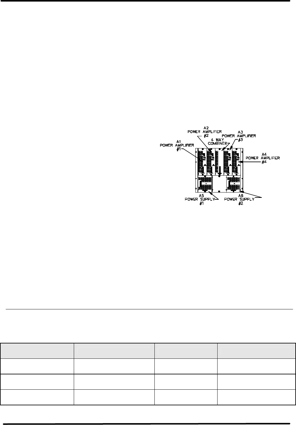
Figure 2-1. 1 kW Power Amplifier
Assembly Racking Plan
In a 1 kW amplifier power amplifier
assembly, the (A5) power supply #1
provides voltages to the (A1) power
amplifier #1 and the (A3) power
amplifier #3 assemblies and the (A6)
power supply #2 provides voltages to the
(A2) power amplifier #2 and the (A4)
power amplifier #4.
2.1.2 System Configurations
Table 2-1: Typical LX Series Analog System Configuration Drawings and Parts Lists
ANALOG SYSTEM
CONFIGURATIONS INTERCONNECT RACKING PLAN PARTS LIST
250W 1303515 1303383 (Transmitter) 1303865
(Translator) 1303862
500W (Transmitter) 1303564
(Translator) 1303563 1303383 (Transmitter) 1303864
(Translator) 1303269
1 kW (Transmitter) 1303564
(Translator) 1303563 1303383 (Transmitter) 1303604
(Translator) 1303272

LX Series Power Amplifier Assembly Chapter 2, Amplifier Assembly Description,
Maintenance & Remote Control Connections
LX Series, Rev. 1 2-4
ANALOG SYSTEM
CONFIGURATIONS INTERCONNECT RACKING PLAN PARTS LIST
2 kW 1303685 1303601 (Transmitter) 1303866
(Translator) 1303828
3 kW 1304066 1304075 (Transmitter) 1304068
4 kW 1304127 1304133 (Transmitter) 1304206
5 kW 1304278 1304277 (Transmitter) 1304276
6 kW 1304311 1304310 (Transmitter) 1304325
NOTE: Refer to Table 2-1 for the
Interconnect, Racking Plan and Parts
List Numbers for your system. The
actual drawings and parts lists are
located in Appendix B of this manual.
A Drawing List of the order the
drawings appear in the Appendix is
found at the beginning of the section.
2.1.2.1 250 Watt, 500 Watt or 1kW
Output System Configurations
In a 250 Watt system, the output of the
(A3) power amplifier chassis assembly at
the 7/16” connector J203 is cabled to (A9)
the bandpass filter for the system. In a
500 Watt or 1 kW system, the output of
the (A3) power amplifier chassis assembly
at the 7/16” connector J205 is also cabled
to the (A9) bandpass filter. The filtered
output connects either directly to (A11)
the output coupler or first to the Optional
1 section or 2 section trap filter if more
filtering is needed and then to the output
coupler. The (A11) coupler assembly
supplies a forward and a reflected power
samples to the (A4) Visual/Aural Metering
Board. The Visual/Aural Metering Board
supplies reflected, visual and aural output
power samples to the exciter/driver for
metering purposes. The reflected sample
connects to TB31-13, the visual sample at
TB31-14 and the aural output power
sample at TB31-15. The RF output for the
transmitter is at J2 the 7/8” EIA connector
on the (A11) coupler assembly.
2.1.2.2 2 kW Output System
Configuration
In a 2 kW system, the output of the (A3)
and the (A6) power amplifier chassis
assemblies, at the “7/16” connectors
J205, are cabled to (A7) the hybrid
combiner for the system, mounted to the
input of the bandpass filter. A 500 Watt
reject load (A9) connects to J4 on the
hybrid combiner to dissipate reject
power. A thermal switch (A9-A1) is
mounted to the reject load and supplies
an overtemperature fault, at 175º F., to
the driver assembly, at TB30-7 & TB30-
15, if a problem occurs in the output
lines. NOTE: If an overtemperature fault
occurs, it must be manually reset on the
system controller after repairs are made.
The combined output of the hybrid
combiner at the “7/8” Jack J3 is
connected to J1 on the bandpass filter.
The filtered output of the bandpass filter
is either cabled directly to the (A11)
output coupler or first to the 1 or 2
section trap filter and then to the output
coupler. The (A11) coupler assembly
supplies a forward and a reflected power
samples to the (A4) Visual/Aural
Metering Board. The Visual/Aural
Metering Board supplies reflected, visual
and aural output power samples to the
exciter/driver for metering purposes.
The reflected sample connects to TB31-
13, the visual sample at TB31-14 and the
aural output power sample at TB31-15.
The RF output for the transmitter is at J2
the 7/8” EIA connector on the (A11)
coupler assembly.
2.1.2.3 3kW Output System
Configuration
In a 3 kW system, the outputs of A3, A6
and A13 power amplifier chassis
assemblies, at the “N” connectors J205,
are cabled to (A7) the hybrid combiner
for the system mounting facing the rear
of the cabinet. A 500 Watt reject load
(A18), mounted on the roof of the
cabinet, connects to J4 on the hybrid
combiner to dissipate reject power.
Another 500 Watt reject load (A9), also

LX Series Power Amplifier Assembly Chapter 2, Amplifier Assembly Description,
Maintenance & Remote Control Connections
LX Series, Rev. 1 2-5
mounted on the roof, connects to J5 on
the hybrid combiner to dissipate reject
power. Thermal switches (A9-A1 & A18-
A1) are mounted to the reject loads and
supply overtemperature faults, at 175º F.,
to the driver assembly at TB30-7 & 15, if
a problem occurs in the output lines.
NOTE: If an overtemperature fault occurs,
it must be manually reset on the system
controller after repairs are made.
The combined output of the hybrid
combiner is cabled to the externally
mounted assemblies, which consist of
(A8) the bandpass filter, (A12) the output
trap filter and (A11) the output coupler.
The output coupler assembly supplies a
forward and a reflected sample to the
(A44) Visual/Aural Metering Board. The
Visual/Aural Metering Board supplies
samples to the exciter/driver for metering
purposes. The reflected sample connects
to TB31-13, the visual sample to TB31-14
and aural output power sample to TB31-
15. The RF output for the transmitter is
at J2 the 3-1/8” EIA connector on the
(A11) output coupler assembly.
2.1.2.4 4kW Output System
Configuration
In a 4 kW system, the outputs of the four
power amplifier chassis assemblies must
be combined. This is accomplished by
combining two power amplifier chassis
assemblies, creating two outputs then
combing these into one output. In the
(A1) cabinet assembly, the outputs of the
(A1-A3 and A1-A6) power amplifiers at
the “7/16” connectors J205, are cabled to
the (A1-A7) hybrid combiner, mounted to
the input jack of the (A1-A8) bandpass
filter. A 1 kW reject load (A1-A9), that
dissipates reject power, is mounted on a
shelf inside the (A1) cabinet and is
connected to (J4) on the hybrid combiner.
A thermal switch (A1-A9-A1) is mounted
to the reject load and supplies an
overtemperature fault, at 175º F., to the
driver assembly at TB30-7 & 15, if a
problem occurs in the output lines for the
(A1) amplifier cabinet. The combined
output at (A1-A7-J3) of the hybrid
combiner connects to the (A1-A8)
bandpass filter for filtering before it is
connected either directly to the “7/8”
Jack J1 on (A3) the 2 way combiner
assembly mounted on the roof of the
cabinets, or through the optional (A1-
A12) trap filter and then to the 2 way
combiner.
In the (A2) cabinet, the outputs of the
(A2-A3 and A2-A6) power amplifiers at
the “7/16” connectors J205, are cabled to
(A2-A7) hybrid combiner. A 1 kW reject
load (A2-A9) connects to (J4) on the
hybrid combiner to dissipate reject
power. A thermal switch (A2-A9-A1) is
mounted to the reject load and supplies
an overtemperature fault, at 175º F., to
the driver assembly at TB30-7 & 15, if a
problem occurs in the output lines for the
(A2) amplifier cabinet. The combined
output at (A2-A7-J3) of the hybrid
combiner connects to the (A2-A8)
bandpass filter for filtering before it is
connected either directly to the “7/8”
Jack J2 on (A3) the 2 way combiner
assembly mounted on the roof of the
cabinets, or through the optional (A2-
A12) trap filter and then to the 2 way
combiner. The combined output of the
(A3) 2 way combiner at the 1-5/8”
connector (A3-J3) is connected to the
input of the (A4) output coupler. The
output coupler assembly supplies a
forward power sample at (A4-J3) and a
reflected sample at (A4-J6) to the (A44)
Visual/Aural Metering Board. The
Visual/Aural Metering Board supplies a
reflected power sample to TB31-13, a
visual power sample to TB31-14 and
aural power sample to TB31-15 on the
exciter/driver for metering purposes.
The RF output for the transmitter is at J2
the 1-5/8” connector on the A4 output
coupler assembly.
2.1.2.5 5kW Output System
Configuration
In a 5 kW system, the outputs of the five
power amplifier chassis assemblies must
be combined. This is accomplished by
combining three power amplifier chassis
assemblies, creating one combined

LX Series Power Amplifier Assembly Chapter 2, Amplifier Assembly Description,
Maintenance & Remote Control Connections
LX Series, Rev. 1 2-6
output, and combining the other two
power amplifier chassis assemblies,
creating another combined output. The
two combined outputs are then combined
into one output. In the (A1) cabinet
assembly, the outputs of the (A1-A6 and
A1-A3) power amplifiers at the “7/16”
connectors J205, are cabled to the J1 and
J2 input jacks of (A1-A7) a hybrid
combiner. A 500 Watt reject load (A1-
A18), that dissipates reject power, is
mounted near the top of the (A1) cabinet
and is connected to (J4) on the hybrid
combiner. A thermal switch (A1-A18-A1)
is mounted to the reject load and supplies
an overtemperature fault, at 175º F., to
the driver assembly at TB30-7 & 15, if a
problem occurs in the output lines for the
(A1) amplifier cabinet. A 1.5 kW reject
load (A1-A9), that dissipates reject power,
is mounted beside the 500W load in the
(A1) cabinet and is connected to (A3-J4) a
2 way hybrid combiner. A thermal switch
(A1-A9-A1) is mounted to the reject load
and supplies an overtemperature fault, at
175º F., to the driver assembly at TB30-7
& 15, if a problem occurs in the output
lines for the transmitter. This fault is in
parallel with the other fault line. The
combined output of the A1 cabinet at (A1-
A7-J3) of the hybrid combiner connects to
(J2) one of the input jacks to (A3) the 2
way combiner mounted on the roof of the
cabinets.
In the (A2) cabinet, the outputs of the
(A2-A6, A2-A3 and A2-A13) power
amplifiers at the “7/16” connectors J205,
are cabled to (A2-A7) a hybrid combiner.
A 500W reject load (A2-A9) connects to
(J4) on the hybrid combiner to dissipate
reject power. A thermal switch (A2-A9-
A1) is mounted to the reject load and
supplies an overtemperature fault, at
175º F., to the driver assembly at TB30-7
& 15, if a problem occurs in the combining
of the power amplifiers in the (A2)
amplifier cabinet. A 500W reject load
(A2-A5) connects to (J5) on the hybrid
combiner to dissipate reject power. A
thermal switch (A2-A5-A1) is mounted to
the reject load and supplies an
overtemperature fault, at 175º F., to the
driver assembly at TB30-7 & 15, if a
problem occurs in the output lines for the
(A2) amplifier cabinet. . These faults
are in parallel with the other fault lines.
The combined output of the A2 cabinet at
(A2-A7-J6) of the hybrid combiner
connects to the other input jack (J1) on
(A3) the 2 way combiner mounted on the
roof of the cabinets. J4 on the combiner
connects to a 1.5 kW reject load (A1-A9),
that dissipates reject power, which is
mounted inside the cabinet facing the
rear of the (A1) cabinet. A thermal
switch (A1-A9-A1) is mounted to the
reject load and supplies an
overtemperature fault, at 175º F., to the
driver assembly at TB30-7 & 15, if a
problem occurs in the output lines for the
(A2) amplifier cabinet. This fault is in
parallel with the other overtemperature
fault lines.
The combined output of the (A3)
combiner at J3 connects to the (A8)
bandpass filter for filtering before it is
connected through the (A12) trap filter,
for additional filtering, to the input of the
(A11) output coupler. The output coupler
assembly supplies a forward power
sample at (A1-A44-J1) and a reflected
sample at (A1-A44-J2) to the (A44)
Visual/Aural Metering Board, mounted in
the (A1) cabinet. The Visual/Aural
Metering Board supplies a reflected
power sample to TB31-13, a visual power
sample to TB31-14 and aural power
sample to TB31-15 on the exciter/driver
for metering purposes. The RF output for
the transmitter is at J2 the 3-1/8”
connector on the A11 output coupler
assembly.
2.1.2.6 6kW Output System
Configuration
In a 6 kW system, the outputs of the six
power amplifier chassis assemblies must
be combined. This is accomplished by
combining three power amplifier chassis
assemblies, creating one combined
output, and combining the other three
power amplifier chassis assemblies,
creating another combined output. The
two combined outputs are then combined

LX Series Power Amplifier Assembly Chapter 2, Amplifier Assembly Description,
Maintenance & Remote Control Connections
LX Series, Rev. 1 2-7
into one output. In the (A1) cabinet
assembly, the outputs of the (A1-A3, A1-
A6, and A1-A13) power amplifiers at the
“7/16” connectors J205, are cabled to the
J1, J2 & J3 input jacks of (A1-A7) a 3 way
hybrid combiner. A 500 Watt reject load
(A1-A9), that dissipates reject power, is
mounted on the roof of the (A1) cabinet
and is connected to (J5) on the hybrid
combiner. A thermal switch (A1-A9-A1) is
mounted to the reject load and supplies
an overtemperature fault, at 175º F., to
the driver assembly at TB30-7 & 15, if a
problem occurs in the output lines for the
(A1) amplifier cabinet. Another 500 Watt
reject load (A1-A18), that dissipates reject
power, is mounted on the roof of the (A1)
cabinet and is connected to (J4) on the
hybrid combiner. A thermal switch (A1-
A18-A1) is mounted to the reject load and
supplies an overtemperature fault, at
175º F., to the driver assembly at TB30-7
& 15, if a problem occurs in the output
lines for the (A1) amplifier cabinet. This
fault is in parallel with the other fault line.
The combined output of the A1 cabinet at
(A1-A7-J6) of the hybrid combiner
connects to one of the input jacks (J1) on
(A3) the 2 way combiner mounted on the
roof of the cabinets.
In the (A2) cabinet, the outputs of the
(A2-A3, A2-A6, and A3-A13) power
amplifiers at the “7/16” connectors J205,
are cabled to (A2-A7) hybrid combiner. A
500 Watt reject load (A2-A9) connects to
(J4) on the hybrid combiner to dissipate
reject power. A thermal switch (A2-A9-
A1) is mounted to the reject load and
supplies an overtemperature fault, at
175º F., to the driver assembly at TB30-7
& 15, if a problem occurs in the output
lines for the (A2) amplifier cabinet.
Another 500 Watt reject load (A2-A18),
that dissipates reject power, is mounted
on the roof of the (A2) cabinet and is
connected to (J4) on the hybrid combiner.
A thermal switch (A2-A18-A1) is mounted
to the reject load and supplies an
overtemperature fault, at 175º F., to the
driver assembly at TB30-7 & 15, if a
problem occurs in the output lines for the
(A2) amplifier cabinet.
The combined output of the A2 cabinet at
(A2-A7-J6) of the hybrid combiner
connects to the other input jack (J2) on
(A3) the 2 way combiner mounted on the
roof of the cabinets. J4 on the combiner
connects to a 1.5 kW reject load (A5),
that dissipates reject power, which is
mounted inside the cabinet facing the
rear of the (A2) cabinet. A thermal
switch (A5-A1) is mounted to the reject
load and supplies an overtemperature
fault, at 175º F., to the driver assembly
at TB30-7 & 15, if a problem occurs in
the output lines for the (A2) amplifier
cabinet. This fault is in parallel with the
other overtemperature fault lines. The
combined output of the (A3) combiner
connects to the (A8) bandpass filter for
filtering before it is connected through
the (A12) trap filter, for additional
filtering, to the input of the (A11) output
coupler. The output coupler assembly
supplies a forward power sample at (A1-
A44-J1) and a reflected sample at (A1-
A44-J2) to the (A44) Visual/Aural
Metering Board. The Visual/Aural
Metering Board supplies a reflected
power sample to TB31-13, a visual power
sample to TB31-14 and aural power
sample to TB31-15 on the exciter/driver
for metering purposes. The RF output for
the transmitter is at J2 the 3-1/8”
connector on the A11 output coupler
assembly.
NOTE: If an overtemperature fault
occurs in any system configuration, it
must be manually reset on the system
controller after repairs are made.
The LX Series power amplifier assembly
is made up of the modules and
assemblies listed in Table 2-3.
LX Series Power Amplifier Assembly Chapter 2, Amplifier Assembly Description,
Maintenance & Remote Control Connections
LX Series, Rev. 1 2-8
Table 2-3: Typical LX Series Power Amplifier Chassis Assemblies
ASSEMBLY
DESIGNATOR ASSEMBLY NAME PART NUMBER
125W/250W/500 Watt Chassis Assembly 1303958
Or 500W Upgradeable & 1 kW Chassis
Assembly 1303953
A3 & (Opt A6 & A13) Power Amplifier Assembly, 250 Watt 1302868
Power Supply Assembly 1302863
Opt A5 2 or 4 Way Splitter Assembly 1303567 (2 Way)
1303347 (4 Way)
A11 Coupler Assembly 450029
A4 or A44 Visual/Aural Metering Board 1265-1309
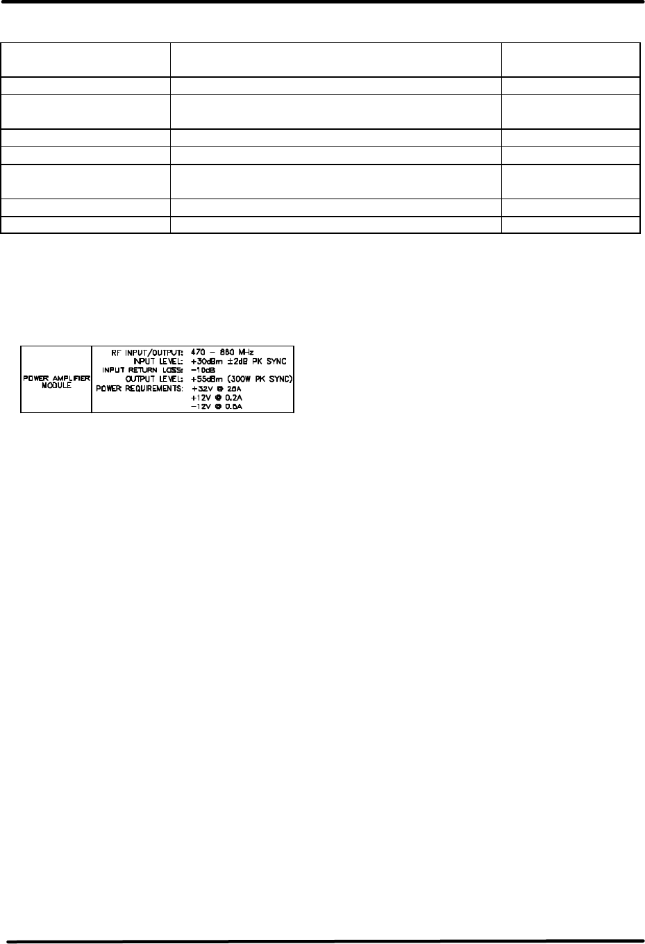
2.1.3 Power Amplifier Module
Assembly, 250 Watt (1302868;
Appendix B)
The 250 Watt Power Amplifier Module
Assembly is made up of (A6) an Amplifier
Control Board (1303682, 1301962 or
1303702), (A1) a UHF Phase/Gain Board
(1303213), (A2) a 150 Watt Driver Pallet
Assembly (1303293), (A3 & A4) two RF
Module Pallets, Philips (1300116), and
(A5) a 2-Way Combiner Board
(1303208).
The Power Amplifier Module contains
Broadband LDMOS amplifiers that cover
the entire UHF band with no tuning
required. Each module amplifies the RF
to a nominal 300W output power. The
Power Amplifier assembly is used to
amplify the RF output of the
Transmitter/Exciter Driver. A cable,
located on the rear chassis, connects the
RF output from the Exciter/Driver at J25
to J200 the RF input to the PA Assembly.
This module contains RF monitoring
circuitry for both an analog and a digital
system. Control and monitoring lines to
the Power Amplifier module are routed
through the floating blind-mate
connector of the Control &
Monitoring/Power Supply module.
The Transmitter/Exciter Driver Power
Amplifier module and any External
Power Amplifier modules contain the
same control and monitoring board.
This board monitors RF output power,
RF reflected power, the current draw of
amplifier sections, the supply voltage,
and the temperature of the PA heat sink.
The RF power detector circuit outputs
vary with operating frequency. These
circuits must be calibrated at their
intended operating frequency. The
following front panel potentiometers are
used to set the Power Amplifier
Calibrations in Analog Systems.
R201 Reflected Power Cal
R202 Forward Power Cal
R204 Meter Offset Zero
In analog systems, the Aural power of
an Exciter Driver Power Amplifier and
the Aural power of any external
amplifier will not be reported by the
system Control Monitoring module.
Additionally the Visual power of these
amplifiers, is reported as Forward Power
just like in digital systems. In analog
systems, aural and visual power will only
be reported for the final system RF
output.
If the Control Monitoring module is
monitoring a 10-100 Watt Analog
Transmitter, system power is measured
in the Power Amplifier module. The
wired connections are transferred
through the power supply connector to
LX Series Power Amplifier Assembly Chapter 2, Amplifier Assembly Description,
Maintenance & Remote Control Connections
LX Series, Rev. 1 2-9
the backplane board on a five position
header. All four positions of control
board switch SW1 must be set on to
route these lines as the system's RF
power signals. In systems of output
power greater than 100 Watts, system
power is monitored by an external
module that is connected to TB31 and
control board SW1 switches must be set
off.
The Forward Power of the
Transmitter/Exciter Driver Power
Amplifier module is routed to the
Upconverter module as AGC #1. A
system over-drive condition is detected
when this value rises above 0.9 VDC.
When an over-drive condition is
detected, the Upconverter module
reduces its RF output level. For values
less than 0.9 VDC, the Upconverter uses
this voltage for automatic gain.
Table 2-4. Power Amplifier Status Indicator
LED FUNCTION
ENABLED
(Green) When lit Green, it indicates that the PA is in the Operate Mode. If a Mute
occurs, the PA will remain Enabled, until the input signal is returned.
DC OK
(Green) When lit Green, it indicates that the fuse protected DC inputs to the PA
module are OK.
TEMP
(Green) When lit Green, it indicates that the temperature of the heatsink
assembly in the module is below 78°C.
MOD OK
(Green) When lit Green, it indicates that the PA Module is operating and has no
faults.
MOD OK
(Red)
If the Module OK LED is Red and blinking a fault is present.
1 Blink indicates Amplifier Current Fault.
2 Blinks indicate Temperature Fault.
3 Blinks indicate +32V Power Supply Over Voltage Fault.
4 Blinks indicate +32V Power Supply Under Voltage Fault.
5 Blinks indicate Reflected Power Fault.
6 Blinks indicate +12V or –12V Power Supply Fault.
Table 2-5. Power Amplifier Control Adjustments
POTENTIOMETERS DESCRIPTION
RFL CAL Adjusts the gain of the Reflected Power monitoring circuit
VISUAL CAL Adjusts the gain of the Visual / Forward Power monitoring circuit
METER ZERO Adjusts the offset of the Forward Power monitoring circuit
Table 2-6. Power Amplifier Sample
DISPLAY FUNCTION
FWD SAMPLE RF sample of the amplified signal being sent out the module on J25.

LX Series Power Amplifier Assembly Chapter 2, Amplifier Assembly Description,
Maintenance & Remote Control Connections
LX Series, Rev. 1 2-10
2.1.4 Power Supply Module
Assembly, LX Series (1302863;
Appendix B)
The Power Supply Module Assembly is
made up of (A1) a +32V/2000W
Switching Power Supply and (A2) a
±12V/40W Switching Power Supply.
The power supply module provides the
+32 VDC and the +12 VDC and –12 VDC
to the power amplifier module assembly.
2.1.5 Front Panel Display Screens
NOTE: In systems with two exciters and
an exciter switcher, first perform the
following procedure with Exciter A as the
On Air Exciter then select Exciter B as
the On Air Exciter and repeat the
procedure. Switcher system must be in
Manual.
A 4 x 20 display located on the front of
the Control & Monitoring/Power Supply
Module is used in the LX Series
transmitter for control of the operation
and display of the operating parameters
of the entire transmitter. Refer to
Chapter 3 for detailed information on
the LCD menu screens.
2.2 System Operation
When the transmitter is in operate, as set
by the menu screen located on the
Control & Monitoring Module in the
exciter/driver assembly. The IF
Processor will be enabled, the mute
indicator on the front panel will be
extinguished. The +32 VDC stage of the
Power Supply in the Control & Monitoring
Module is enabled, the operate indicator
on the front panel is lit and the DC OK on
the front panel should also be green.
The enable and DC OK indicators on the
PA Module will also be green.
When the transmitter is in standby. The
IF Processor will be disabled, the mute
indicator on the front panel will be red.
The +32 VDC stage of the Power Supply
in the Control & Monitoring Module is
disabled, the operate indicator on the
front panel will be extinguished and the
DC OK on the front panel should remain
green. The enable indicator on the PA
Module is also extinguished.
If the transmitter does not switch to
Operate when the operate menu is
switched to Operate, check that all faults
are cleared and that the remote control
terminal block stand-by signal is not
active.
The transmitter can be controlled by the
presence of a modulated input signal. If
the input signal to the transmitter is lost;
the transmitter automatically cutbacks
and the input fault indicator on the IF
Processor module lights. When the video
input signal returns, the transmitter
automatically returns to full power and
the input fault indicator is extinguished.
2.2.1 Principles of Operation
Operating Modes
This transmitter is either operating or in
standby mode. The sections below
discuss the characteristics of each of
these modes.
Operate Mode
Operate mode is the normal mode for
the transmitter when it is providing RF
power output. To provide RF power to
the output, the transmitter will not be in
mute. Mute is a special case of the
operate mode where the +32 VDC
section of the power supply is enabled
but there is no RF output power from
the transmitter. This condition is the
result of a fault condition that causes
the firmware to hold the IF Processor
module in a mute state.

LX Series Power Amplifier Assembly Chapter 2, Amplifier Assembly Description,
Maintenance & Remote Control Connections
LX Series, Rev. 1 2-11
Operate Mode with Mute Condition
The transmitter will remain in the
operate mode but will be placed in mute
when the following fault conditions
exists in the transmitter.
• Upconverter is unlocked
• Upconverter module is not present
• IF Processor module is not present
• Modulator (if present) is in
Aural/Visual Mute
Entering Operate Mode
Entering the operate mode can be
initiated a few different ways by the
transmitter control board. A list of the
actions that cause the operate mode to
be entered is given below:
• A low on the Remote Transmitter
Operate line.
• User selects "OPR" using switches
and menus of the front panel.
• Receipt of an “Operate CMD” over
the serial interface.
There are several fault or interlock
conditions that may exist in the
transmitter that will prevent the
transmitter from entering the operate
mode. These conditions are:
• Power Amplifier heat sink
temperature is greater than 78°C.
• Transmitter is Muted due to the
conditions listed above.
• Power Amplifier Interlock is high
indicating that the amplifier is not
installed.
Standby Mode
The standby mode in the transmitter
indicates that the output amplifier of the
transmitter is disabled.
Entering Standby Mode
Similar to the operate mode, the
standby mode is entered using various
means. These are:
• A low on the Remote Transmitter
Stand-By line.
• Depressing the “STB” key on
selected front panel menus.
• Receipt of a “Standby CMD” over the
serial interface.
Auto Standby Mode
The FCC requires that certain
transmitters automatically switch to
standby operation on loss of video input.
The LX Series transmitter incorporates
this feature as a user configurable
setting. When Auto Standby on
modulation loss is selected in the set-up
menus, the transmitter temporarily
switches to standby after ten seconds of
modulation loss. When the modulated
signal as reported by the IF Processor
module is again present, the transmitter
automatically returns to Operate mode.
This feature is implemented in
transmitter software version 1.4 and
above.
RF System Interlock
A RF System Interlock signal is provided
through TB30-5. When this interlock
circuit is completed to ground such as
through a jumper between TB30-5 and
TB30-15, the transmitter is allowed to
operate. If this circuit is opened, the
transmitter switches to a Mute condition.
The interlock must be in place for the
system to operate. This interlock circuit
may be completed through coax relay
contacts and/or reject load contact
closures to assure the RF output system
is available to receive the transmitter's
output RF signal before the transmitter
is allowed to operate. This feature is
implemented in transmitter software
version 1.4 and above.
Operating Frequency
NOTE: The exact output frequency of
the transmitter was set at the factory
and needs no customer adjustment.

LX Series Power Amplifier Assembly Chapter 2, Amplifier Assembly Description,
Maintenance & Remote Control Connections
LX Series, Rev. 1 2-12
The LX Series transmitter controller is
designed to operate on UHF and VHF
frequencies. The frequency can be set
to one of the standard UHF or VHF
channel frequencies, or it can be set to a
custom frequency using the built in
software and the set-up menu located
on the LCD Display screen. Since RF
performance of the transmitter requires
different hardware for different
frequency bands, not all frequency
configurations are valid for a specific
transmitter. The Power detectors in the
transmitter have frequency dependency,
therefore detectors of power amplifiers
are calibrated at their frequency of use.
The detectors for System RF monitoring
are also calibrated at the desired
frequency of use. Refer questions about
channel changes to the Axcera field
support department at 724-873-8100.
2.3 Maintenance
The LX Series Transmitter is designed
with components that require little or no
periodic maintenance except for the
routine cleaning of the fans and the front
panels of the modules. The amount of
time between cleanings depends on the
conditions within the transmitter room.
While the electronics have been designed
to function even if covered with dust, a
heavy buildup of dust, dirt, or insects will
affect the cooling of the components.
This could lead to a thermal shutdown or
the premature failure of the affected
modules.
When the front panels of the modules
become dust covered, the top covers
should be taken off and any accumulated
foreign material should be removed. A
vacuum cleaner, utilizing a small, wand-
type attachment, is an excellent way to
suction out the dirt. Alcohol and other
cleaning agents should not be used
unless you are certain that the solvents
will not damage components or the silk-
screened markings on the modules and
boards. Water-based cleaners can be
used, but do not saturate the
components. The fans and heatsinks
should be cleaned of all dust or dirt to
permit the free flow of air for cooling
purposes.
It is recommended that the operating
parameters of the amplifier assembly and
transmitter be recorded from the LEDs on
the modules and the LCD system
metering on the control/monitoring
module at least once a month. It is
suggested that this data be retained in a
rugged folder or envelope.
2.4 Customer Remote Connections
NOTE: For dual exciter systems refer to
chapter 2 of Volume 1 for detailed
information.
The remote monitoring and operation of
the transmitter is provided through
terminal blocks TB30 and TB31 located
on the rear of the chassis assembly. If
remote connections are made to the
transmitter, they must be made through
terminal blocks TB30 and TB31 at the
positions noted on the transmitter
interconnect drawing and Table 2-7.
TB30
TB31

LX Series Power Amplifier Assembly Chapter 2, Amplifier Assembly Description,
Maintenance & Remote Control Connections
LX Series, Rev. 1 2-13
Table 2-7: LX Series Chassis Assembly Hard Wired Remote Interface Connections to
TB30 or TB31, which are 18 position Terminal Blocks located on the rear
of the Assembly
Signal Name Pin
Designations Signal Type/Description
RMT Transmitter
State TB30-1 Discrete Open Collector Output - A low indicates that the
transmitter is in the operate mode.
RMT Transmitter
Interlock TB30-2
Discrete Open Collector Output - A low indicated the
transmitter is OK or completes an interlock daisy chain.
When the transmitter is not faulted, the interlock circuit
is completed.
RMT Transmitter
Interlock
Isolated Return TB30-3
Ground - Configurable ground return which can be either
jumpered directly to ground or it can be the “source” pin
of an FET so that the transmitter interlock can be daisy
chained with other transmitters. This signal does not
directly interface to the microcontroller.
RMT AUX IO 1 TB30-4
Discrete Open Collector Inputs, Discrete Open Drain
Outputs, or 0 - 5 VDC Analog Input - When used as an
output, this line is pulled to +5 VDC with a 1.0 kO
resistor for logic high and pulled to ground for a low. A
diode allows this line to be pulled up to 12 VDC. When
used as a digital input, this line considers all values over
2 Volts as high and those under 1 volt as low. As an
analog input, this line is protected by a 5.1 zener diode.
RMT RF System
Interlock TB30-5
When this signal's circuit is completed to ground such as
through a jumper between TB30-5 and TB30-15, the
transmitter is allowed to operate. If this circuit is
opened, the transmitter switches to a Mute condition.
Implemented in transmitter software versions 1.4 and
above.
RMT
Transmitter
Operate TB30-6 Discrete Open Collector Input - A pull down to ground on
this line indicates that the transmitter is to be placed into
the operate mode.
RMT
Transmitter
Stand-By TB30-7
Discrete Open Collector Input - A pull down to ground on
this line indicates that the transmitter is to be placed into
the standby mode.
RMT Power
Raise TB30-8 Discrete Open Collector Input - A pull down to ground on
this line indicates that the transmitter power is to be
raised.
RMT Power
Lower TB30-9 Discrete Open Collector Input - A pull down to ground on
this line indicates that the transmitter power is to be
lowered.
RMT
System Reflect
Power TB30-10
Analog Output - 0 to 4.0 V- This is a buffered loop
through of the calibrated “System Reflected Power ” and
indicates the transmitter's reflected output power. The
scale factor is 25%/3.2V.
RMT System
Visual/Forward
Power TB30-11
Analog Output - 0 to 4.0 V- This is a buffered loop
through of the calibrated “System Visual/Avg. Power ”.
Indicates the transmitter's Visual / Average power. Scale
factor is 100%/3.2V.

LX Series Power Amplifier Assembly Chapter 2, Amplifier Assembly Description,
Maintenance & Remote Control Connections
LX Series, Rev. 1 2-14
Signal Name Pin
Designations Signal Type/Description
RMT
System Aural
Power TB30-12
Analog Output - 0 to 4.0 V- This is a buffered loop
through of the calibrated “System Aural Power ”.
Indicates the transmitter's forward Aural output power.
The scale factor is 100%/3.2V.
RMT Spare 1 TB30-13 Remote connection to spare module - Use is TBD.
RMT Spare 2 TB30-14 Remote connection to spare module - Use is TBD.
System Reflect
Power TB31-13 Analog Input - 0 to 1.00 V- This is the input of the
“System Reflected Power ” indicating the transmitter's
reflected output power. The scale factor is 25%/0.80V.
System Visual/
Forward Power TB31-14
Analog Input - 0 to 1.00 V- This is the input of the
“System Visual / Forward Power ” indicating the
transmitter's forward Visual / Forward output power. The
scale factor is 100%/0.80V.
System Aural
Power TB31-15
Analog Input - 0 to 1.00 V- This is the input of the
“System Aural Power ” indicating the transmitter's
forward Aural output power. The scale factor is
100%/0.80V.
IF Processor
IF Signal Select TB31-3
Discrete Open Collector Input - A low indicates that the
modulator IF source is to be used by the IF Processor
module. When floating an analog IP Processor module
may use the Modulated IF Input if the IF Processor sled
is so configured.
IF Processor
DLC Voltage TB31-4 Analog Output - 0 to 5.00 V- This is the input of IF
Processor module for digital system RF output power
control.
UC AGC #2
Voltage TB31-5
Auxiliary Analog Input - 0 to 1V- This voltage is used by
the Upconverter for gain control. Linear signal with
display resolution of 0.01 %. Primary signal source is
J34-1.
RMT Ground TB30-15, and
17 Ground pins available through Remote
RMT Ground TB31-1, 2, 6
to 12, and 17 Ground pins available through Remote
RMT +12 VDC TB30-16
TB31-16 +12 VDC available through Remote w/ 2 Amp re-settable
fuse
RMT -12 VDC TB30-18
TB31-18 -12 VDC available through Remote w/ 2 Amp re-settable
fuse
LX Series Power Amplifier Assembly Chapter 3, Site Considerations,
Installation and Setup Procedures
LX Series, Rev. 1 3-1
Chapter 3
Site Considerations, Installation and Setup Procedures
Table 3-1: LX Series Transmitters AC Input and Current Requirements.
Transmitter Voltage Current
250 Watt 220 VAC 10 Amps to the Exciter/Amplifier Cabinet
500 Watt 220 VAC 15 Amps to the Exciter/Amplifier Cabinet
1000 Watt 220 VAC 25 Amps to the Exciter/Amplifier Cabinet
2000 Watt 220 VAC 45 Amps to the Exciter/Amplifier Cabinet
3000 Watt 220 VAC 65 Amps to the Exciter/Amplifier Cabinet
220 VAC 45 Amps to the Exciter/Amplifier Cabinet
4000 Watt 220 VAC 40 Amps to the Amplifier Cabinet
220 VAC 55 Amps to the Exciter/Amplifier Cabinet
5000 Watt 220 VAC 50 Amps to the Amplifier Cabinet
220 VAC 65 Amp to the Exciter/Amplifier Cabinet
6000 Watt 220 VAC 60 Amps to the Amplifier Cabinet
3.1 Site Considerations
There are special considerations that need
to be taken into account before the LX
Series Power Amplifier Assembly and
exciter/driver assembly can be installed. For
example, if the installation is completed
during cool weather, a heat-related problem
may not surface for many months, suddenly
appearing during the heat of summer. This
section provides planning information for
the installation and set up of the
transmitter.
The AC input and current requirements for
LX Series transmitters are as shown in
Table 3-1.
NOTES: Transmitters 4000 Watts and
above require two 220 VAC Inputs, one
to each cabinet.
All currents are with a Black picture.
Check that your site has the needed power
requirements. The AC to the transmitter is
controlled by the main circuit breaker there
is no in-cabinet circuit breaker.
The LX Series Transmitters are designed
and built to provide long life with a
minimum of maintenance. The environment
in which they are placed is important and
certain precautions must be taken. The
three greatest dangers to the transmitter
are heat, dirt, and moisture. Heat is
usually the greatest problem, followed by
dirt, and then moisture. Over-temperature
can cause heat-related problems such as
thermal runaway and component failure.
Each amplifier module in the transmitter
contains a thermal interlock protection
circuit that will shut down that module until
the temperature drops to an acceptable
level.
A suitable environment for the transmitter
can enhance the overall performance and
reliability of the transmitter and maximize
revenues by minimizing downtime. A
properly designed facility will have an
adequate supply of cool, clean air, free of
airborne particulates of any kind, and no
excessive humidity. An ideal environment
will require temperature in the range of
40° F to 70° F throughout the year,
reasonably low humidity, and a dust-free
room. It should be noted that this is rarely
if ever attainable in the real world.
However, the closer the environment is to
this design, the greater the operating
capacity of the transmitter.
The fans are designed and built into the
transmitter will remove the heat from
within the modules, but additional means
are required for removing this heat from
the building. To achieve this, a few issues
need to be resolved. The first step is to

LX Series Power Amplifier Assembly Chapter 3, Site Considerations,
Installation and Setup Procedures
LX Series, Rev. 1 3-2
determine the amount of heat to be
removed from the transmitter room. There
are generally three sources of heat that
must be considered. The first and most
obvious is the heat from the transmitter
itself. This amount can be determined for a
1 kW transmitter by subtracting the average
power to the antenna (695 watts) from the
AC input power (4800 watts) and taking this
number in watts (4105) and then
multiplying it by 3.41. This gives a result of
13,998, the BTUs to be removed every
hour. 12,000 BTUs per hour equals one ton.
Therefore, a 1-1/4 ton air conditioner will
cool a 1 kW transmitter.
The second source of heat is other
equipment in the same room. This number
is calculated in the same way as the
equation for BTUs. The third source of heat
is equally obvious but not as simple to
calculate. This is the heat coming through
the walls, roof, and windows on a hot
summer day . Unless the underside is
exposed, the floor is usually not a problem.
Determining this number is usually best left
up to a qualified HVAC technician. There
are far too many variables to even estimate
this number without reviewing the detailed
drawings of the site that show all of the
construction details. The sum of these three
sources is the bulk of the heat that must be
removed. There may be other sources of
heat, such as personnel, and all should be
taken into account.
Now that the amount of heat that must be
removed is known, the next step is to
determine how to accomplish this. The
options are air conditioning, ventilation, or a
combination of the two. Air conditioning is
always the preferred method and is the only
way to create anything close to an ideal
environment.
Ventilation will work quite well if the
ambient air temperature is below 100° F, or
about 38° C, and the humidity is kept at a
reasonable level. In addition, the air
stream must be adequately filtered to
ensure that no airborne particulates of any
kind will be carried into the transmitter. The
combination of air conditioning for summer
and ventilation during the cooler months is
acceptable when the proper cooling cannot
be obtained through the use of ventilation
alone and using air conditioning throughout
the year is not feasible.
Caution: The use of air conditioning
and ventilation simultaneously is not
recommended. This can cause
condensation in the transmitter.
The following precautions should be
observed regarding air conditioning
systems:
1. Air conditioners have an ARI
nominal cooling capacity rating. In
selecting an air conditioner, do not
assume that this number can be
equated to the requirements of the
site. Make certain that the
contractor uses the actual conditions
that are to be maintained at the site
in determining the size of the air
conditioning unit. With the desired
conditioned room temperature
under 80° F, the unit must be
derated, possibly by a substantial
amount.
2. Do not have the air conditioner
blowing directly onto the
transmitter. Under certain
conditions, condensation may occur
on, or worse in the transmitter.
3. Do not separate the front of the
transmitter from the back with the
thought of air conditioning only the
front of the unit. Cooling air is
drawn in at the front of all
transmitters and in the front and
back of others. Any attempt to
separate the front of the transmitter
from the rear of the unit will
adversely affect the flow of cooling
air.
4. Interlocking the transmitter with the
air conditioner is recommended to
keep the transmitter from operating
without the necessary cooling.

LX Series Power Amplifier Assembly Chapter 3, Site Considerations,
Installation and Setup Procedures
LX Series, Rev. 1 3-3
5. The periodic cleaning of all filters is a
must.
When using ventilation alone, the following
general statements apply:
1. The blower, with attendant filters,
should be on the inlet, thereby
pressurizing the room and preventing
dirt from entering the transmitter.
2. The inlet and outlet vents should be
on the same side of the building,
preferably the leeward side. As a
result, the pressure differential
created by wind will be minimized.
Only the outlet vent may be released
through the roof.
3. The inlet and outlet vents should be
screened with 1/8-inch hardware
cloth (preferred) or galvanized
hardware cloth (acceptable).
4. Cooling air should enter the room as
low as practical but in no case higher
than four feet above the floor. The
inlet must be located where dirt,
leaves, snow, etc., will not be carried
in with the cooling air.
5. The exhaust should be located as
high as possible. Some ducting is
usually required to insure the
complete flushing of heated air with
no stagnant areas.
6. The filter area must be large enough
to insure a maximum air velocity of
300 feet per minute through the
filter. This is not a conservative
number but a never-exceed number.
In a dusty or remote location, this
number should be reduced to 150
CFM.
7. The inlet and outlet(s) must have
automatic dampers that close any
time the ventilation blower is off.
8. In those cases in which transmitters
are regularly off for a portion of each
day, a temperature-differential
sensor that controls a small heater
must be installed. This sensor will
monitor inside and outside
temperatures simultaneously. If the
inside temperature falls to within 5°
F of the outside temperature, the
heater will come on. This will
prevent condensation when the
ventilation blower comes on and
should be used even in the summer.
9. A controlled-air bypass system must
be installed to prevent the
temperature in the room from falling
below 40° F during transmitter
operation.
10. The blower should have two speeds,
which are thermostatically
controlled, and be interlocked with
the transmitter.
11. The blower on high speed must be
capable of moving the required
volume of air into a half inch of
water pressure at the required
elevation. The free air delivery
method must not be used.
12. Regular maintenance of the filters, if
used, can not be overemphasized.
13. Above 4000 feet, for external
venting, the air vent on the cabinet
top must be increased to an 8-inch
diameter for a 1-kW transmitter and
to a 10-inch diameter for 5-kW and
6-kW transmitters. An equivalent
rectangular duct may be used but,
in all cases, the outlet must be
increased by 50% through the
outlet screen.
14. It is recommended that a site plan
be submitted to Axcera for
comments before installation
begins.
In calculating the blower requirements,
filter size, and exhaust size, if the total
load is known in watts, 2000 CFM into ½
inch of water will be required for each 5000
watts. If the load is known in BTUs, 2000
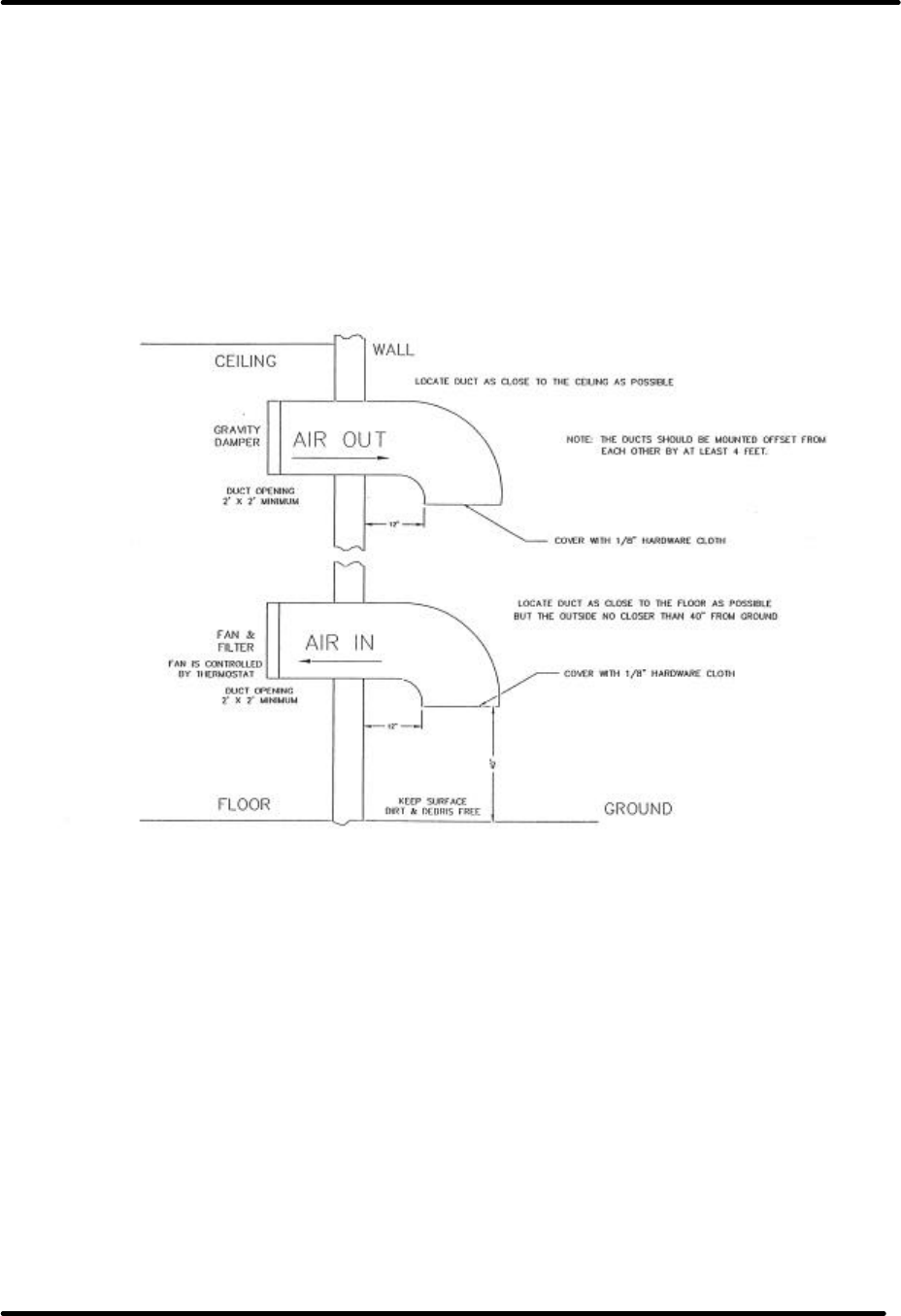
LX Series Power Amplifier Assembly Chapter 3, Site Considerations,
Installation and Setup Procedures
LX Series, Rev. 1 3-4
CFM into ½ inch of water will be required for
each 17,000 BTUs. The inlet filter must be a
minimum of seven square feet, larger for
dusty and remote locations, for each 5000
watts or 17,000 BTUs. The exhaust must be
at least four square feet at the exhaust
screen for each 5000 watts or 17,000 BTUs.
The information presented in this section is
intended to serve only as a general guide
and may need to be modified for unusually
severe conditions. A combination of air
conditioning and ventilation should not be
difficult to design (see Figure 3-1).
System interlocking and thermostat
settings should be reviewed with Axcera.
As with any equipment installation, it is
always good practice to consult the
manufacturer when questions arise. Axcera
can be contacted at (724) 873-8100.
Figure 3-1. 1 kW Minimum Ventilation Configuration
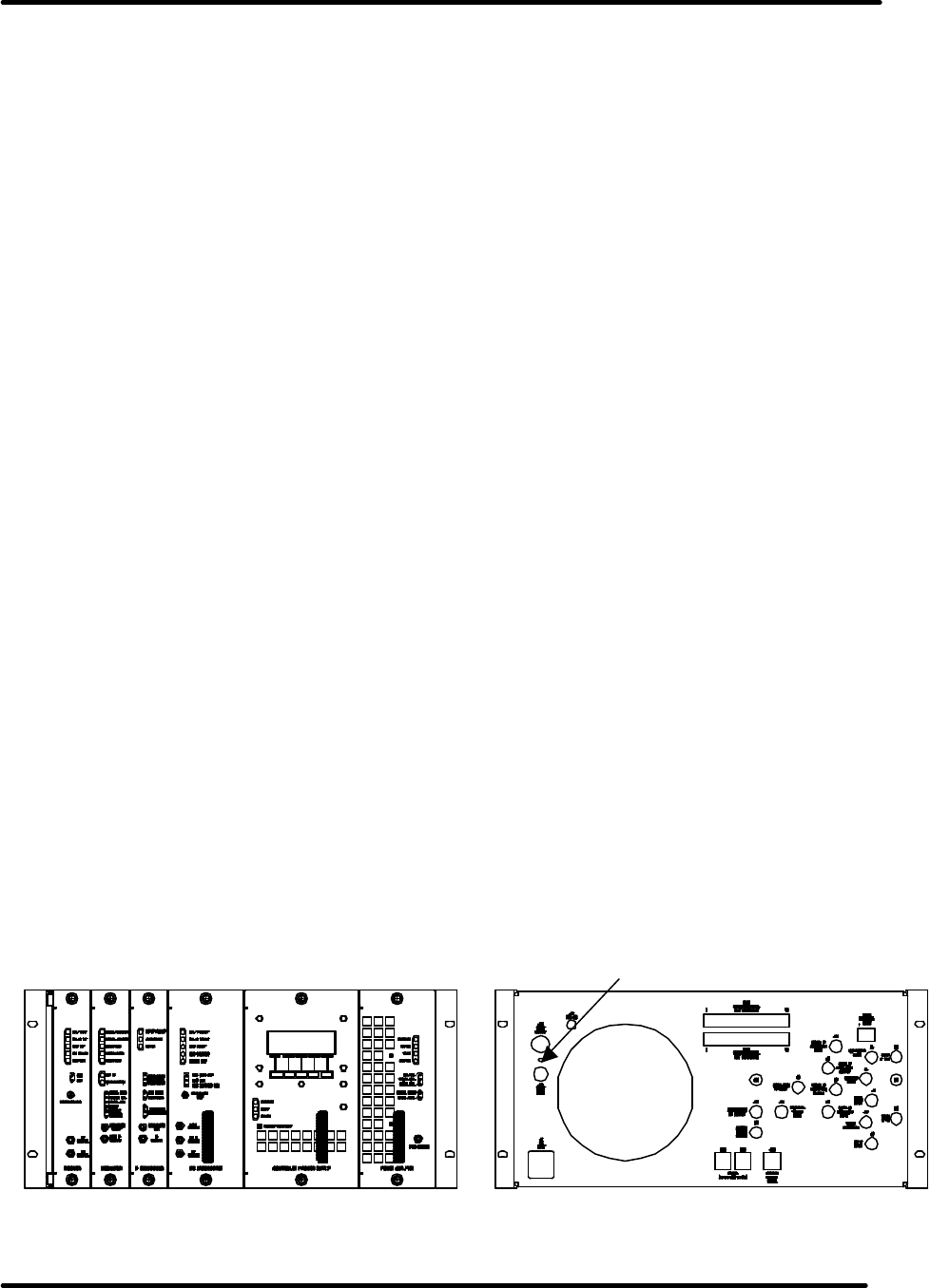
LX Series Power Amplifier Assembly Chapter 3, Site Considerations,
Installation and Setup Procedures
LX Series, Rev. 1 3-5
NOTE: Typically the transmitter is
shipped already mounted in the
cabinets. If this is true the following
sections may be skipped.
3.2 Unpacking the Chassis
w/modules, bandpass filter and
optional trap filter
Thoroughly inspect the chassis with
modules and all other materials upon
their arrival. Axcera certifies that upon
leaving our facility the equipment was
undamaged and in proper working order.
The shipping containers should be
inspected for obvious damage that
indicates rough handling.
Remove the chassis and modules, along
with bandpass filter and optional trap
Filter, from the crates and boxes. Check
for dents and scratches or broken
connectors, switches, display, or
connectors. Any claims against in-transit
damage should be directed to the carrier.
Inform Axcera as to the extent of any
damage as soon as possible.
The modules are mounted to the chassis
assembly with slides that are on the top
and the bottom of the modules. There
are two thumb screws on the front panel
that hold each of the modules in place.
3.3 Installing the Chassis w/modules
and filters
The exciter/driver and power amplifier
chassis assemblies are made to mount in
a standard 19” rack. The chassis
assemblies mount using the four #10
clearance mounting holes on the ends.
The chassis should be positioned; to
provide adequate air intake into the front
and the air exhaust of the fan in the rear;
the ability to slide the modules out for
replacement purposes; the installation of
the bandpass filter; optional trap filter;
the coupler assembly; and output
transmission line. The chassis or cabinet
in which it is mounted should be
grounded using copper strapping
material.
NOTE: To remove the driver/power
amplifier module, mounted in the
exciter/driver assembly, the input and
output cables must be removed from the
rear of the module and also a 6/32” x ½”
Philips screw, mounted between the two
connectors, needs to be removed before
the module will pull out. After removal of
the screw, which is used to hold the
module in place during shipping, it does
not need to be replaced. (See Figure 3-2)
NOTE: To remove the Combiner Module,
found in the power amplifier assembly in
high power transmitters, the output cable
must be removed from the rear of the
module and also two 8/32” x ½” Philips
screws, mounted above the connector,
need to be removed before the module
will pull out. After removal of the screws,
which are used to hold the module in
place during shipping, they do not need
to be replaced.
Figure 3-2. Front and Rear View Exciter/Driver
Shipping Screw
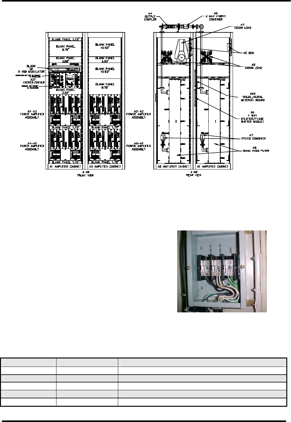
LX Series Power Amplifier Assembly Chapter 3, Site Considerations,
Installation and Setup Procedures
LX Series, Rev. 1 3-6
Figure 3-3. Front and Rear View 76” Cabinet Typical 4kW Configuration
Output Connections
Connect the transmission line for the
antenna system to the output of the
coupler assembly or the Bandpass Filter.
If the optional trap filter is present in
your system, a BNC sample jack is
located on the trap filter and can be used
for test purpose.
3.4 AC Input
Once the chassis and output connections
are in place, the AC can be connected to
the transmitter. The AC Input to the
high power transmitter connects to the
terminal block mounted in the AC input
box located toward the rear, right side
near the top of the cabinet. Connect the
AC Input Line 1 to Line 1 on the terminal
block, the AC Input Line 2 to Line 2 on
the terminal block and the AC Input
Ground to Ground on the terminal block.
Figure 3-4. AC Input Box Assembly.
Table 3-2: LX Series Transmitters AC Input and Current Requirements.
Transmitter Voltage Current
250 Watt 220 VAC 10 Amps to the Exciter/Amplifier Cabinet
500 Watt 220 VAC 15 Amps to the Exciter/Amplifier Cabinet
1000 Watt 220 VAC 25 Amps to the Exciter/Amplifier Cabinet
2000 Watt 220 VAC 45 Amps to the Exciter/Amplifier Cabinet
3000 Watt 220 VAC 65 Amps to the Exciter/Amplifier Cabinet

LX Series Power Amplifier Assembly Chapter 3, Site Considerations,
Installation and Setup Procedures
LX Series, Rev. 1 3-7
Transmitter Voltage Current
220 VAC 45 Amps to the Exciter/Amplifier Cabinet
4000 Watt 220 VAC 40 Amps to the Amplifier Cabinet
220 VAC 55 Amps to the Exciter/Amplifier Cabinet
5000 Watt 220 VAC 50 Amps to the Amplifier Cabinet
220 VAC 65 Amp to the Exciter/Amplifier Cabinet
6000 Watt 220 VAC 60 Amps to the Amplifier Cabinet
NOTES: Transmitters 4000 Watts and
above require two 220 VAC Inputs,
one to each cabinet.
All currents are with a Black picture.
When the AC is connected to the
terminal block in the AC input box,
the AC is directly connected to the
transmitter.
This completes the unpacking and
installation of the LX Series UHF
television transmitter. Refer to the setup
and operation procedures that follow
before applying power to the transmitter.
3.5 Setup and Operation
Initially, the transmitter should be turned
on with the RF output at the directional
coupler terminated into a dummy load of
at least the rated power of the
transmitter. If a load is not available,
check that the output of the directional
coupler is connected to the antenna for
your system.
3.5.1 Input Connections
The input connections to the transmitter
are to the rear of the exciter/driver
chassis assembly for the transmitter or to
the receiver tray in a translator.
NOTE: If the system contains two exciter
assemblies and an exciter switcher, then
the input connections must be made to
both exciter/driver assemblies.
Refer to the tables and description that
follows for detailed information on the
input connections.
NOTE: If both the Receiver and
Modulator are present in your system
the Modulated IF output from the
Receiver or Modulator must be selected.
This is accomplished by connecting a low
or removing the low to TB31-Pin 3
located on the rear of the exciter/driver
assembly. By connecting the low, the
Modulator IF output is used by the IF
Processor module. By removing the low,
the IF from the internal or external
Receiver is used.
(NOTE: The IF Processor board must be
configured for external switching by
placing jumper W11 on J29 between
pins 1 & 2. Normally, this is completed
at the factory).
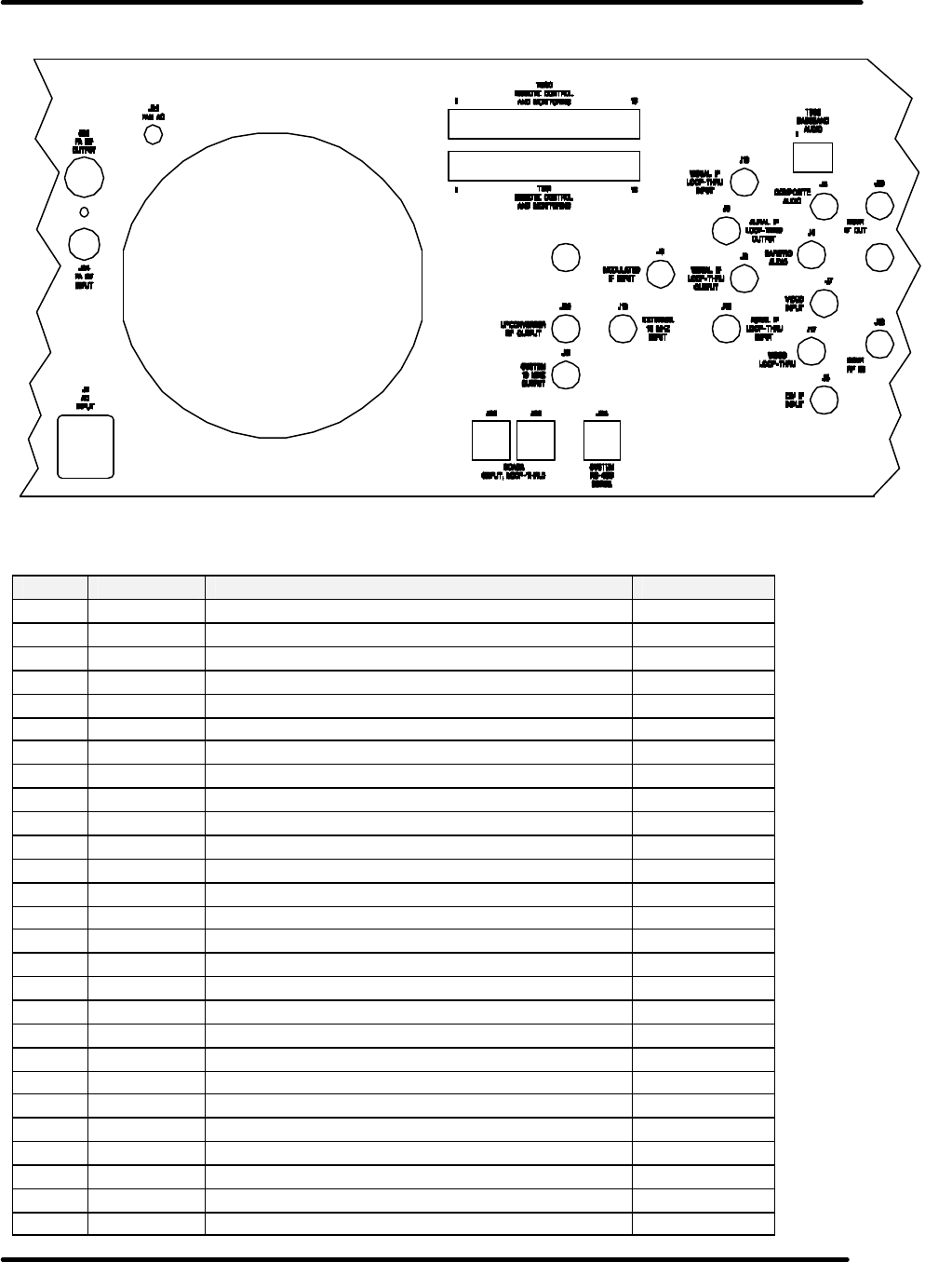
LX Series Power Amplifier Assembly Chapter 3, Site Considerations,
Installation and Setup Procedures
LX Series, Rev. 1 3-8
Figure 3-5: Rear View of LX Series Transmitter/Translator
Table 3-3: Rear Chassis Connections for the LX Series Transmitter.
Port Type Function Impedance
J1 IEC AC Input N/A
TB02 Term Base Band Audio Input 600O
J3 BNC Composite Audio Input 75O
J4 BNC SAP / PRO Audio Input 50O
J5 BNC CW IF Input 50O
J6 BNC Modulated IF Input 50O
J7 BNC Video Input (Isolated) 75O
J8 BNC Visual IF Loop-Thru Output 50O
J9 BNC Aural IF Loop-Thru Output 50O
J10 BNC External 10 MHz Reference Input 50O
J11 BNC System 10 MHz Reference Output 50O
J12 BNC Receiver RF Input 50O
J13 BNC Receiver IF Output 50O
J14 BNC RF Spare 2 50O
J15 BNC RF Spare 1 50O
J17 BNC Video Loop-Thru (Isolated) 75O
J18 BNC Visual IF Loop-Thru Input 50O
J19 BNC Aural IF Loop-Thru Input 50O
J23 BNC Upconverter RF Output 50O
J24 BNC Power Amplifier RF Input 50O
J25 N Power Amplifier RF Output 50O
TB30 Term Remote Control & Monitoring N/A
TB31 Term Remote Control & Monitoring N/A
J1
J24
J25
J21 TB30
TB31
J32
J34
J33
J11
J10
J23
J6
J5
J
19
J18
TB02
J3
J4
J7
J17
J8
J9
J12
J13
J14
SPARE
J15
SPARE

LX Series Power Amplifier Assembly Chapter 3, Site Considerations,
Installation and Setup Procedures
LX Series, Rev. 1 3-9
Port Type Function Impedance
J32 RJ-45 SCADA (Input / Loop-Thru) CAT5
J33 RJ-45 SCADA (Input / Loop-Thru) CAT5
J34 RJ-45 System RS-485 Serial CAT5
3.5.2 Initial Turn On
Once the unit has been installed and all
connections have been made, the
process of turning on the equipment can
begin. First verify that AC power is
present and connected to the
transmitter. Verify all cables are properly
connected and are the correct type.
Once all of these things are done, the
unit is ready to be turned on following
the procedures below.
NOTE: In systems with two exciters and
an exciter switcher; complete the
following procedure with Exciter A as the
On Air exciter, then repeat with Exciter B
as the On Air exciter. The exciter
switcher must in Manual.
Turn on the main AC power source that
supplies the AC to the transmitter. Check
that the AC power plug is connected to
J1 on the rear of the chassis assembly.
Monitor the LCD display located on the
front of the control/monitoring module
as you proceed through this section.
When the transmitter is in the operate
mode, the STB menu appears. When in
the standby mode, the OPR menu
appears. Press the NXT key after each
menu to continue through to the next
sequence.
3.5.2.1 (Optional) Receiver Module
LEDs on Front Panel
Fault Indicators:
PLL 1 FLT: This illuminates Red when
the Local Oscillator PLL is unlocked.
PLL 2 FLT: This illuminates Red when
the optional input frequency correcting
PLL is unlocked.
ALC FLT: This illuminates Red when the
ALC can not maintain output level.
Status Indicators:
DC ON I/P: This indicator will illuminate
Red when DC is applied to the RF input
center conductor.
MAN ALC: This illuminates Red when
the ALC can not maintain output level..
3.5.2.2 Modulator Module LEDs on
Front Panel
Fault Indicators:
AUR UNLOCK: This illuminates Red
when the Aural IF PLL is unlocked.
VIS UNLOCK: This illuminates RED
when the Visual IF PLL is unlocked.
AUD OV DEV: This indicator will
illuminate Red when the audio over-
deviates the aural carrier.
VIDEO LOSS: This indicates the loss of
Video to the modulator, when Red.
OVER MOD: This illuminates Red when
the video is over-modulated.
Status Indicators:
ALT IF CW: This indicates that there is
an external IF CW signal applied to the
Modulator
10MHz PRES: This indicates the
presence of a 10 MHz reference input.

LX Series Power Amplifier Assembly Chapter 3, Site Considerations,
Installation and Setup Procedures
LX Series, Rev. 1 3-10
3.5.2.3 IF Processor Module LEDs on
Front Panel
Fault Indicators:
INPUT FAULT: This illuminates Red if
the input to the module is missing or
low.
ALC FAULT: This illuminates RED when
the needed ALC value to maintain the
output level is beyond the range of the
circuitry.
MUTE: This indicator will illuminate Red
when the transmitter is muted.
3.5.2.4 VHF/UHF Upconverter Module
LEDs on Front Panel
Fault Indicators:
AGC FAULT: This illuminates Red if the
required gain to produce the desired
output level is beyond the value set by
the AGC circuit. AGC out of range.
AGC OVERRIDE: This illuminates Red if
the drive to the driver module is too
high.
MAN GAIN: This illuminates Red if the
AGC is bypassed in Manual.
PLL 1: This illuminates Red if the 1 GHz
PLL is unlocked.
PLL 2: This illuminates Red if the 1.1-
1.9 GHz PLL is unlocked.
3.5.2.5 Controller Module LEDs on
Front Panel
Status Indicators:
OPERATE: This illuminates Green when
transmitter is in operate.
FAULT: This illuminates Red when a
fault has occurred in the transmitter.
DC OK: This illuminates Green when the
DC outputs that connect to the modules
in the transmitter are present.
3.5.2.6 Power Amplifier or Driver
Module LEDs on Front Panel
NOTE: Both the PA Module and
Driver Module have the same front
panel LEDs.
Status Indicators:
ENABLED: This illuminates Green when
the PA is in operate.
DC OK: This illuminates Green when the
DC inputs to the PA module are present.
TEMP: This illuminates Green when the
temperature of the heatsink in the PA is
below 78°C.
MOD OK: This illuminates Green when
the PA module is operating and has no
faults.
If the Module OK LED is Red and blinking
a fault is present. The meaning of the
blinking LED is as follows.
1 Blink indicates Amplifier Current
Fault.
2 Blinks indicate Temperature Fault.
3 Blinks indicate +32V Power Supply
Over Voltage Fault.
4 Blinks indicate +32V Power Supply
Under Voltage Fault.
5 Blinks indicate Reflected Power Fault.
6 Blinks indicate +12V or –12V Power
Supply Fault
3.5.3 Front Panel Screens for the
(Optional) Exciter Switcher Tray in
Dual Exciter Systems
(Used in Dual Exciter Systems only)
The following screens are found on the 4
x 20 display located on the front of the
single channel exciter switcher tray.

LX Series Power Amplifier Assembly Chapter 3, Site Considerations,
Installation and Setup Procedures
LX Series, Rev. 1 3-11
Display Menu Screens for the (Optional) Exciter Switcher Tray
Table 3-4: Menu 01 - Splash Screen #1
This is the first of the two exciter switcher splash screens that is shown for the first few
seconds after reset or after pushing the SPL button on the Main Screen. Will
automatically switch to the second splash screen.
Table 3-5: Menu 02 - Splash Screen #2
This is the second of the two exciter switcher splash screens. Will automatically switch to
the Main Screen. The Name, Model Number, Code Version Number and Firmware
Number for your system are displayed on this screen. Make note of these two numbers
when conferring with Axcera on software problems.
Table 3-6: Menu 03 – Exciter Switcher Control Screen
This screen indicates that the exciter switcher is in automatic back-up and that Exciter A
is selected as the On Air Exciter. By selecting MANUAL the screen is shown as below.
Table 3-7: Menu 04 – Exciter Switcher Control Screen
This screen indicates that the exciter switcher is in Manual operation and that Exciter A is
selected as the On Air Exciter.
Table 3-8: Menu 05 – Exciter Switcher Control Screen
This screen indicates that there are 20 External Amplifiers reporting serial data in the
system. Also indicates that Exciter A is selected as the On Air Exciter and that the
system is in Manual, because the USE B option is present on the screen. By pushing the
button under USE B you are able to select Exciter B as the ON Air Exciter.
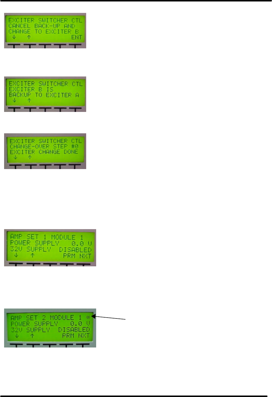
LX Series Power Amplifier Assembly Chapter 3, Site Considerations,
Installation and Setup Procedures
LX Series, Rev. 1 3-12
Table 3-9: Menu 06 – Exciter Switcher Control Screen
This screen allows you to cancel the automatic back-up and that Exciter B is selected as
the On Air Exciter.
Table 3-10: Menu 07 – Exciter Switcher Control Screen
This screen indicates that Exciter B is selected as Back up to the On Air Exciter A.
Table 3-11: Menu 08 – Exciter Switcher Control Screen
This screen is only displayed when an exciter back up sequence is initiated. The backup
sequence runs through 10 steps that are displayed on 10 different screens. 9) Exciter
A/B On, 8) Disabling Exciter A, 7) Disabling Exciter B, 6) Changing Relay 1 of 2, 5)
Changing Relay 2 of 2, 4) Waiting for Relays, 3) Relay Change Done, 2) Enabling Exciter
A, 1) Enabling Exciter B; 0) Exciter Change Done. If a problem occurs during the
sequence it will stop on the screen where the problem occurred.
Table 3-12: Menu 09 – External Amplifier Status
These screens indicate the Status of the different Amplifier Modules. This screen is
monitoring the power supply for Module 1 in Amplifier Set 1. By arrowing down, the next
parameter for that module is viewed and these screens will continue for each individual
module in each Amplifier Set.
Table 3-13: Menu 10 – External Amplifier Status with Serial Link Icon
Serial Link Icon
Indicates that this module is not
present in your System or the
module may be present but no serial
communication commands are being
received from the device.
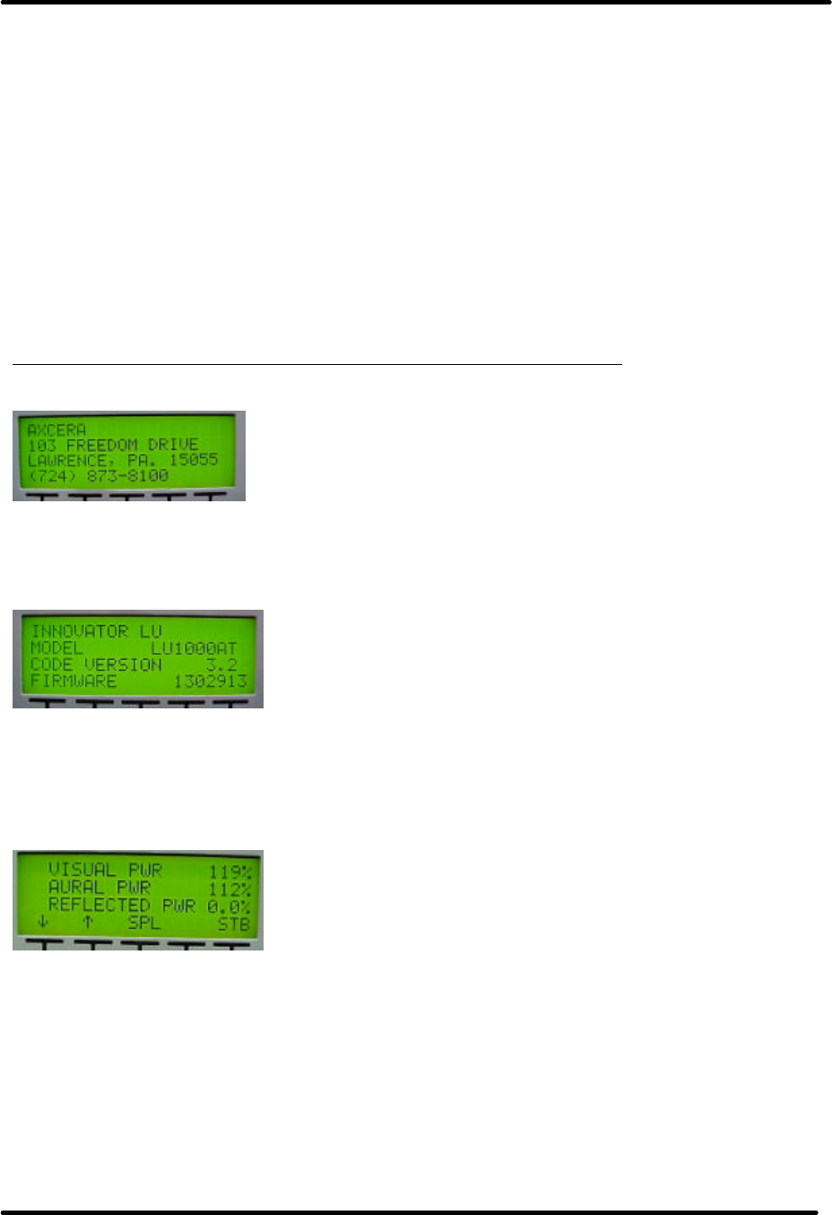
LX Series Power Amplifier Assembly Chapter 3, Site Considerations,
Installation and Setup Procedures
LX Series, Rev. 1 3-13
3.5.4 Front Panel Screens for the
Exciter/Amplifier Chassis Assembly
A 4 x 20 display located on the front of
the Control & Monitoring/Power Supply
Module is used in the LX Series
transmitter for control of the operation
and display of the operating parameters
of the transmitter. Below are the typical
display screens for the system and may
vary depending on your system. The ↑
and ↓ characters are special characters
used to navigate up or down through the
menu screens. Display text flashes on
discrete fault conditions for all screens
that display a fault condition. When the
transmitter is in operate mode, the STB
menu appears. When the transmitter is
in standby mode, the OPR menu
appears.
NOTE: In systems with two exciters and
an exciter switcher the following screens
appear on the exciter that is selected as
the On Air Exciter.
Display Menu Screens for the LX Series Transmitter/Translator
Table 3-14: Menu 01 - Splash Screen #1
This is the first of the two transmitter splash screens that is shown for the first few
seconds after reset or after pushing the SPL button on the Main Screen. Will
automatically switch to the second splash screen.
Table 3-15: Menu 02- Splash Screen #2
This is the second of the two transmitter splash screens. Will automatically switch to the
Main Screen. The Model Number, Code Version Number and Firmware Number for your
system are displayed on this screen. Make note of these two numbers when conferring
with Axcera on software problems.
Table 3-16: Menu 10 - Main Screen:
This is the default main screen of the transmitter. When the transmitter is in
operate, the 'STB' characters appear, allowing an operator to place the transmitter in
STANDBY, by pushing the right most button located under to display. When the
transmitter is in standby the 'STB' characters are replaced with 'OPR' and the forward
power values are displayed as OFF. An operator can change the transmitter from
STANDBY to OPERATE by pressing the right most button on the front panel display. If the
transmitter is in operate mode but off due to a modulation fault, the display reports the
system power as Auto Off. Pushing the SPL button will display the two splash screens.
If the ↓ key is activated the display changes to Menu 11, the System Error List Access
Screen. If the ↑ key is activated the display changes to Menu 13, the Transmitter
Configurations Access Screen.
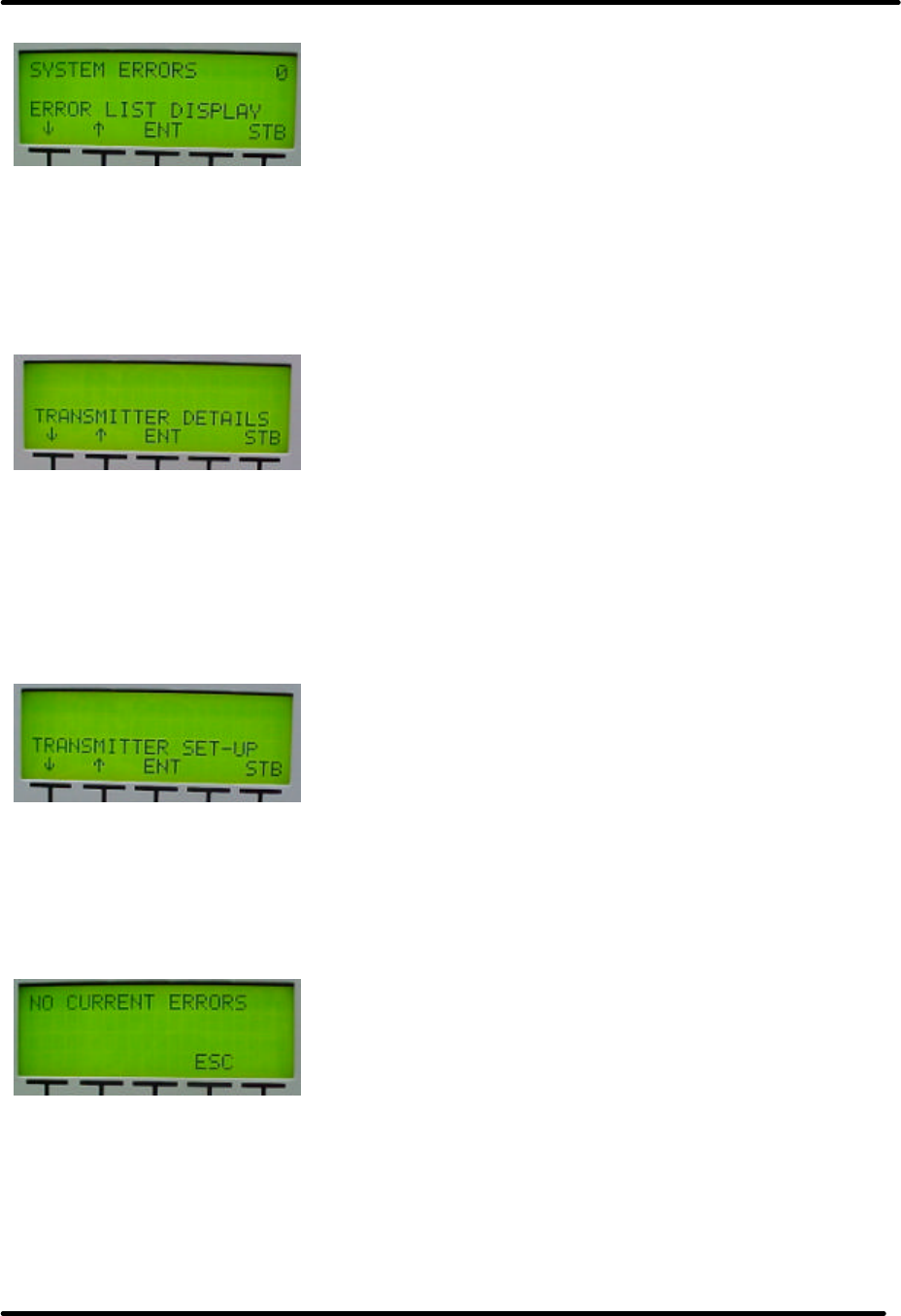
LX Series Power Amplifier Assembly Chapter 3, Site Considerations,
Installation and Setup Procedures
LX Series, Rev. 1 3-14
Table 3-17: Menu 11 - Error List Access Screen
This screen of the transmitter shows the current number of errors, displayed in upper,
right of screen (0), and provides operator access to view Menu 20, the error list screens,
by pushing the ENT button. When ENT is pushed, Menu 20, the Error List Display Screen
is displayed. If the ↓ key is pushed the display changes to Menu 12, Table 3-18, the
Transmitter Device Data Access Screen. If the ↑ key is activated the display returns to
Menu 10, the Main Screen.
Table 3-18: Menu 12 - Transmitter Device Data Access Screen
This screen of the transmitter allows access to various parameters of the transmitter
system. This is the entry point to Menu 30, the System Details Screens, by pausing the
ENT button. When the ENT button is pushed, Menu 30 is accessed. Go to Menu 30, Table
3-23 for set up details. Before pushing the ENT button: if the ↓ key is activated the
display changes to Menu 13, Transmitter Configurations Access Screen. If the ↑ key is
activated the display returns to Menu 11, the Error List Access Screen.
Table 3-19: Menu 13 - Transmitter Configuration Access Screen
This screen of the transmitter allows access to various software settings of the
transmitter system. If ENT is pushed, go to Menu 40, Table 3-24, the access to
transmitter configuration and set up. Before pushing the ENT button: if the ↓ key is
activated the display returns to Menu 10, Main Screen. If the ↑ key is activated the
display returns to Menu 12, the Transmitter Device Data Access Screen.
Table 3-20: Menu 20 - Error List Display Screen
This screen of the transmitter allows access to the system faults screens. Fault logging is
stored in non-volatile memory. The transmitter's operating state can not be changed in
this screen. The 'CLR' switch is used to clear previously detected faults that are no
longer active. The ↑ key and ↓ key allow an operator to scroll through the list of errors
that have occurred. The ESC button is used to leave this screen and return to Menu 11,
Table 3-17, the Error List Access Screen. NOTE: Shown is example of a typical screen.
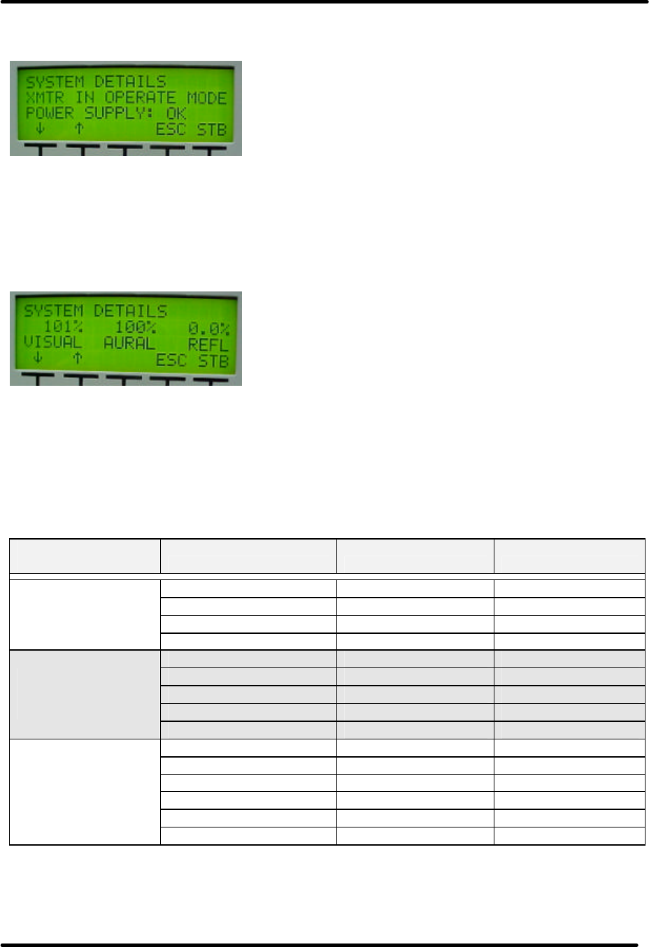
LX Series Power Amplifier Assembly Chapter 3, Site Considerations,
Installation and Setup Procedures
LX Series, Rev. 1 3-15
Menu 30 is entered by selecting ENT at Menu 12, Table 3-8.
Table 3-21: Menu 30 - Transmitter Device Details Screen
This screen allows access to the transmitter parameters of installed devices. The system
is configured to know which devices are present. Current values for all installed devices
are shown. If a module is not installed, only a "MODULE NOT PRESENT" message will be
displayed. The first screen displayed is Menu 30-1, Table 3-22, the System Details
Screen.
Table 3-22: Menu 30-1 – System Details Screen
The ↓ and ↑ arrows allow you to scroll through the different parameters of each device as
shown in Table 3-23. Each System Component is a different screen. The proper IF
Processor and the Driver or the Power Amplifier will be programmed for your system.
The External Amplifier Modules will only be used in high power transmitters. Examples of
External Amplifier Modules displays are: (AMP SET 1 MODULE 1) and (AMP SET 2
MODULE 4).
Table 3-23: Transmitter Device Parameters Detail Screens
System
Component Parameter Normal Faulted (Blinking)
AFC 1 LEVEL 0 - 10.00 V N/A
PLL 1 CIRCUIT LOCKED UNLOCKED
ALC INPUT OK FAULT
Receiver Details
(Not used with
transmitter.) FAULT AT 0 - 10.00 V FAULT
PLL CIRCUIT LOCKED UNLOCKED
OUTPUT LEVEL .24 – 1.00 V N/A
AURAL DEVIATION 0 - 125 kHz N/A
CW INPUT PRESENT NOT USED
Modulator Details
(May Not be used
with receiver.) CALL SIGN NONE N/A
INPUT SIGNAL STATE OK FAULT
MODULATION OK FAULT
INPUT IF MODULATOR or J6 N/A
DLC CONTROL LOCK 0 - 5.00 V N/A
ALC LEVEL 0 - 5.00 V N/A
IF Processor
Details
ALC MODE AUTO or MANUAL N/A
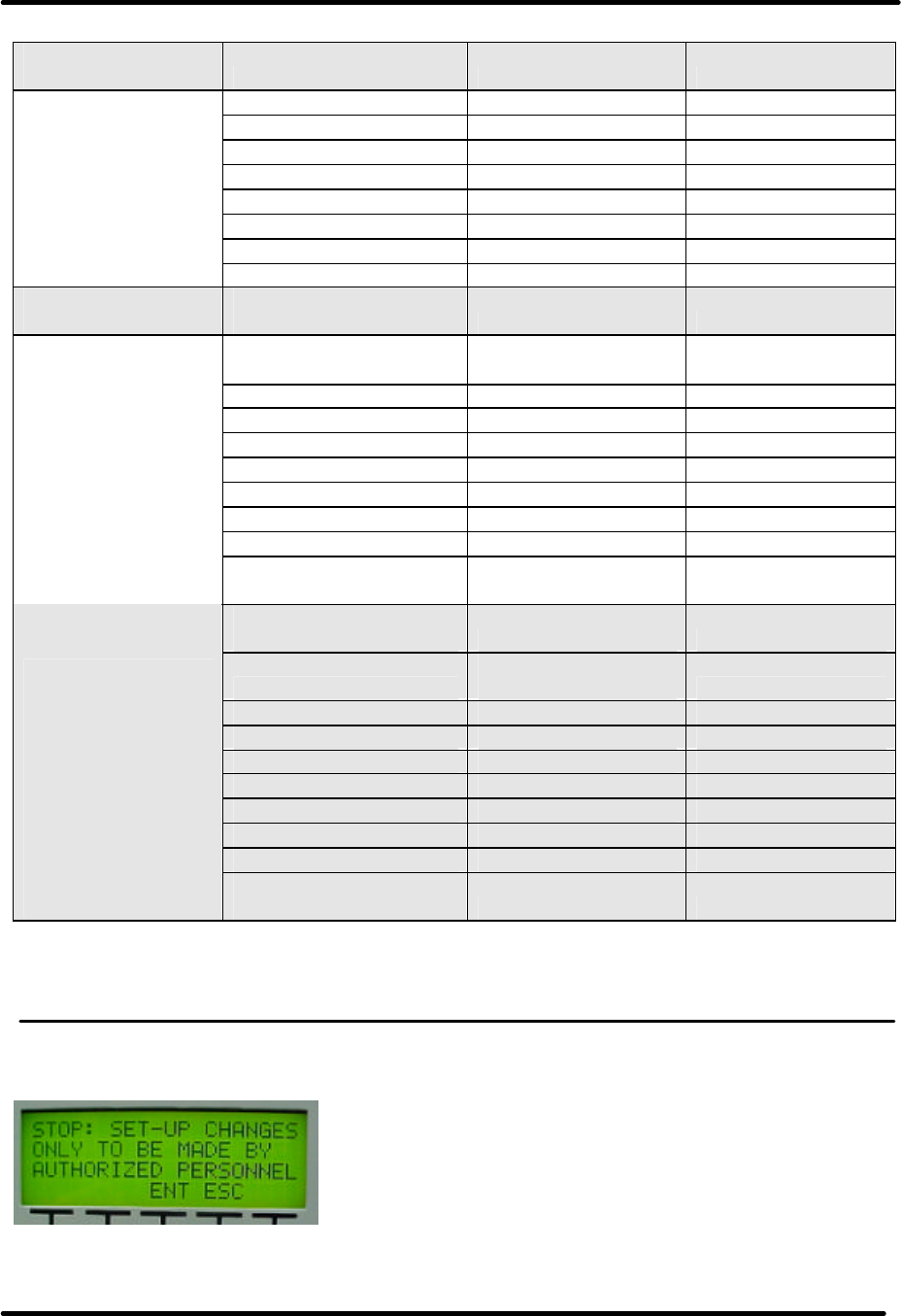
LX Series Power Amplifier Assembly Chapter 3, Site Considerations,
Installation and Setup Procedures
LX Series, Rev. 1 3-16
System
Component Parameter Normal Faulted (Blinking)
AFC 1 LEVEL 0 – 5.00 V N/A
AFC 2 LEVEL 0 - 5.00 V N/A
CODE VERSION x.x N/A
PLL 1 CIRCUIT LOCKED FAULT
PLL 2 CIRCUIT LOCKED FAULT
AGC 1 LEVEL 0 - 5.00 V N/A
AGC 2 LEVEL 0 - 5.00 V N/A
Upconverter
Details
INT. 10 MHz IS USED N/A
System Control
Details SUPPLY ENABLED
FOR xxx HOURS N/A
POWER SUPPLY
STATE, 32V 32 VDC N/A
±12V SUPPLY OK or OFF FAULT
FORWARD POWER xxx% xxx%
REFLECTED POWER xxx% xxx%
AMP 1 CURRENT xx.xA xx.xA
AMP 2 CURRENT xx.xA xx.xA
TEMPERATURE xxC xxC
CODE VERSION x.x N/A
Driver and PA
Details
PA HAS OPERATED
FOR xxx HOURS N/A
POWER SUPPLY
VOLTAGE, 32V 31 – 32 VDC N/A
32V SUPPLY ENABLED or
DISABLED FAULT
FORWARD POWER xxx% xxx%
REFLECTED POWER xxx% xxx%
AMP CURRENT 1 xx.xA xx.xA
AMP CURRENT 2 xx.xA xx.xA
AMP CURRENT 3 xx.xA xx.xA
AMP TEMPERATURE xxC xxC
CODE VERSION x.x N/A
Ext. Power
Amplifier Modules
Details (Only in
high power
systems).
Will indicate Amp
Set and Module
within the Set.
Will step through
each Set and
Module. PA HAS OPERATED
FOR xxx HOURS N/A
Pushing the ↓ Down Arrow, after scrolling through all the detail screens, will put you back
to Menu 30, Table 3-21. Push the ESC button to exit the Transmitter Device Parameter
Screens to Menu 12, Table 3-18 to the Transmitter Device Parameter Access Screen.
Menu 40 (Table 3-24) is entered by selecting ENT at Menu 13.
Table 3-24: Menu 40 - Authorized Personnel Screen
This screen of the transmitter notifies an operator that they are only to proceed if they
are authorized to make changes to the transmitter's operation. Changes made within the

LX Series Power Amplifier Assembly Chapter 3, Site Considerations,
Installation and Setup Procedures
LX Series, Rev. 1 3-17
following set-up screens can affect the transmitters output power level, output frequency,
and the general behavior of the transmitter. Please do not make changes within the
transmitter's set-up screens unless you are familiar with the operation of the transmitter.
This screen is implemented in transmitter software version 1.4 and above.
Pressing ENT will put you into the Transmitter Set Up Screens for Menu 40.
A safeguard is added to the Set Up Menus in software version 2.5 and above. If a change
is made to a screen within the Set Up Menus, when you go to the next menu, a new
screen asks if you accept the change or want to return to the previous menu to
reconsider the changes made.
To accept the changes, the two buttons located under ACCEPT must be pushed
simultaneously.
To return to the previous Menu to make corrections, the two buttons located under the
RETURN must be pushed simultaneously.
Upon returning to the previous Menu the correct input must be entered and the above
procedure repeated, this time accepting the changes
Accept or Return to previous Menu Screen
Pushing these two buttons Pushing these two buttons
Simultaneously will accept Simultaneously will return you
the change. to the previous Menu.
The Set Up Screens are shown in Table 3-25 Menu 40-1 through Table 3-42 Menu 40-18
that follow.
Table 3-25: Menu 40-1 - Transmitter Set-up: Power Control Screen
This screen of the transmitter is the first of several that allows access to transmitter set-
up parameters. When + is selected, the Power will increase. When - is selected, the
Power will decrease.
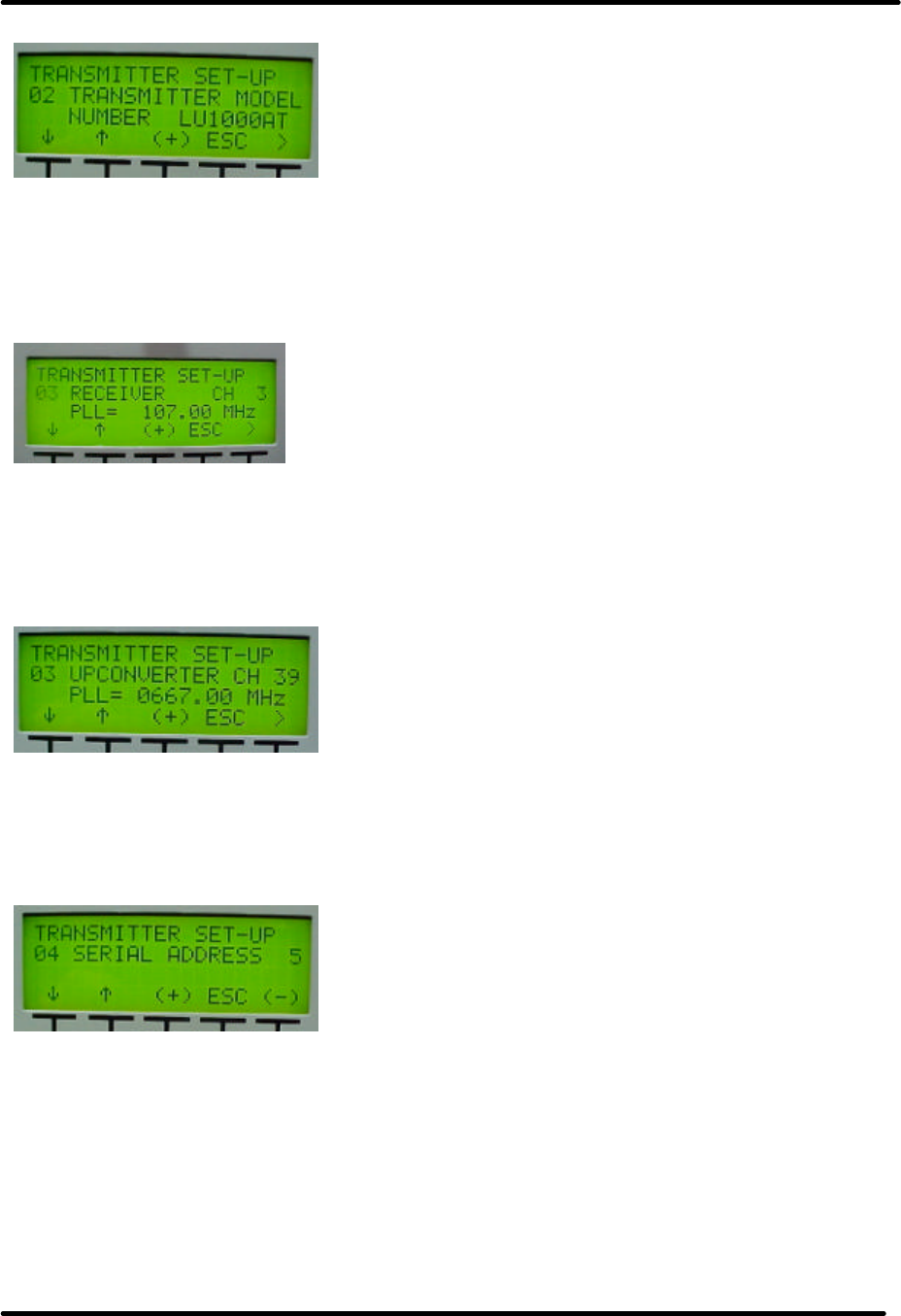
LX Series Power Amplifier Assembly Chapter 3, Site Considerations,
Installation and Setup Procedures
LX Series, Rev. 1 3-18
Table 3-26: Menu 40-2 - Transmitter Set-up: Model Select Screen
This screen is used to specify which components are expected to be part of the system.
By specifying the model number, the transmitter control firmware knows which
components should be installed and it will be able to display faults for components that
are not properly responding to system commands.
Table 3-27: Menu 40-3 - Transmitter Set-up: Receiver Channel Configuration
This screen of the transmitter allows access to transmitter frequency set-up parameters.
The choices of this screen are as follow. NOTE: The above screen will only be present if a
Receiver is part of the system. Used to set the Receiver Channel designation and for
custom Channel Offsets the setting of the PLL operating frequency.
Table 3-28: Menu 40-4 - Transmitter Set-up: Upconverter Channel Select Screen
The choices of this screen are to the standard UHF / VHF channels. The + and – buttons
change the desired channel of the transmitter. The PLL frequency is set for custom
Offsets within the upconverter frequency. Any change to the channel is immediately set
to the LO / Upconverter Frequency Synthesizer PLL circuit.
Table 3-29: Menu 40-5 - Transmitter Set-up: Serial Address Screen
This screen allows the user to set the serial address of the transmitter. The default
address is 5. This value and all other set-up parameters, are stored in non-volatile
memory.
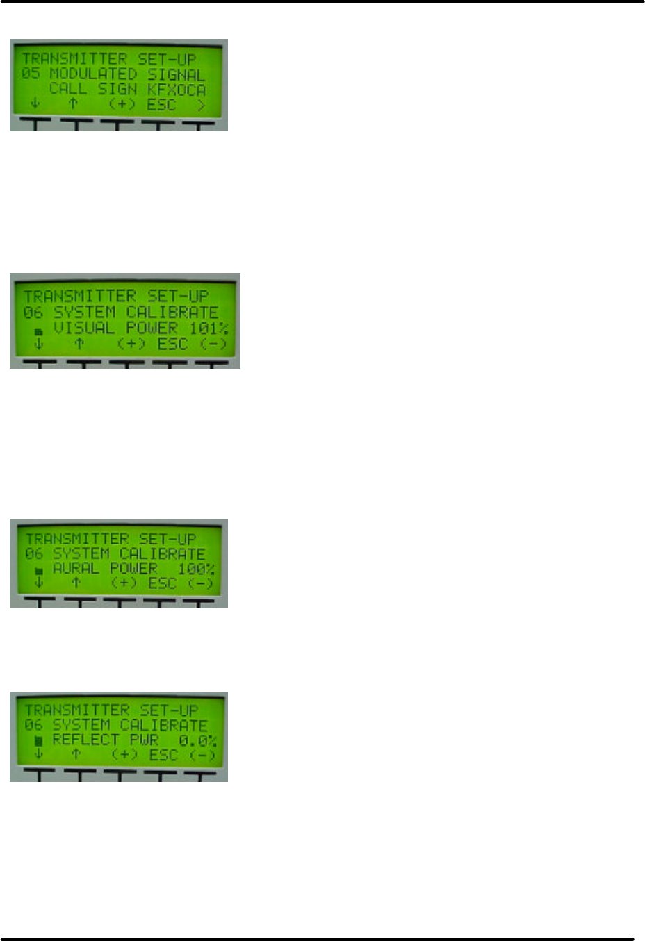
LX Series Power Amplifier Assembly Chapter 3, Site Considerations,
Installation and Setup Procedures
LX Series, Rev. 1 3-19
Table 3-30: Menu 40-6 - Transmitter Set-up: Station ID Screen
This screen allows the user to set the Station ID, Call Sign, in analog transmitters. If
blank characters are used for all five positions, then the Station ID feature is disabled.
Otherwise the Station ID code is transmitted every 15 minutes. This value and all other
set-up parameters, are stored in non-volatile memory. (NOTE: If an external Receiver
Tray is used in your system, the LX Series Station ID is disabled. Therefore, the Station
ID must be set up in the external Receiver Tray.)
Table 3-31: Menu 40-7 - Transmitter Set-up: System Visual Power Calibration
This screen is used to adjust the calibration of the system's visual power. A symbol
placed under the '6' character is used to show major changes in the calibration value.
When the calibration value is at full value, the character will be full black. As the value
decreases, the character pixels are gradually turned off. The calibration value is a value
between 0 and 255 but the calibration value symbol only has 40 pixels. Therefore small
changes in actual calibration value may not affect the symbol's appearance.
Table 3-32: Menu 40-8 - Transmitter Set-up: System Aural Power Calibration
This screen is used to adjust the calibration of the system's aural forward power. A
calibration value symbol is used for this screen as on the previous screen.
Table 3-33: Menu 40-9 - Transmitter Set-up: System Reflected Power Calibration
This screen is used to adjust the calibration of the system's reflected power. Again a
calibration value symbol is used for this screen as on the previous screens.

LX Series Power Amplifier Assembly Chapter 3, Site Considerations,
Installation and Setup Procedures
LX Series, Rev. 1 3-20
Table 3-34: Menu 40-10 - Transmitter Set-up: Modulated Output Calibration
In analog systems this screen is used to adjust the calibration of the system's modulated
output signal detector. The calibration value symbol is again used to graphically
represent the modulated output signal detector's calibration value.
Table 3-35: Menu 40-11 - Transmitter Set-up: Aural Deviation Calibration
In analog systems this screen is used to adjust the calibration of the system's aural
deviation detector. The calibration value symbol is again used to graphically represent
the aural deviation detector's calibration value.
Table 3-36: Menu 40-12 - Transmitter Set-up: Forward Power Fault Threshold Screen
This screen is used to set the minimum forward power fault threshold. When the
transmitter is operating, it must operate above this value otherwise the system will shut
down with fault for 5 minutes. If after five minutes the fault is not fixed, the transmitter
will enable, measure power less than this value and again shut down for five minutes.
Table 3-37: Menu 40-13 - Transmitter Set-up: Reflected Power Fault Threshold
This screen is used to set the maximum reflected power fault threshold. When the
transmitter is operating, it must not operate above this value otherwise the system will
slowly begin to reduce the forward output power. If the system's reflected output power
exceeds the maximum reflected power threshold by five percent or more, the transmitter
will shut down with fault for 5 minutes. If after five minutes the fault is not fixed, the
transmitter will enable, measure power above this value plus five percent and again shut
down for five minutes. If the system's reflected output power exceeds the maximum
reflected power threshold due to some condition like the formation of ice on an antenna,
the transmitter reduces forward power to a level where the reflected power is less than
this threshold. The transmitter will automatically increase its output power to normal
operation when the cause of higher than normal reflected power is corrected.

LX Series Power Amplifier Assembly Chapter 3, Site Considerations,
Installation and Setup Procedures
LX Series, Rev. 1 3-21
Table 3-38: Menu 40-14 - Transmitter Set-up: Auto Stand-By Control
Certain LX transmitter locations are required to reduce to no output power on the loss of
video input. When a LX transmitter is configured for Auto Stand-By On Modulation Loss,
the transmitter will switch to stand-by, if a modulated input signal fault is detected by the
IF Processor module that lasts for more than ten seconds. Once the modulated input
signal fault is cleared, a transmitter in operate mode will return to normal operation. This
feature is implemented in transmitter software version 1.4 and above.
Table 3-39: Menu 40-15 - Transmitter Set-up: Receiver ALC Fault Set Up
This screen is used to set up the level of the ALC at which the Receiver will fault. This
feature is implemented in transmitter software version 2.0 and above. NOTE: The above
screen will only be present if a Receiver is part of the system.
Table 3-40: Menu 40-16 - Transmitter Set-up: Inner Loop Gain Control
This screen is used to set up the Inner Loop Gain of the exciter/amplifier assembly. This
feature is implemented in transmitter software version 2.0 and above
Table 3-41: Menu 40-17 - Transmitter Set-up: Optional System Control
This screen is used to set up any optional system, including the addition of the optional
Modulator in a translator system. This feature is implemented in transmitter software
version 2.0 and above.

LX Series Power Amplifier Assembly Chapter 3, Site Considerations,
Installation and Setup Procedures
LX Series, Rev. 1 3-22
Table 3-43: Menu 40-19 - Transmitter Set-up: Remote Commands Control
This screen is used to allow or deny the use of remote control commands. When
disabled, remote commands are not used. Remote commands are commands received
either through the rear terminal blocks or through serial messages.
Push the ESC button to exit the Transmitter Set Up Screens to Menu 13, Table 3-19, the
Transmitter Configuration Access Screen.
This completes the description of the menu screens for the LX Series exciter/amplifier
chassis assembly.
3.5.5 Operation Procedure
If necessary, connect the transmitter to
the antenna. Check that the output is
100% and if needed, adjust the ALC
Gain adjust pot on the front panel of
the IF Processor to attain 100%. The
power raise / lower settings, in the
menus, are only to be used for
temporary reductions in power. The
power set-back values do not directly
correspond to the power of the
transmitter. Setting for 50% output
sets a linear circuit voltage that is
controlling a non-linear power circuit.
(NOTE: For digital transmitters only)
NOTE: In systems with two exciters
and an exciter switcher, repeat the
proceeding procedure with Exciter B as
the On Air exciter. The exciter
switcher must in Manual.
This completes the Installation, Set Up
and Turn On of the Transmitter.
If a problem occurred during the setup
and operation procedures, refer to
Chapter 5, Detailed Alignment
Procedures, of this manual for more
information.

LX Series Power Amplifier Assembly Chapter 4, Circuit Descriptions
LX Series, Rev. 1 4-1
Chapter 4
Circuit Descriptions
Power Amplifier Chassis Assembly
The RF from the exciter/driver assembly
connects from the RF Output “N” Jack J25,
through a RG-55 cable, to the PA RF Input
“N” Jack J200 or J201, located on the rear
of the PA chassis assembly. In systems
with multiple Power Amplifier Assemblies,
the RF output from the exciter/driver is
split and then fed to each of the PA RF
Input Jacks. In systems with two exciters
and an exciter switch the RF outputs from
the exciter/drivers are connected to the
exciter switcher then the selected exciter
output is either connected directly to the
PA RF Input “N” Jack J200 or J201,
located on the rear of the PA chassis
assembly or is split and then fed to each
of the PA RF Input Jacks.
The RF Input to the PA assembly is wired
through UT-141 cable to the OSP port
J111, J121, J131 or J141 on the PA
chassis assembly, one for each 250W PA
module slide in assembly. Jack J1 on the
250W PA module assembly connects to
the OSP port when the module assembly
is slid into the PA slot. In the 250W PA
module, the RF is amplified and connected
to the PA RF Output Jack or J2, located on
the rear of the PA Module assembly. Jack
J2 on the PA module connects to the J112,
J122, J132 or J142 port, on the main
chassis assembly, when the module
assembly is slid into place. In a 250W
system the output at J12 connects directly
to J203 the 7/16” Jack that is located on
the rear of the PA chassis assembly.
The RF outputs of the PA module
assemblies are combined in a 2 way
combiner in a 500 Watt system or in a 4
way combiner in a 1 kW system. The RF
output jack of the PA chassis assembly is
the output of the combiner at the 7/16”
Jack J205 that is located on the rear of
the PA chassis assembly.
4.1 (A4) Power Amplifier Module
Assembly
The Power Amplifier Module Assembly
contains (A1) a UHF Phase/Gain Board
(1303213), (A2) a 150W Driver Pallet,
Dual Output (1303293), (A3 & A4) UHF RF
Module Pallet Assemblies (1300116), (A5)
a 2 Way UHF Combiner Assembly
(1303208), (A6) an Amplifier Control
Board (1303682, 1301962 or 1303702)
and (A7) a Temperature Sensor IC.
4.1.1 (A1) UHF Phase/Gain Board
(1303213; Appendix B)
The RF input from J1 on the PA assembly
connects to J1 on the Phase/Gain Board.
The UHF phase/gain board provides the
circuits that adjust the gain and the phase
of the RF signal for the PA amplifier
assembly in which it is mounted. The input
signal connects to the gain circuit through
the capacitor C13. The gain circuit consists
of U1, R16, CR4, R22, R17, CR5, R23, R27
and the gain pot, R25. U1 is a 90°, 2-way
splitter. The signal at pin 1 of U1 is split
and applied to pins 3 and 4. The signal
reflects off CR4 and CR5 and is passed to
pin 2. The gain between pins 1 and 2
changes with the voltage applied across
CR4 and CR5. This voltage is controlled by
the gain-adjust pot R25. The more
positive the voltage, the more the diodes
CR4 and CR5 conduct therefore the less
gain through the circuit. The gain
controlled output is coupled through C14
and the pi-type divider circuit consisting of
R8, R5 and R9 that drops the level before it
applied to the phase-shifter circuit.
The level controlled signal connects to the
phase-shifter circuit that consists of U2,
C20, C21, CR2, and CR3. U2 is a 90°, 2-
way splitter. The signal at pin 1 of U2 is
split and applied to pins 3 and 4. The signal
reflects off CR2 and CR3 and is passed to
pin 2. The phase shift between pins 1 and
2 changes with the voltage applied across

LX Series Power Amplifier Assembly Chapter 4, Circuit Descriptions
LX Series, Rev. 1 4-2
CR2 and CR3. This voltage is controlled
by the phase-adjust pot R24 through
R26, R18 and R19. +12 VDC from an
external switching power supply is
applied to J3 on the board and is used as
the reference that is applied to the
phase-control pot. The gain and phase
controlled output connects to J2 on the
board.
4.1.2 (A2) 150 Watt Driver Pallet
Assembly, Dual Output (1303293;
Appendix B)
The output of the Phase/Gain Board is
connected to the input J1 of (A2) the 150
Watt UHF amplifier assembly. The
assembly contains a 150 Watt CW UHF
Driver Board, Dual Output (1303169).
4.1.3 150 Watt Driver, Dual Output
(1303169; Appendix B)
The board operates class AB and is a
highly linear broadband amplifier for the
frequency range of 470 to 860 MHz. It
can deliver an output power of 150
watts (CW) with approximately 14 dB of
gain.
The amplification circuit consists of
LDMOS transistors Q1 and Q2 connected
in parallel and operating class AB. The
paralleling network is achieved with the
aid of 3 dB couplers U3 and U4. The
quiescent current settings are achieved
by means of potentiometers R6 and
R10. C39 and C38 are adjusted for best
response. The settings are factory
implemented and should not be altered.
PIN diode VR1 is a variable-damping
circuit that is used to adjust the
amplification of the module. The
adjustment is performed with the Gain
potentiometers R10 and R6. A
readjustment of the amplification may be
required, after repair work, to ensure that
the PAs in multiple PA transmitters deliver
the same output power.
4.1.4 (A3 & A4) UHF Module
Assembly, RF Module Pallet, Philips
(1300116;Appendix B)
The UHF Module Assembly, 250-watt
module (Figure 4-1) is a broadband
amplifier for the frequency range 470 to
860 MHz. The amplifier is capable of
delivering an output power of 70 Wrms.
The amplification is approximately 13 dB.
The amplification circuit consists of the
parallel connected push-pull amplifier
blocks V1 and V2 operating in class AB. In
order to match the transistor impedance
to the characteristic impedance of the
input and output sides, matching networks
are placed ahead and behind the amplifier
blocks. Transformers Z3 to Z6 serve to
balance the input and output signals. The
paralleling circuit is achieved with the aid
of 3-dB couplers Z1 and Z2.
The working point setting is factory
implemented by means of potentiometers
R9, R11, and R12 and should not be
altered.
V 1
3 dB Coupler
Z 2
RF
Output
RF
Input 3 dB Coupler
Z 1
R 2
R 1
Matching
Network
Matching
Network
V 2
Matching
Network
Matching
Network
Z 3 Z 5
Z 4 Z 6
+Uop
N 1
R 11 R 12
R 9
R 10 Dynamic
Equalization
Figure 4-1. UHF Amplifier Module, 250 Watts

LX Series Power Amplifier Assembly Chapter 4, Circuit Descriptions
LX Series, Rev. 1 4-3
4.1.5 (A5) 2 Way UHF Combiner
Assembly (1303208; Appendix B)
The 2 Way UHF combiner board assembly
combines the two outputs of the UHF
Module Assemblies and also provides
forward and reflected power samples of
the output to (A6) the amplifier control
board where it connects to the input of
the overdrive-protection circuit.
The RF inputs to the 2 way UHF combiner
assembly, from the UHF amplifier
modules, are soldered to the external
connection points J3 and J4. The RF is
combined by the stripline tracks and R5 a
100O matching resistor across the two
inputs, to the RF Output solder
connection point at J5. A hybrid-coupler
circuit picks off a power sample that is
connected to SMA type connector jack J1
as the forward power sample. Another
power sample is taken from the coupler
circuit that is connected to SMA type
connector jack J2 as the reflected power
sample. Two 50O terminations, created
from two 100O resistors in parallel, used
as dissipation loads, connect from the
forward and reflected ports to ground.
4.1.6 (A5) Amplifier Control Board
1303682, 1301962 or 1303702;
Appendix B)
The amplifier control board provides LED
fault and enable indications on the front
panel of the module and also performs
the following functions: overdrive
cutback, when the drive level reaches the
amount needed to attain 110% output
power; and overtemperature, VSWR, and
overdrive faults. The board also provides
connections to the LCD Display for
monitoring the % Reflected Power, %
Output Power, and the power supply
voltage
If the Module OK LED on the front panel
is Red and blinking a fault is present.
The meaning of the blinking LED is as
follows.
1 Blink indicates Amplifier Current Fault.
2 Blinks indicate Temperature Fault.
3 Blinks indicate +32V Power Supply
Over Voltage Fault.
4 Blinks indicate +32V Power Supply
Under Voltage Fault.
5 Blinks indicate Reflected Power Fault.
6 Blinks indicate +12V or –12V Power
Supply Fault
Page 1
U4, located upper center of page, is an in
circuit microcontroller. The controller is
operated at the frequency of 3.6864 MHz
using crystal Y1. Programming of this
device is performed through the serial
programming port J2. U4 selects the
desired analog channel of U1 through the
settings of PA0-PA3. The outputs of Port A
must be set and not changed during an
analog input read of channels PA5-PA7.
PA4 of U4 is a processor operating LED
that monitors the +/-12 VDC. PA5 is used
to monitor the +12VDC supply to the
board. PA6 is the selected channel of
analog switch U1. PA7 is connected to a
via, V10, for future access.
U6 is a serial to RS-485 driver IC. U7 is a
watchdog IC used to hold the
microprocessor in reset, if the supply
voltage is less than 4.21 VDC. U7
momentarily resets the microcontroller if
Pin 6 (!ST) is not clocked every second. A
manual reset switch is provided but should
not be needed. Located in the Upper left
corner, U3 is used to determine where the
amplifier control board is located. The
eight inputs come from the main amp
connector and are used to set the SCADA
address of the controller. Pull-up resistors
set a default condition of logic high.
U5 below U3 is used for getting digital
input information of the board. Page two
has several monitoring circuits that provide
information on the amplifier’s status. Many
of these circuits automatically shut down
the amplifier if a specific fault occurs.
U8 below U5 is used to control four board
mounted status LEDs. A FET is turned On

LX Series Power Amplifier Assembly Chapter 4, Circuit Descriptions
LX Series, Rev. 1 4-4
to shunt current away from the LED to
turn it Off. U9 below U8 is used to
enable different features within the
software. Actual use is to be determined.
Page 2
In the lower right corner are voltage
regulator circuits. U22 should allow for
0.14 amps of power using its 92 C/W
rating if Ta = 60°C max and Tj = 125°C
max 0.26 amps can be obtained from
U22 if the mounting pad is 0.5 square
inches. The controller will not need this
much current.
U23 and U24 are low drop out +5 VDC,
voltage regulators with a tolerance
greater than or equal to 1%. 100mA of
current is available from each device but
again the controller will not need this
much current.
In the upper left section are circuits with
U12 and U13. U12 is used to generate a
regulated voltage that is about 5 volts
less than the +32 VDC supply,
approximately +26.25 VDC. When the
+32 VDC supply is enabled, the circuitry
around U13B is used to provide gate
voltage to Q10 that is 5 volts greater
than the source pin of this FET. The gate
of Q10 can be turned Off by any one of a
few different circuits.
U10A is used to turn Off the gate of Q10
in the event of high current in amplifier
#1. At 0.886 VDC the current to
amplifier #1 should be greater than 5
Amps. U11B is used to turn off the Q10
FET, if high current is detected in
amplifier #2. U11A is used to turn off
the Q10 FET, if high current is detected
in amplifier #3. With 2.257 VDC at Pin 5
of U11B or Pin 3 of U11A, the voltage
output of current sense amplifier U17 or
U18 at high current shut down should be
greater than 15 Amps.
U14B is used to turn Off the gate of Q10
in the event of high power supply
voltage, approximately +35.4 VDC.
U14A is used to keep the FET disabled in
the event of low power supply voltage,
approximately +25.4 VDC.
Current monitoring sections of the board.
The ICs U16, U17 and U18 along with
associated components set up the current
monitoring sections of the board. R67,
R68 and R69 are 0.01O/5W 1% through
hole resistor is used for monitoring the
current through several sections of the
amplifier. The voltage developed across
these resistors are amplified for current
monitoring by U16, U17 or U18. The
LT1787HVCS8 precision high side current
sense IC amplifier accepts a maximum
voltage of 60 VDC. The 43.2 kO resistor
from pin 5 to ground sets the gain of the
amplifier to about 17.28. This value is not
set with much accuracy since the
manufacturer internally matches the
resistors of this part but their actual
resistance value is not closely defined. A
trimming resistor is suggested to give a
temperature stability of –200 ppm/C, but
instead the microcontroller will determine
the exact gain of the circuit and use a
correction factor for measurements.
Circuit loading components are located in
the lower portion of each current
monitoring circuit. These components
allow for short duration high current
loading of the supply. By measuring the
current through the sense resistor with and
without the additional four 30.1 O 1%
resistors. For very short duration pulses, a
1206 resistor can handle up to 60 watts.
The processor requires 226 uSec per
conversion. A supply voltage of +32 VDC
will pass 1.06 amps + 1% through the load
resistors.
A6 is a temperature sensor thermistor
that is used to monitor the temperature of
the module's heat sink. It connects to J6
pins 1 & 2 on the board and is wired to
the comparator IC U10B. If the
temperature increases above 75°C the
output will go Low that is used as a
temperature fault output, which generates
a Fault alert at U15A and disables
Amplifier #1.

LX Series Power Amplifier Assembly Chapter 4, Circuit Descriptions
LX Series, Rev. 1 4-5
Aural, Visual/Average and Reflected
power detector sections of the board.
Page 3
A Forward Power Sample enters the
board at SMA Jack J3 and is split. One
part connects to J4 on the board that is
cabled to J1, the SMA Forward Power
Sample Jack, located on the front panel
of the assembly. The other part of the
split forward power sample is detected by
CR17 and the DC level amplified by
U25A. The output of U25A at pin 1 is
split with one part connected to the Aural
Power sample, which is not used in this
digital transmitter. The other split output
connects to U265A that is part of the
Forward Average Power circuit. The
detected level is connected to L4 that is
part of an intercarrier notch filter circuit
that is tuned to eliminate the 4.5 MHz
aural intercarrier, if present. The
Average power sample is amplified by
U26D and connected through the
average calibration pot R166 to U26C.
The output of U26C is connected to the
comparator IC U26B that has Aural Null
and Offset Null, if present in the system,
connected to the other input. The output
Average Forward power level connects to
J9 pin 2 of the board.
A Reflected Power Sample enters the
board at SMA Jack J5 and is detected by
CR20 and the DC level amplified by
U28B. The output of U28B at pin 7 is
connected through the reflected
calibration pot R163 to U28C. The
output is split with one part connected to
J9 pin 5, the Reflected Power Output
level of the board. The other part of the
split from U28C connects to the
comparator IC U28D that has a reference
level connected to the other input. If the
reflected level increases above the
reference level a low output is produced
and connected to the Reflected Power
Shutdown circuit at CR28. The low shuts
off Q14 causing pin 3 to go high that is
connected to the inverter U15C. The
output of U15C goes low producing a
Reflected Power Fault that is connected to
an output of the board, the Fault Alert
circuit and also shuts down Amplifier #1.
Gain of the power measurements is
completed through software. Only the
Aural Null and Offset Null need to be done
through front panel pots.
4.2 Power Supply Assembly (1302863;
Appendix B)
The Power Supply Assembly contains (A1)
a +32V/2000W switching power supply
(1301504) and (A2) a ±12V/40W
switching power supply (1303242). The
+32VDC connects through J1 (+32VDC)
and J2 (RTN) to the rest of the amplifier
assembly. The +/-12VDC outputs, the
+32VDC control lines and the 220VAC
connect to the assembly through Jack J3.
Each Power Supply Assembly supplies
voltages to two power amplifier
assemblies.
This completes the description of the Power
Amplifier Chassis Assembly, the Power
Amplifier Module Assembly and the Power
Supply Assembly.

LX Series Power Amplifier Assembly Chapter 5,Detailed Alignment Procedures
LX Series, Rev. 1 5-1
Chapter 5
Detailed Alignment Procedures
This Power Amplifier Assembly along with
the transmitter was aligned at the factory
and should not require additional
adjustments to achieve normal operation.
This transmitter takes the baseband
audio and video inputs and converts
them to the desired UHF On Channel RF
Output at the systems output power
level.
The Power Amplifier Assembly of the
Innovator LX Series transmitter is of a
Modular design and when a Module fails
that module needs to be changed out
with a replacement module. The failed
module can then be sent back to Axcera
for repair. Contact Axcera Customer
Service Department at 724-873-8100 or
fax to 724-873-8105, before sending in
any module.
5.1 Module Replacement
Module replacement on the LX Series
products is a relatively simple process.
The power supply and power amplifier
modules, plug into a blind mating
connector located on the chassis. To
replace a module, refer to the following
procedure.
Loosen the two grip lock connectors,
located on the front panel, at the top
and bottom of the module,
counterclockwise until the module
releases.
NOTE: To remove the driver/power
amplifier module, mounted in the
exciter/driver assembly, the input and
output cables must be removed from the
rear of the module and also a 6/32” x ½”
Philips screw, mounted between the two
connectors, needs to be removed before
the module will pull out. After removal of
the screw, which is used to hold the
module in place during shipping, it does
not need to be replaced.
NOTE: To remove the Combiner Module,
found in the power amplifier assembly in
high power transmitters, the output cable
must be removed from the rear of the
module and also two 8/32” x ½” Philips
screws, mounted above the connector,
need to be removed before the module
will pull out. After removal of the screws,
which are used to hold the module in
place during shipping, they do not need
to be replaced.
After removal of the failed module, slide
the replacement module in place and
make certain it connects to the blind
mate connector. Replace the two cables
on the rear of the PA chassis assembly.
If the replacement module does not
slide in easily, verify it is properly
aligned in the nylon tracks, located on
both the top and bottom of the module.
Note: Each Module has an assigned slot
and will not fit properly in the incorrect
slot. Do not try to place a Module in the
wrong slot as this may damage the slot
or the blind mate connectors.
5.1.1 Initial Test Set Up
Check that the RF output at the coupler
is terminated into a dummy load of at
least the rated output of the system.
While performing the alignment, refer to
the Test Data Sheet for the transmitter
and compare the final readings from the
factory with the readings on each of the
modules. The readings should be very
similar. If a reading is way off, the
problem is likely to be in that module.
Switch On the main AC for the system.
5.2 Innovator LX Series
Exciter/Driver Chassis Assembly
This transmitter operates using the
baseband audio and video inputs.

LX Series Power Amplifier Assembly Chapter 5,Detailed Alignment Procedures
LX Series, Rev. 1 5-2
NOTE: In systems that contain two
exciters with an exciter switcher, both
exciters must have audio and video
inputs. Each exciter should be operated
one at a time using the following
procedure by first selecting Exciter A as
the On Air exciter then selecting Exciter B
as the On Air exciter. The Exciter
Switcher must be in the manual mode.
On the LCD Display, located on the
Controller/Power Supply Module, in
Transmitter Set-Up, push the right
button to switch the transmitter to
Operate, STB will be displayed.
The check of and the setup of the Audio
and Video input levels are completed
using the LCD Display and the front panel
adjustments on the Modulator assembly.
The level of the RF output includes
adjustments of the drive level to the
Power Amplifier and the adjustment of
the linearity and phase predistortion to
compensate for any nonlinear response
of the Power Amplifier. The adjustments
are located on the front panel of the IF
Processor module.
5.2.1 (Optional) Receiver Module
Assembly
NOTE: Not present in a Transmitter
system.
Connect an on channel RF input to J12
the receiver RF input jack on the rear of
exciter/driver assembly. Verify that all
LEDs located on the front panel of the
Receiver are Green. The following details
the meaning of each LED:
PLL 1 Fault (DS6) - Displays the status
of the Local oscillator PLL
PLL 2 Fault (DS8) - Displays status of
optional input frequency correcting PLL
DC on center conductor (DS4) -
Displays whether or not DC is applied to
the RF input center conductor*
*Caution: Do not hook up the RF
input to any test equipment with the
DC bias applied. Always move the
jumper W1 on J2 on the UHF
Preamplifier board to the Bias off
position, between pins 2 & 3, to
prevent possible damage to the test
equipment.
5.2.2 Modulator Module Assembly
NOTE: The Modulator Assembly may not
be present in a translator system.
The Modulator Assembly has adjustments
for video levels and audio modulation
levels, and other related parameters.
Connect an NTSC baseband video test
signal input (1 Vpk-pk) to the transmitter
video input jack J7 on the rear of the
tray. Jacks J7 and J17 are loop-through
connected; the J17 jack can be used as a
video source for another transmitter.
Connect a baseband audio input (+10
dBm) to the balanced audio input
terminal block TB02-1 [+], TB02-2 [-],
and TB02-3 [ground] or, if
stereo/composite audio is provided,
connect it to BNC jack J3, the composite
audio input jack.
Verify that all LEDs located on the front
panel of the Modulator are Green. The
following details the meaning of each
LED:
AURAL UNLOCK (DS5) – Red Indicates
that 4.5 MHz Aural IF is unlocked from
the 45.75 MHz visual IF.
VISUAL UNLOCK (DS6) – Red Indicates
that the 45.75 MHz visual IF is unlocked
from the 10 MHz reference.
AUDIO OVER DEVIATION (DS4) – Red
Indicates that the input Audio level is too
high.
VIDEO LOSS (DS1) – Red Indicates that
the input Video level is too low.
OVER MODULATION (DS3) – Red
Indicates that the input Video level is too
high.

LX Series Power Amplifier Assembly Chapter 5,Detailed Alignment Procedures
LX Series, Rev. 1 5-3
ALTERNATE IF (DS7) – Red Indicates
that an external 45.75 MHz IF is not
present to the modulator.
10 MHz PRESENT (DS2) – Red Indicates
that an external 10 MHz reference in not
present to the modulator.
Look at the front panel LCD meter on the
Control/Power Supply Module Assembly.
Set the LCD screen to the Modulator
Details video output level screen, the
screen indicates active video from 0 to 1
Vpk-pk. The normal video input level is 1
Vpk-pk on the front panel screen. If this
reading is not at the proper level, the
overall video level can be changed by
adjusting the VIDEO LEVEL control R42
on the front panel of the Modulator to the
1 Vpk-pk level on the front panel screen.
Switch the LCD display to the Modulator
Details screen that indicates the AUDIO
DEVIATION (modulation level) of the
signal from 0 to 100 kHz.
MONO SET UP: The modulator was
factory set for a ±25-kHz deviation with
a mono, balanced, audio input of +10
dBm. If the reading is not at the correct
level, adjust the MONO Audio Gain pot
R110, located on the front panel of the
modulator, as necessary, to attain the
±25-kHz deviation on the front panel
screen.
STEREO SET UP: The modulator was
factory set for a ±75-kHz deviation with
a stereo, composite, audio input of 1
Vpk-pk. If this reading is not correct,
adjust the STEREO Audio Gain pot R132,
located on the front panel of the
modulator, as necessary, for the ±75-
kHz deviation.
SECONDARY AUDIO SET UP: NOTE:
Remove any stereo or mono audio
modulation input to the transmitter
during the set up of the secondary audio.
The modulator was factory set for a ±15-
kHz deviation with a secondary audio
input of 1 Vpk-pk. If this reading is not
correct, adjust the SAP/PRO Audio Gain
pot R150, located on the front panel of
the modulator, as necessary, for the
±15-kHz deviation.
5.2.3 IF Processor Module Assembly
Verify that all red LEDs located on the IF
Processor front panel are extinguished.
The following details the meaning of each
LED when illuminated:
• DS1 (input fault) – Indicates that
either abnormally low or no IF is
present at the input of the IF
Processor module.
• DS2 (ALC fault) – Indicates that the
ALC circuit is unable to maintain the
signal level requested by the ALC
reference. This is normally due to
excessive attenuation in the linearity
signal path or the IF phase corrector
signal path, or that switch SW1 is in
the Manual ALC Gain position.
• DS4 (Mute) – Indicates that a Mute
command is present to the system.
Switch the transmitter to Standby. The
ALC is muted when the transmitter is in
Standby.
5.2.4 VHF/UHF Upconverter Module
Assembly
Switch the transmitter to Operate. Verify
that all LEDs located on the front panel of
the Upconverter are Green. The following
details the meaning of each LED:
PLL 1 Fault (DS1) - Displays the status
of the 1 GHz PLL, Green locked or Red
unlocked
PLL 2 Fault (DS2) - Displays status of
the 1.1-1.9 GHz PLL, Green locked or
Red unlocked
AGC Fault (DS7) - Displays status of
AGC, Green normal or Red out of range
AGC Override (DS3) - Displays status
of AGC cutback, either Green normal
drive level, no cutback, or too much

LX Series Power Amplifier Assembly Chapter 5,Detailed Alignment Procedures
LX Series, Rev. 1 5-4
drive level to driver module, Red
cutback.
Manual Gain (DS6) - Displays status of
the control of the AGC level, either
Green normal, AGC Adj. using R6 or
Amber manual, Man Gain Adj. using R7.
5.2.5 Setting Up the Drive Level of
the Transmitter Procedure
Setting the Manual AGC
Preset the front panel “Man Gain” pot on
the Upconverter full Counterclockwise,
and the Man/Auto Gain Switch to the
Left, Man.
NOTE: The MAN/AUTO switch on this
upconverter is the opposite polarity to
the switch on the old upconverters for
the LX transmitter.
Turn the transmitter to Operate, and
slowly adjust the Man Gain pot until the
desired % output power, as read on the
LCD display, has been reached. The
Manual AGC is now set. Normal
operation of the Transmitter is in the
Auto AGC position.
Setting the Auto AGC
With the transmitter in Standby, preset
the AGC pot on the Upconverter full
Counterclockwise. Preset the AGC
Cutback pot on the Upconverter full
Clockwise. Move the Man/Auto Gain
Switch on the Upconverter to the Right,
Auto. Switch the transmitter to
Operate and slowly adjust the AGC pot
until the desired output power has been
reached.
Monitor the output of the transmitter
with a Spectrum Analyzer and turn the
power up 1 dB higher than desired using
the AGC pot. Enter the Transmitter Set-
Up menu on the LCD Control Panel and
step through the screens until the
screen labeled “Inner Loop Gain” is
reached. The inner loop is adjustable
from 0-255. Use the + button to
increase the Inner Loop Gain until the
power on the spectrum analyzer just
begins to decrease. Use the – button to
decrease the inner loop gain by 10%. (If
it begins to affect power at setting 160,
drop it back down to 160-16=144, if it
affects power at 100, drop it down by 10
to 90, etc….).
Slowly turn the AGC Cutback Pot
Counterclockwise until the AGC
Override light begins to flicker, and the
output power begins to drop. Turn the
pot Clockwise slightly, so the light just
goes out and the power stabilizes. Turn
the AGC pot down to get back to the
desired % output power level. The Auto
AGC is now set. Normal operation of the
Transmitter is in the Auto AGC position.
5.2.6 Changing the Transmitter
Channel Procedure
Place the transmitter in Standby and go
to the Set Up Menu, Transmitter
Configuration Access Screen, on the LCD
Display. Step through the screens until
the screen labeled “Upconverter CH xx”
is reached, where xx is the current
channel that the upconverter is on. The
channel number should be blinking. To
change the channel, hit the + button to
step through the channels until the
desired channel is reached.
To select a 10kHz offset to the channel
frequency, use the > button to move
the curser to the LO frequency listed
below the Channel number, and keep
pressing the > button until the desired
digit is blinking, and then use the +
button to change the frequency.
Example:
Nominal LO frequency for Channel 14 =
0517.00 MHz. To generate a + offset,
change the LO frequency to 0517.01
MHz. To generate a – offset, change the
LO frequency to 0516.99 MHz.
5.2.7 Frequency Response Delay
Equalization Adjustment
The procedure for performing a
frequency response delay equalization

LX Series Power Amplifier Assembly Chapter 5,Detailed Alignment Procedures
LX Series, Rev. 1 5-5
adjustment for the transmitter is
described in the following steps:
The center frequency for the first stage is
45 MHz. Adjust R103, the top frequency
response equalizer pot, located on the
front panel of the IF Processor Module,
for the best depth of frequency response
correction at 45 MHz.
The center frequency for the second
stage is 43.5 MHz. Adjust R106, the
middle frequency response equalizer pot,
located on the front panel of the IF
Processor Module, for the best depth of
frequency response correction at 43.5
MHz.
The center frequency for the third stage
is 42 MHz. Adjust R274, the bottom
frequency response equalizer pot, located
on the front panel of the IF Processor
Module, for the best depth of frequency
response correction at 42 MHz.
After the three delay attenuation
equalizers have been adjusted, fine tune,
as needed, for the best frequency
response across the channel.
NOTE: The frequency response
adjustment is done at IF, so the
frequency cut-in points will be reversed
at the UHF frequencies.
5.2.8 Linearity Correction
Adjustment
As shipped, the exciter was preset to
include amplitude and phase pre-
distortion.
The pre-distortion was adjusted to
approximately compensate the
corresponding non-linear distortions of
the Power Amplifier.
NOTE: On the IF processor board inside
the module, the correction enable/disable
jumper W12 on J30 will be in the Enable
position, on pins 2 & 3.
Set up a spectrum analyzer with 100
kHz resolution bandwidth and 100 kHz
video bandwidth to monitor the
intermodulation products of the RF
output signal of the Power Amplifier.
A typical red field spectrum is shown in
Figure 5-1. There are three Linearity
Corrector stage adjustments located on
the front panel of the IF Processor
Module. The adjustments are threshold
settings that are adjusted as needed to
correct for any amplitude or phase
intermod problems. Adjust the top
linearity correction adjustment R211
threshold cut in for the in phase
amplitude distortion pre-correction that
is needed. Next adjust the middle
linearity correction adjustment R216
threshold cut in also for the in phase
amplitude distortion pre-correction that
is needed. Finally adjust the bottom
linearity correction adjustment R231
threshold cut in for the quadrature
phase distortion pre-correction that is
needed. The above pots are adjusted
for the greatest separation between the
peak visual carrier and the
intermodulation products.
Figure 5-1. Typical Red Field Spectrum

LX Series Power Amplifier Assembly Chapter 5,Detailed Alignment Procedures
LX Series, Rev. 1 5-6
5.3 Bandpass Filter
NOTE: If your system contains a
Teracom manufactured tunable filter
assembly, refer to the manufacturers
manual included with the filter for
instructions on tuning and ignore the
following sections on the Axcera
manufactured Bandpass and Trap Filter
Assemblies.
NOTE: The bandpass filter and the
(optional) trap filter are factory swept
and should not be tuned without the
proper equipment. Do not attempt to
tune the filters without a sweep
generator or, preferably, a network
analyzer. If tuning is required, consult
with the Axcera Field Support
Department before attempting to tune
the filters.
The input to the bandpass filter is the
output of the Power Amplifier or the
hybrid combiner. The filter is made of
aluminum waveguide and has five
resonant cavities. The filter has five bolts
for tuning adjustments, three located in
the middle on the left and two on the
right, and four or six rods on the front of
the bandpass filter, depending upon the
channel, for coupling adjustments
between the sections. The bandpass filter
also utilizes two integral traps at -4.5
MHz and +9 MHz from FV at the top and
bottom, respectively, of the left-hand
side of the bandpass filter, looking from
the rear of the cabinet. Figure 5-2 shows
the location of the bolts used for making
tuning adjustments.
To tune the filter, connect a sweep signal
to the input of the filter and adjust the
five tuning bolts for a 6-MHz bandwidth
and a flat-frequency response across the
desired band.
NOTE: The bandpass ripple should be
≤0.25 dB. The 6-MHz band should also
have a minimum of 20 dB return loss
across the pass band.
See Table 5-1 for typical bandpass
values.
Table 5-1. Typical Bandpass Values
FREQUENCY INSERTION LOSS (dB) RETURN LOSS (dB)
FV-4.5 ≥ 35
FV-0.5 ≥ 20
FV ≤ 0.6 ≥ 20
Fa ≤ 0.6 ≥ 20
FV+8.08 ≥ 15
FV-9 ≥ 30
2FV ≥ 30
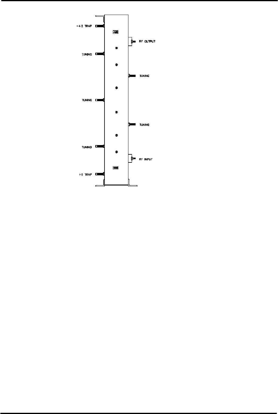
LX Series Power Amplifier Assembly Chapter 5,Detailed Alignment Procedures
LX Series, Rev. 1 5-7
Figure 5-2. Bandpass Filter
5.4 (Optional) One- or Two-Section
Trap Filter
The trap sections in the one- or two-
section trap filter have been factory
tuned and should not need major
adjustments. The trap filter is optional
and may not be part of this system.
The input to the one- or two-section trap
filter is the output of the bandpass filter.
The trap filter is comprised of 3-1/8" EIA
standard transmission line sections
connected to the main transmission line.
The transmission line assembly consists
of 7/8" EIA standard rigid coaxial
components.
The traps on the output trap filter are
labeled with their center frequency
relative to the frequency of the carrier
(for example, the traps labeled -4.5 MHz
are tuned for a center frequency of 4.5
MHz lower than the frequency of the
visual carrier).
The trap sections are reflective notches
and can be adjusted across the entire
UHF frequency band. The electrical length
of the outer sleeve and the center rod of
the notch can be adjusted to tune the
notch frequency. The depth of the notch
is set by the gap between the center
conductor of the trap section and the
center conductor of the main line. Tight
coupling makes a deep notch, while loose
coupling makes a shallow notch. A one-
section trap filter is shown in Figure 5-3.
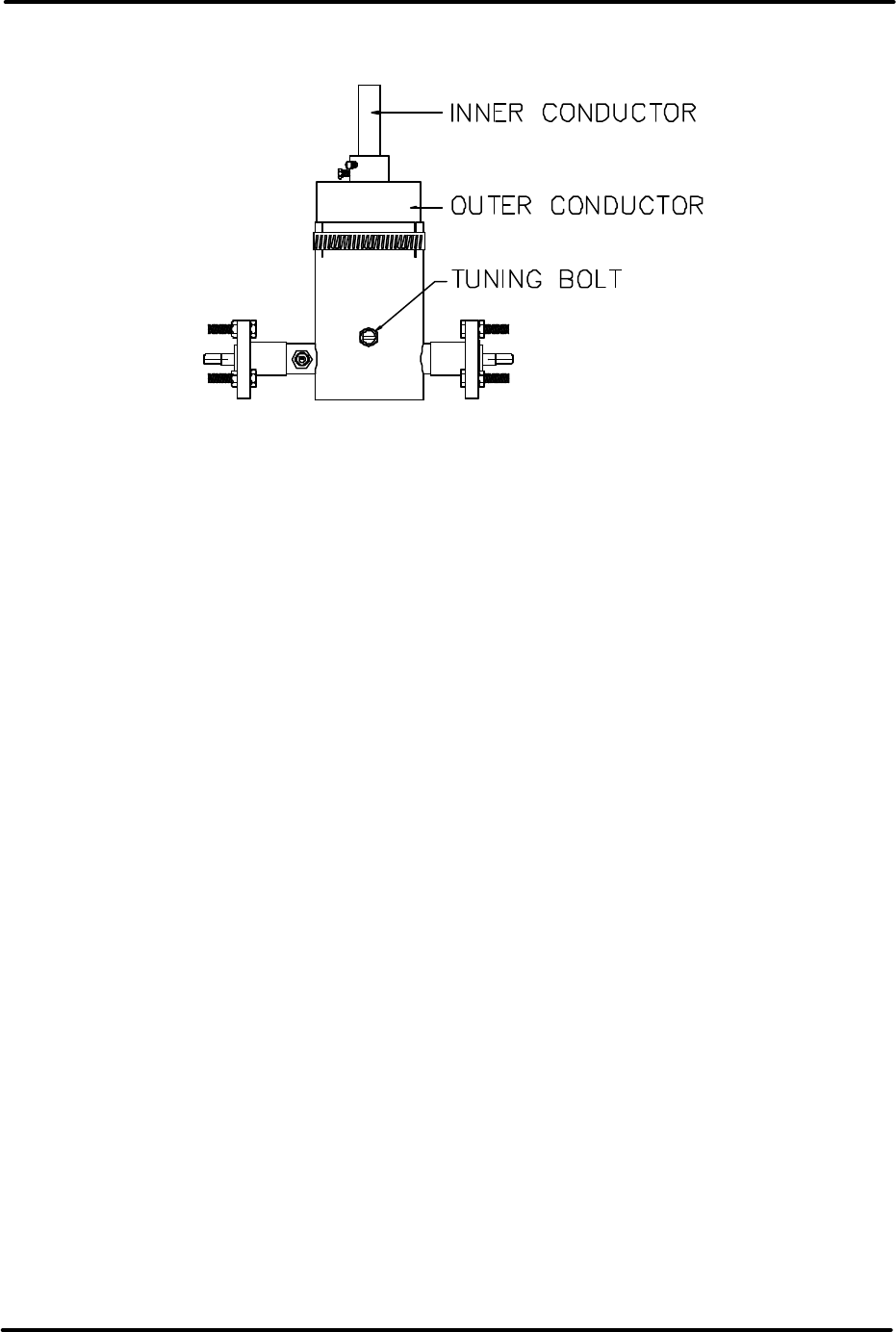
LX Series Power Amplifier Assembly Chapter 5,Detailed Alignment Procedures
LX Series, Rev. 1 5-8
Figure 5-3. One-Section Trap Filter
5.4.1 Fine Tuning
Fine tuning of the center frequency of the
notches can be accomplished with the
tuning bolts on the side of the filter
section. Loosen the nut that locks the
bolt in place and adjust the bolt to
change the frequency of the notch.
Monitor the output of the transmitter
with a spectrum analyzer and null the
distortion product with the bolt. Red field
is a good video test signal to use in order
to see the +8.08-MHz product. Tighten
the nut when the tuning is completed.
Hold the bolt in place with a screwdriver
as the nut is tightened to prevent the
bolt from slipping.
5.4.2 Major Tuning
For major tuning, such as changing the
notch depth or moving the notch
frequency more than 1 MHz, the outer
conductor and the center conductor of
the trap section must both be moved. An
RF sweep generator is required to
perform major tuning. Apply the sweep
signal to the input of the trap filter and
monitor the output. Loosen the clamp
holding the outer conductor in place and
lengthen the conductor to lower the
frequency of the notch or shorten it to
raise the frequency of the notch. Loosen
the center conductor with an Allen
wrench and move it deeper for a lower-
frequency notch or out for a higher-
frequency notch. These adjustments
must both be made to change the notch
frequency. Moving only the center
conductor or the outer conductor will
effect the notch depth and the center
frequency. The variable that is being
adjusted with this procedure is the length
of the center conductor inside the trap
filter. The gap between the trap and the
main line should not be changed. Moving
only the inner or the outer conductors
will effect the gap and the notch depth.
To only affect the notch depth, both
sections have to be moved. The notch
depth is controlled by the gap between
the center conductor and the trap
section. This gap also has an effect on
the center frequency. To deepen the
notch, shorten the outer conductor and
pull out the center conductor until the
notch is back in the same place. Move
the sections in the opposite direction to
make a shallow notch.
NOTE: The trap filter is typically adjusted
for a notch depth of 10 dB.
The results of tuning the output trap filter
are described in Table 5-2.

LX Series Power Amplifier Assembly Chapter 5,Detailed Alignment Procedures
LX Series, Rev. 1 5-9
Table 5-2. Results of Tuning the Output Trap Filter
TUNING ADJUSTMENT RESULT
Lengthening outer conductor only Notch frequency up, shallower notch
Shortening outer conductor only Notch frequency down, deeper notch
Inserting inner conductor deeper Notch frequency down, deeper notch
Inserting less inner conductor Notch frequency up, shallower notch
Tuning bolt in Notch frequency down
Tuning bolt out Notch frequency up
Moving both inner and outer conductors
to keep the same gap inside Center frequency moves, notch stays the
same
After the tuning has been completed,
tighten the clamp and the Allen screws
that hold the conductors. Use the fine-
tuning bolts to bring in the frequency.
The final tuning adjustments should be
completed with the transmitter driving
the output trap filter for at least one hour
to allow for warm-up drift.
5.5 Calibration of the Transmitter
Forward Output Power Level
NOTE: Perform the following procedure
only if the power calibration is suspect.
Switch the transmitter to Standby and
preset R51, the aural null pot on (A4) the
visual/aural metering board, fully CCW.
Switch the LO/Upconverter sled to
Manual Gain. Adjust R48, the null offset
pot on the visual/aural metering board,
full CW. Adjust CCW until 0% visual
output is displayed on the LCD Display in
the System Visual Power position.
Perform the following adjustments with
no aural present by removing the jumper
cable, the aural IF loop-through, that is
connected on the rear of the
exciter/driver chassis. Connect a sync
and black test signal to the video input
jack of the exciter/driver. Switch the
transmitter to Operate.
Next, set up the transmitter for the
appropriate average output power level
using the Manual Gain pot on the
LO/Upconverter sled:
Example is for a 1000 Watt transmitter.
• Sync + black 0 IRE
setup/wattmeter=595 watts
• Sync + black 7.5 IRE
setup/wattmeter=545 watts
NOTE: The transmitter must have 40 IRE
units of sync.
Adjust R28, visual calibration, on the
(A4) visual/aural metering board for .8V,
at TB30-14 and TB30-12 return, on the
exciter/driver assembly, then adjust
display to read 100% on the front panel
meter in the System Forward Power
position.
With the spectrum analyzer set to zero
span mode, obtain a peak reference on
the screen. Reconnect jumper cable on
the rear of the exciter/driver. While in
the Visual Output Power position, adjust
L3 for a minimum visual power reading
on the LCD display. Turn the power
adjust pot on the LO/Upconverter sled
front panel until the original peak
reference level is attained. Peak L1 and
C8 for a maximum aural power reading,
then adjust R20 for .8V, at TB30-15 and
TB30-12 return, on the exciter/driver
assembly, then adjust LCD display for
100% system aural power reading.
Switch to the Visual Output Power
position and adjust R51 for 100% visual
power on system LCD display.

LX Series Power Amplifier Assembly Chapter 5,Detailed Alignment Procedures
LX Series, Rev. 1 5-10
5.6 Calibration of the Transmitter
Reflected Output Level
On the meter, in the Visual Power
position, turn the power adjust pot to
25%. Move the Reflected cable on the
(A11) coupler to the unused “INC” port
on the coupler. Then adjust R39 on (A4)
the visual/aural metering board for a
.2VDC, at TB30-13 and TB30-12 return,
on the exciter/driver assembly. Then
adjust the LED display for 25% reading in
the System Reflected Power position. At
this 25% reference power reading a
reflected power fault should appear on
the System Errors Menu. Turn the power
adjust pot slightly CCW and the fault
should be clearable on the System Error
Menu. Turn the pot CW until the Fault
appears. The reflected output power is
now calibrated.
Switch the transmitter to Standby and
move the Reflected power cable on the
A11 Coupler back to the “Reflected Port”.
Switch the transmitter to Operate and
adjust the front panel power pot for a
100% visual power reading. Switch the
LO/Upconverter to the Auto AGC position
and adjust the ALC Gain adjust pot on
the front of the IF Processor module for
100% visual power reading, if needed.
The Transmitter is ready for normal
operation.
NOTE: In Dual Exciter Systems, with an
exciter switcher, repeat the above
procedure with Exciter B selected as the
On Air Exciter. The exciter switcher
must be in manual.
This completes the detailed alignment
procedures for the LX Series transmitter.
If a problem occurred during the
alignment, help can be found by calling
Axcera field support at 724-873-8100.
APPENDIX A
LX SERIES
SYSTEM SPECIFICATIONS
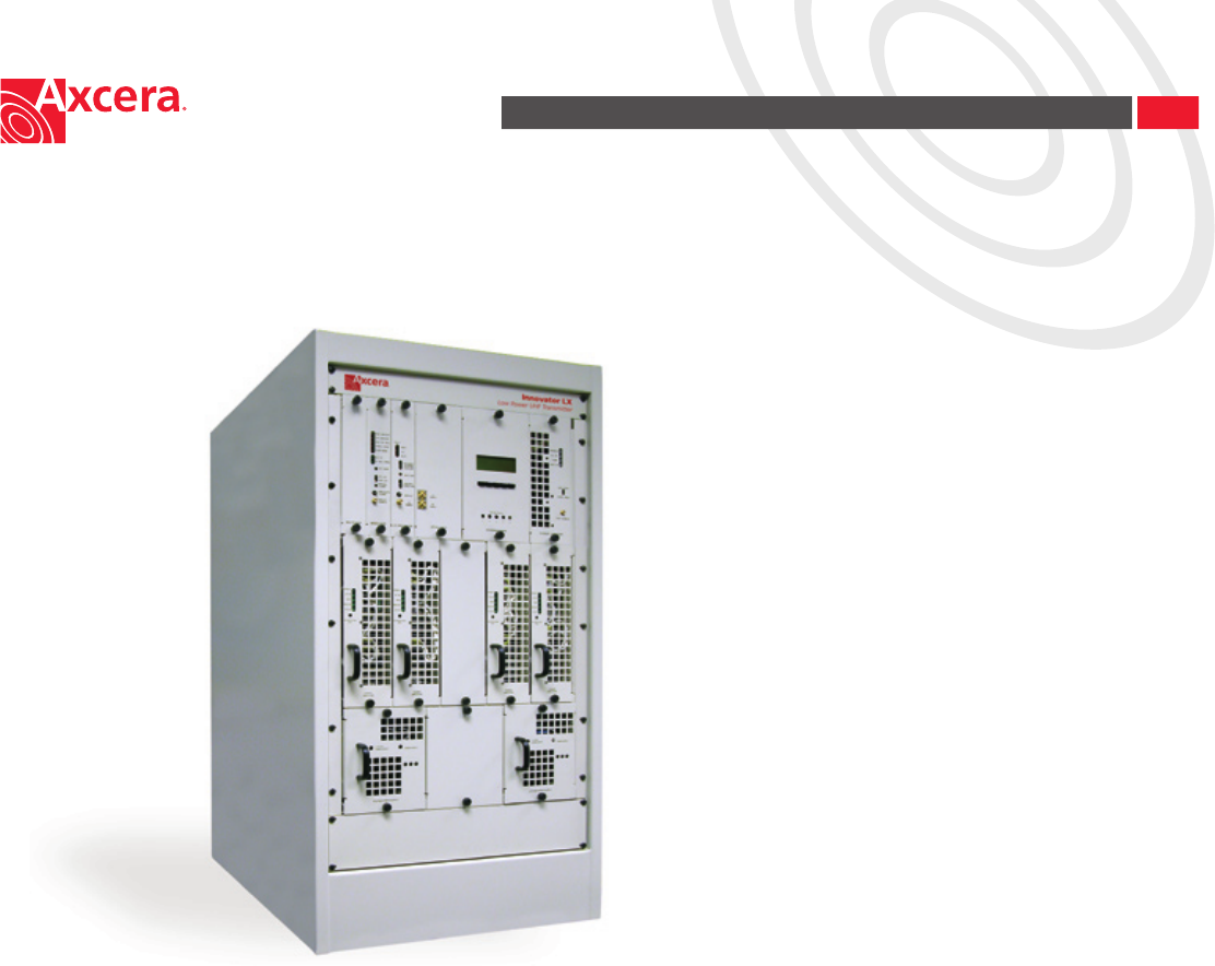
Innovator LX (Preliminary)
Low Power Transmitter 10W-6kW
Designed to provide broadcasters with a product that will meet their needs like
no other solution on the market, this new low to medium power transmitter
line uses the latest LDMOS devices for broadband operation across the entire
UHF band. This allows users to minimize spare parts stock, which is especially
important to group owners and networks, and also enables simple and
inexpensive channel changes.
The very compact and completely modular design uses a chassis/backplane
conguration with parallel amplier and power supply modules that can be
removed and replaced while the transmitter is on the air. Additionally, the
Innovator LX series was designed to be eld upgradable to digital operation.
Congurations are available in power levels from 10 watts to 6 kilowatts
analog and up to 3 kilowatts DTV, and all are manufactured in the USA by
Axcera - The RF Experts.

Speci cations published here are current as of the date of publication of this document. Because we are continuously improving our products, Axcera reserves the right to
change speci cations without prior notice. At any time, you may verify product speci cations by contacting our of ce. Axcera views it’s patent portfolio as an important
corporate asset and vigorously enforces its patents. Products or features contained herein may be covered by one or more U.S. or foreign patents.
0311R3 © 2003 AXCERA All Rights Reserved An Equal Opportunity Employer A Platinum Equity Company
Visual Performance
Frequency Range 470 to 806 MHz
Carrier Stability (Transmitters)
Standard ±1 kHz
Optional ±350 Hz
w/PFC ±1Hz
Frequency Translation Stability (Translators)
Standard ±1 kHz
Optional ±350 Hz
w/PFC ±1Hz
Regulation of RF Output Power 3%
Output Variation (Over 1 Frame) 2%
Sideband Response
-1.25 MHz and below -20 dB
-0.75 to -0.5 MHz +0.5 db, -2 dB
-0.5 to +3.58 MHz ±0.5 dB
+3.58 MHz to +4.18 MHz +0.5, -1.0 dB
Freq Response vs. Brightness ±0.5 dB
Visual Modulation Capability 1%
Differential Gain 5%
Incidental Phase Modulation ±3°
Linearity (Low Frequency) 5%
Aural Performance
Frequency Deviation Capability ±75 kHz
(Transmitters)
Distortion 0.5%
FM Noise -60 dB
AM Noise -55 dB
Aural to Visual Separation 4.5 MHz
± 100Hz
Composite Audio Input (Multi-channel sound)
(Transmitters)
Input Level 1V peak,
nominal
Input Impedance 75 ohms,
unbalanced
Frequency Range
±0.1 dB response 50 Hz to 50 kHz
±0.5 dB response 30 Hz to 120 kHz
Monaural Audio Input (Transmitters)
Input Level 0 to +10 dBm
Input 600 ohms,
balanced
Freq Range (±0.5 dB resp.) 30 Hz to 15 kHz
Pre-emphasis 75µs
Subcarrier Input (Transmitters)
Input Level 1V peak,
nominal
Input Impedance 75 ohms,
unbalanced
Freq Range (±0.5 dB resp.) 20 kHz to
120 kHz
Innovator LX (Preliminary)
Low Power Transmitter 10W - 6kW
Visual Performance (continued)
Differential Phase ±3°
Signal-to-Noise Ratio 55 dB
2t K-Factor 2%
Noise Factor (Translators) 5 dB (Max)
w/Input Preamp 3 dB (Max)
Input Dynamic Range (Translators) -60 dB to
-15 dBm
w/Input Preamp -75 dBm
to -30 dBm
Env. Delay (Transmitters) Per FCC Standard
Video Input (Transmitters) 75 ohms
(Loop through)
Harmonics -60 dB or better
Intermodulation Products -52 dB or better
Spurious (›3 MHz from channel edge)
100W and lower -50dB or better
Greater than 100W -60dB or better
General
Model Number* LU10Ax LU100Ax LU250Ax LU500Ax LU1000Ax LU2000Ax LU3000Ax LU4000Ax LU5000Ax LU6000Ax
Power Output (Watts)
Visual (Peak) 10 100 250 500 1000 2000 3000 4000 5000 6000
Aural (Avg.) 1 10 25 50 100 200 300 400 500 600
Output Connector N N 7/8” EIA 7/8” EIA 7/8” EIA 7/8” EIA 31/8” EIA 31/8” EIA 31/8” EIA 31/8” EIA
Power Consumption (Watts) 250 675 1100 1900 3500 6700 10,250 13,500 16,700 19,900
Input Power
Line Voltage (Volts) 117/230 ±10% 230 ± 10%
Power Requirements Single Phase, 50 or 60 Hz
Size (H x W x D) 8.75”x19”x23” 55”x22”x34” 76”x22”x34” 76”x44”x34”
(Chassis Only)
Weight (lbs.) 45 45 340 360 400 550 700 1030 1180 1330
Operational Temperature Range 0 to +50°, derate 2°C/1000 ft.
Maximum Altitude3 8500 feet (2600m) AMSL
Operational Humidity Range 0% to 95% non-condensing
RF Load Impedance 50 Ω
* For transmitters use “T” suf x, translators use “L” suf x (ex. LU100AT - 100W Transmitter)
APPENDIX B
DRAWINGS AND PARTS LISTS

LX Series Analog Power Amplifier Assembly Appendix B, Drawings and Parts Lists
LX Series, Rev. 1 B-1
LX Series High Power System
LX Series Transmitter Block Diagrams……………………………………………. (6 kW) 1304561
LX Series System Typical Racking Plan Drawings………………………….. (6 kW) 1304310
Chassis Assembly, Power Amplifier, LX Series
250W LX Series Power Amplifier Chassis Assembly Block Diagram.............1305195
500W/1 kW LX Series AC Harness Chassis/Airbox I/C.............................1303960
500W/1 kW LX Series DC Harness Chassis/Airbox I/C.............................1303961
500W/1 kW LX Series Coax Assembly Chassis/Airbox Interconnect...........1303480
Chassis Assembly, Power Amplifier, LX Series - continued
2 Way Splitter/Phase Shifter Assembly (Used with multiple Power Amplifier Assemblies)
2 Way Splitter/Phase Shifter Schematic .............................................1303569
4 Way Splitter Module Assembly (Used with multiple Power Amplifier Assemblies)
Contains a 4 Way Splitter Board (1303234).
4 Way Splitter Board
Schematic ....................................................................................1303237
4 Way Combiner Module Assembly (Used with four Power Amplifier Assemblies)
(This combiner or the 1303545 combiner will be used)
4 Way Combiner Board Schematic .....................................................1303655
External Amplifier Signal Board, LX Series
Schematic ....................................................................................1303346
Visual/Aural Metering Board
Schematic .................................................................................1265-3309
Power Amplifier Assembly, 250 Watt, LX Series
(Each Amplifier Assembly supplies 250 Watts)
Block Diagram................................................................................1303585
Interconnect.................................................................................1303510
RF Module Pallet w/o Transistors
Made into a RF Module Pallet, w/ Philips Transistors (1300116).
Schematic ..................................................................51-5379-309-00 WSP
RF Module Pallet, Philips
Made from a RF Module Pallet w/o Transistors (1152336).
Amplifier Control Board
Schematic ....................................................................................1303683
150-Watt UHF Driver Pallet Assembly
Schematic ....................................................................................1303171
2-Way Combiner Board Assembly
Schematic ....................................................................................1303211
UHF Phase/Gain Board
Schematic ....................................................................................1303216

LX Series Analog Power Amplifier Assembly Appendix B, Drawings and Parts Lists
LX Series, Rev. 1 B-2
Power Supply Assembly, 1 kW, LX Series
(One Power Supply Assembly Supplies Power to Two Amplifier Assemblies)
Block Diagram................................................................................1303886
Interconnect.................................................................................1303479
APPENDIX C
TRANSMITTER LOG SHEET

UHF LX Series Transmitter/Translator Appendix C, Log Sheet
- Page 1 of 1 -
DESCRIPTION OF
PARAMETER TRANSMITTER READING FROM LCD DISPLAY
DATE READINGS TAKEN
Model Number
Code Version
Firmware Number
OUTPUT MEASUREMENTS
% VISUAL POWER
% AURAL POWER
RECEIVER DETAILS NOT USED WITH TRANSMITTER
AFC 1 LEVEL
PLL 1 CIRCUIT
ALC INPUT
FAULT AT
MODULATOR DETAILS MAY NOT BE USED WITH TRANSLATOR
PLL CIRCUIT
OUTPUT LEVEL
AURAL DEVIATION
CW INPUT
CALL SIGN
IF PROCESSOR DETAILS
INPUT SIGNAL STATE
MODULATION
INPUT IF
DLC CONTROL LOCK
ALC LEVEL
ALC MODE
UPCONVERTER DETAILS
AFC 1 LEVEL
AFC 2 LEVEL
CODE VERSION
PLL 1 CIRCUIT
PLL 2 CIRCUIT
AGC 1 LEVEL
AGC 2 LEVEL
INT. 10 MHz
SYSTEM CONTROL DETAILS
Power Supply Enable For

UHF LX Series Transmitter/Translator Appendix C, Log Sheet
- Page 2 of 2 -
DESCRIPTION OF
PARAMETER TRANSMITTER READING FROM LCD DISPLAY
DRIVER AND PA DETAILS
POWER SUPPLY STATE, 32V
FORWARD POWER
REFLECTED POWER
AMP 1 CURRENT
AMP 2 CURRENT
TEMPERATURE
CODE VERSION
PA HAS OPERATED FOR
EXT. PA AMPLIFIER MODULES ONLY IN HIGH POWER SYSTEMS
AMP SET 1 MODULE 1 Will indicate Amp Set and Module within the
Set. Will step through each Set and Module.
POWER SUPPLY VOLTAGE, 32V
32V SUPPLY
FORWARD POWER
REFLECTED POWER
AMP CURRENT 1
AMP CURRENT 2
AMP CURRENT 3
AMP TEMPERATURE
CODE VERSION
PA HAS OPERATED FOR
AMP SET 1 MODULE 2
POWER SUPPLY VOLTAGE, 32V
32V SUPPLY
FORWARD POWER
REFLECTED POWER
AMP CURRENT 1
AMP CURRENT 2
AMP CURRENT 3
AMP TEMPERATURE
CODE VERSION
PA HAS OPERATED FOR
AMP SET 1 MODULE 3
POWER SUPPLY VOLTAGE, 32V
32V SUPPLY
FORWARD POWER
REFLECTED POWER
AMP CURRENT 1
AMP CURRENT 2
AMP CURRENT 3
AMP TEMPERATURE
CODE VERSION
PA HAS OPERATED FOR

UHF LX Series Transmitter/Translator Appendix C, Log Sheet
- Page 3 of 3 -
DESCRIPTION OF
PARAMETER TRANSMITTER READING FROM LCD DISPLAY
AMP SET 1 MODULE 4
POWER SUPPLY VOLTAGE, 32V
32V SUPPLY
FORWARD POWER
REFLECTED POWER
AMP CURRENT 1
AMP CURRENT 2
AMP CURRENT 3
AMP TEMPERATURE
CODE VERSION
PA HAS OPERATED FOR
AMP SET 2 MODULE 1
POWER SUPPLY VOLTAGE, 32V
32V SUPPLY
FORWARD POWER
REFLECTED POWER
AMP CURRENT 1
AMP CURRENT 2
AMP CURRENT 3
AMP TEMPERATURE
CODE VERSION
PA HAS OPERATED FOR
AMP SET 2 MODULE 2
POWER SUPPLY VOLTAGE, 32V
32V SUPPLY
FORWARD POWER
REFLECTED POWER
AMP CURRENT 1
AMP CURRENT 2
AMP CURRENT 3
AMP TEMPERATURE
CODE VERSION
PA HAS OPERATED FOR
AMP SET 2 MODULE 3
POWER SUPPLY VOLTAGE, 32V
32V SUPPLY
FORWARD POWER
REFLECTED POWER
AMP CURRENT 1
AMP CURRENT 2
AMP CURRENT 3
AMP TEMPERATURE
CODE VERSION
PA HAS OPERATED FOR

UHF LX Series Transmitter/Translator Appendix C, Log Sheet
- Page 4 of 4 -
DESCRIPTION OF
PARAMETER TRANSMITTER READING FROM LCD DISPLAY
AMP SET 2 MODULE 4
POWER SUPPLY VOLTAGE, 32V
32V SUPPLY
FORWARD POWER
REFLECTED POWER
AMP CURRENT 1
AMP CURRENT 2
AMP CURRENT 3
AMP TEMPERATURE
CODE VERSION
PA HAS OPERATED FOR
AMP SET 3 MODULE 1
POWER SUPPLY VOLTAGE, 32V
32V SUPPLY
FORWARD POWER
REFLECTED POWER
AMP CURRENT 1
AMP CURRENT 2
AMP CURRENT 3
AMP TEMPERATURE
CODE VERSION
PA HAS OPERATED FOR
AMP SET 3 MODULE 2
POWER SUPPLY VOLTAGE, 32V
32V SUPPLY
FORWARD POWER
REFLECTED POWER
AMP CURRENT 1
AMP CURRENT 2
AMP CURRENT 3
AMP TEMPERATURE
CODE VERSION
PA HAS OPERATED FOR
AMP SET 3 MODULE 3
POWER SUPPLY VOLTAGE, 32V
32V SUPPLY
FORWARD POWER
REFLECTED POWER
AMP CURRENT 1
AMP CURRENT 2
AMP CURRENT 3
AMP TEMPERATURE
CODE VERSION
PA HAS OPERATED FOR

UHF LX Series Transmitter/Translator Appendix C, Log Sheet
- Page 5 of 5 -
DESCRIPTION OF
PARAMETER TRANSMITTER READING FROM LCD DISPLAY
AMP SET 3 MODULE 4
POWER SUPPLY VOLTAGE, 32V
32V SUPPLY
FORWARD POWER
REFLECTED POWER
AMP CURRENT 1
AMP CURRENT 2
AMP CURRENT 3
AMP TEMPERATURE
CODE VERSION
PA HAS OPERATED FOR
AMP SET 4 MODULE 1
POWER SUPPLY VOLTAGE, 32V
32V SUPPLY
FORWARD POWER
REFLECTED POWER
AMP CURRENT 1
AMP CURRENT 2
AMP CURRENT 3
AMP TEMPERATURE
CODE VERSION
PA HAS OPERATED FOR
AMP SET 4 MODULE 2
POWER SUPPLY VOLTAGE, 32V
32V SUPPLY
FORWARD POWER
REFLECTED POWER
AMP CURRENT 1
AMP CURRENT 2
AMP CURRENT 3
AMP TEMPERATURE
CODE VERSION
PA HAS OPERATED FOR
AMP SET 4 MODULE 3
POWER SUPPLY VOLTAGE, 32V
32V SUPPLY
FORWARD POWER
REFLECTED POWER
AMP CURRENT 1
AMP CURRENT 2
AMP CURRENT 3
AMP TEMPERATURE
CODE VERSION
PA HAS OPERATED FOR

UHF LX Series Transmitter/Translator Appendix C, Log Sheet
- Page 6 of 6 -
DESCRIPTION OF
PARAMETER TRANSMITTER READING FROM LCD DISPLAY
AMP SET 4 MODULE 4
POWER SUPPLY VOLTAGE, 32V
32V SUPPLY
FORWARD POWER
REFLECTED POWER
AMP CURRENT 1
AMP CURRENT 2
AMP CURRENT 3
AMP TEMPERATURE
CODE VERSION
PA HAS OPERATED FOR
AMP SET 5 MODULE 1
POWER SUPPLY VOLTAGE, 32V
32V SUPPLY
FORWARD POWER
REFLECTED POWER
AMP CURRENT 1
AMP CURRENT 2
AMP CURRENT 3
AMP TEMPERATURE
CODE VERSION
PA HAS OPERATED FOR
AMP SET 5 MODULE 2
POWER SUPPLY VOLTAGE, 32V
32V SUPPLY
FORWARD POWER
REFLECTED POWER
AMP CURRENT 1
AMP CURRENT 2
AMP CURRENT 3
AMP TEMPERATURE
CODE VERSION
PA HAS OPERATED FOR
AMP SET 5 MODULE 3
POWER SUPPLY VOLTAGE, 32V
32V SUPPLY
FORWARD POWER
REFLECTED POWER
AMP CURRENT 1
AMP CURRENT 2
AMP CURRENT 3
AMP TEMPERATURE
CODE VERSION
PA HAS OPERATED FOR

UHF LX Series Transmitter/Translator Appendix C, Log Sheet
- Page 7 of 7 -
DESCRIPTION OF
PARAMETER TRANSMITTER READING FROM LCD DISPLAY
AMP SET 5 MODULE 4
POWER SUPPLY VOLTAGE, 32V
32V SUPPLY
FORWARD POWER
REFLECTED POWER
AMP CURRENT 1
AMP CURRENT 2
AMP CURRENT 3
AMP TEMPERATURE
CODE VERSION
PA HAS OPERATED FOR
AMP SET 6 MODULE 1
POWER SUPPLY VOLTAGE, 32V
32V SUPPLY
FORWARD POWER
REFLECTED POWER
AMP CURRENT 1
AMP CURRENT 2
AMP CURRENT 3
AMP TEMPERATURE
CODE VERSION
PA HAS OPERATED FOR
AMP SET 6 MODULE 2
POWER SUPPLY VOLTAGE, 32V
32V SUPPLY
FORWARD POWER
REFLECTED POWER
AMP CURRENT 1
AMP CURRENT 2
AMP CURRENT 3
AMP TEMPERATURE
CODE VERSION
PA HAS OPERATED FOR
AMP SET 6 MODULE 3
POWER SUPPLY VOLTAGE, 32V
32V SUPPLY
FORWARD POWER
REFLECTED POWER
AMP CURRENT 1
AMP CURRENT 2
AMP CURRENT 3
AMP TEMPERATURE
CODE VERSION
PA HAS OPERATED FOR

UHF LX Series Transmitter/Translator Appendix C, Log Sheet
- Page 8 of 8 -
DESCRIPTION OF
PARAMETER TRANSMITTER READING FROM LCD DISPLAY
AMP SET 6 MODULE 4
POWER SUPPLY VOLTAGE, 32V
32V SUPPLY
FORWARD POWER
REFLECTED POWER
AMP CURRENT 1
AMP CURRENT 2
AMP CURRENT 3
AMP TEMPERATURE
CODE VERSION
PA HAS OPERATED FOR
NOTE: The previous Log Sheet readings can be taken from the System Details
Screen, Menu 30-1, on the 4 x 20 Display located on the front of the Control &
Monitoring/Power Supply Module.