UDP Technology IPN100HD IP NETWORK CAMERA User Manual IPX IPN Series
UDP Technology, Ltd. IP NETWORK CAMERA IPX IPN Series
User Manual
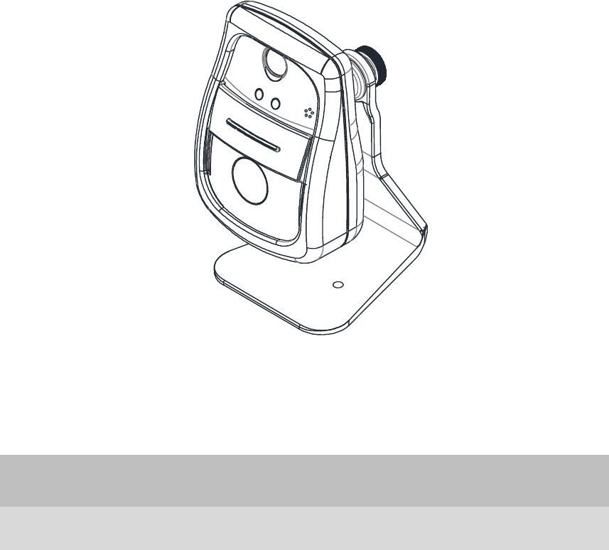
IPN100HD
Installation Guide
ETHERNET
DO DI
Out In
Com
DC12V
Com
INFORMATION TO USER
CAUTION
RISK OF ELECTRIC SHOCK,
DO NOT OPEN
!
CAUTION: TO REDUCE THE RISK OF ELECTRIC SHOCK,
DO NOT REMOVE COVER (OR BACK).
NO USER SERVICEABLE PARTS INSIDE.
REFER SERVICING TO QUALIFIED SEERIVCE PERSONEL.
This symbol is intended to alert the user to the presence of un-insulated
“dangerous voltage” within the product’s enclosure that may be of sufficient
magnitude to constitute a risk of electric shock to persons.
!
This symbol is intended to alert the user to the presence of important
operating and maintenance (servicing) instructions in the literature
accompanying the appliance.

IPX/IPN Series IPN100HD Installation Guide
01A.00 UDP Technology Ltd. 3
Table of Contents
1. FEATURES ............................................................................................................. 4
2. PACKAGE CONTENTS............................................................................................. 5
3. PART NAMES ........................................................................................................ 6
4. INSTALLATION ...................................................................................................... 8
4.1. Lens Position ...................................................................................................................... 9
4.2. Setting the Image Attribute ............................................................................................... 9
5. CONNECTIONS .................................................................................................... 10
5.1. Connectors ....................................................................................................................... 10
6. CONFIGURATION ................................................................................................ 12
6.1. Set up network environment ........................................................................................... 12
6.1.1. Generic IP Environment ............................................................................................ 12
6.1.2. Custom IP Environment............................................................................................. 13
6.2. View video on web page .................................................................................................. 14
6.3. Reset ................................................................................................................................. 15
6.4. Factory Default ................................................................................................................. 15
APPENDIX (A): SPECIFICATIONS .............................................................................. 16
Summary ................................................................................................................................. 16
Functional Features ................................................................................................................. 17
Environment Characteristics ................................................................................................... 17
Environment Characteristics ................................................................................................... 17
Mechanical Characteristics ..................................................................................................... 17
APPENDIX (B): DIMENSIONS ................................................................................... 18
APPENDIX (C): HEXADECIMAL-DECIMAL CONVERSION TABLE .................................. 19
REVISION HISTORY ................................................................................................. 20

IPX/IPN Series IPN100HD Installation Guide
01A.00 UDP Technology Ltd. 4
1. FEATURES
Camera
Indoor Cube IP Camera
HD720 (1280 x 720) streaming
1/4” 720p CMOS
Improvement of color rolling suppression
Streaming
Dual streaming mode
Burnt-in text supported
Unicast supported
Video/Audio
Video compression: H.264/ MJPEG, 30FPS@720p
Audio compression: G.711(µLaw, aLaw)
Built-in video motion detection
Two-way mono audio supported
Network
RTSP/ HTTP protocol supported
10/100 Base-T Ethernet
Additional Features
Micro SD card supported
(Indoor model built-in, Outdoor model available with factory order only)Built-in Video
Content Analysis
SDK (Software Development Kit) provided
VCA (Video Content Analysis)
VCA Presence (Standard)
VCA Surveillance (Optional)
IPX/IPN Series IPN100HD Installation Guide
01A.00 UDP Technology Ltd. 5
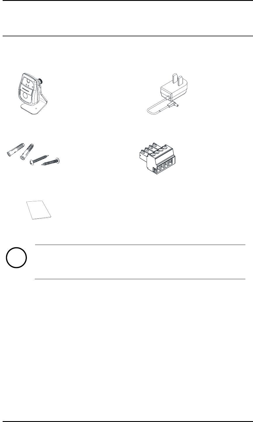
2. PACKAGE CONTENTS
Unpack carefully and handle the equipment with care. The packaging contains:
Camera
DC power adaptor
Screws and Anchor blocks
4 Pin terminal block
Quick Installation Guide
Note
i
Package contents are subject to change without prior notice.
ETHERNET
DO DI
Out In
Com
DC12V
Com
IPX/IPN Series IPN100HD Installation Guide
01A.00 UDP Technology Ltd. 6
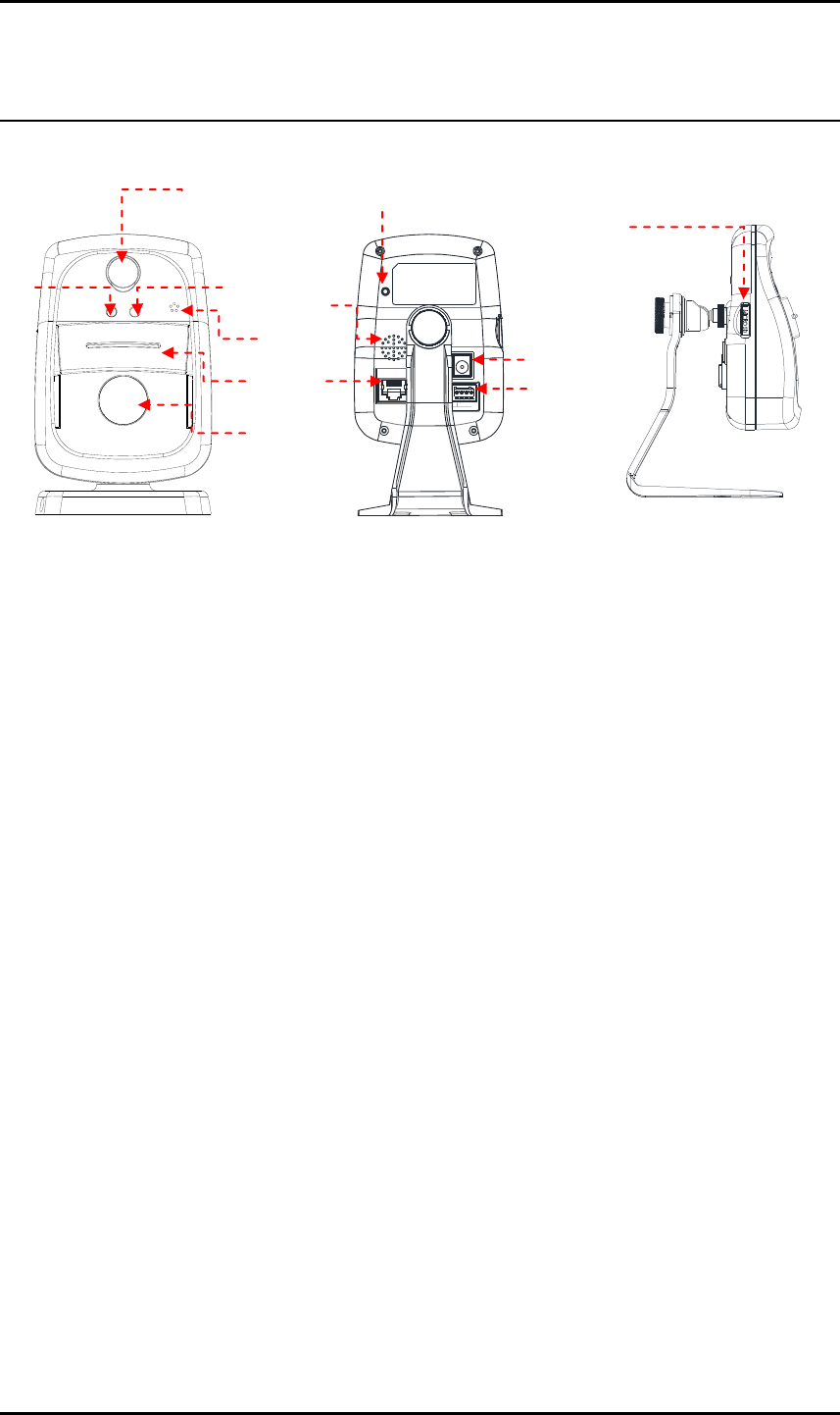
3. PART NAMES
① PIR sensor
Detects movement of objects
② Sensor indicator LED
When PIR sensor detects, the indicator glows in red
③ Status LED
LED glows in green when the device is connected
④ Microphone
Built-in microphone
⑤ Privacy Shutter
Manual shutter to close the lens
⑥ Camera lens
Prepositioned 1/4” 720p CMOS sensor
⑦ Reset button
The reset button can be used for restarting the device or resetting it to Factory Default. Refer to 6.3. Re
set and 6.4. Factory Default for more details.
⑧ Speaker
Built-in speaker
⑨ LAN Connector (Ethernet)
This is a RJ45 LAN connector for 10/100 Base-T Ethernet.
⑩ Power Adaptor Connector (DC 12V)
The camera needs a DC 12V adapter for power supply.
②
* Models herein and their appearance are subject to change without any prior notice.
⑥
①
③
④
⑤
⑪
ETHERNET
DO DI
Out In
Com
DC12V
Com
⑦
⑧
⑨
⑩
○
12

IPX/IPN Series IPN100HD Installation Guide
01A.00 UDP Technology Ltd. 7
⑪ 4 pin terminal block for D/I, D/O
4 pin terminal block for D/I and D/O
⑫ Micro SD Card Socket
Memory card slot for external storage. Supports up to 32GB.
IPX/IPN Series IPN100HD Installation Guide
01A.00 UDP Technology Ltd. 8
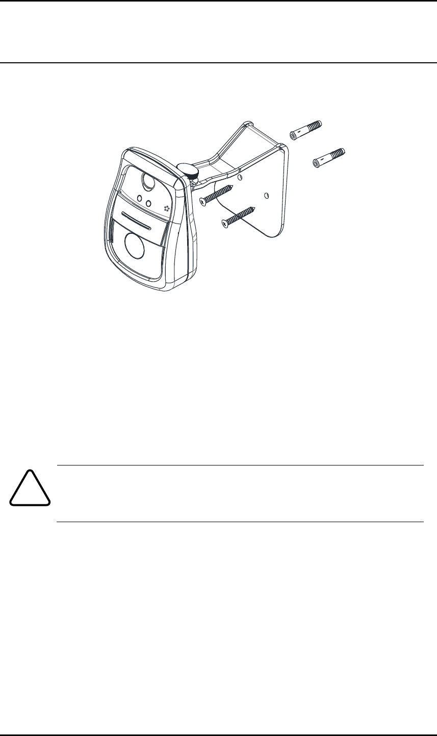
4. INSTALLATION
1) Drill two holes on the desired position of installation and insert anchor blocks into
the holes.
2) Position the mount bracket to anchor blocks.
3) Fasten the mount bracket with screws.
4) Manually position the camera to area where it will be monitored.
To prevent camera falling off from the mounted area, make sure the mounted
surface firm and stable enough to support the camera. If any reinforcement is
needed, consult with your safety personnel and proceed with the installation.
Caution
!
IPX/IPN Series IPN100HD Installation Guide
01A.00 UDP Technology Ltd. 9
4.1. Lens Position
IPN100HD’s lens is prepositioned. While installing with wall-mount bracket, position the
camera body where images will be captured.
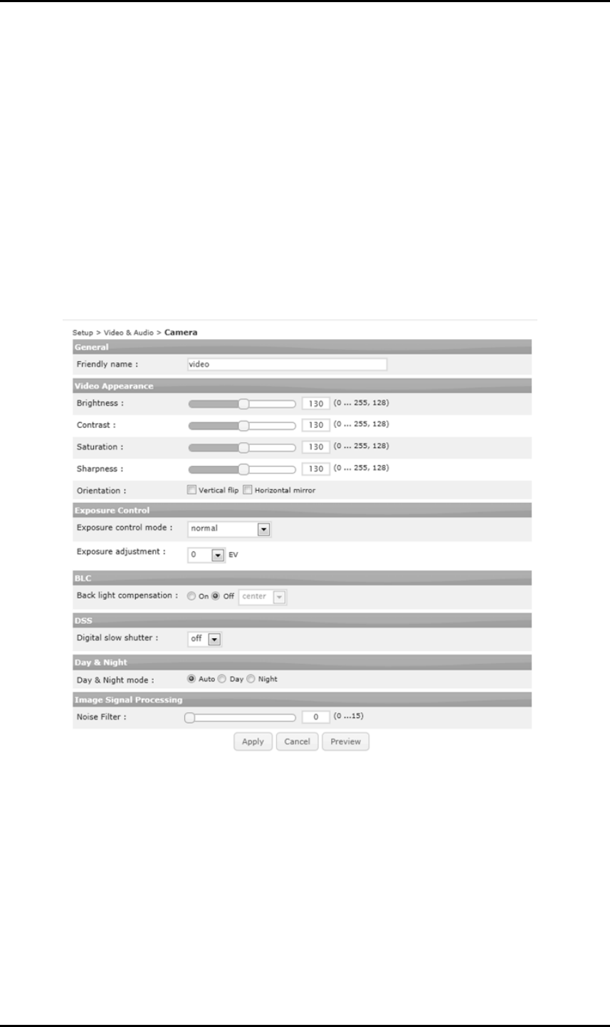
4.2. Setting the Image Attribute
Image attributes can be configured through the web interface. (Microsoft® Internet Explorer
recommended) The menu of image attribute can be found under Setup > Video & Audio >
Camera. Through setting menu, brightness, contrast, saturation and sharpness, orientation,
exposure control, backlight compensation, digital slow shutter (DSS), day and night mode, and
image noise filter can be adjusted.
IPX/IPN Series IPN100HD Installation Guide
01A.00 UDP Technology Ltd. 10
5. CONNECTIONS
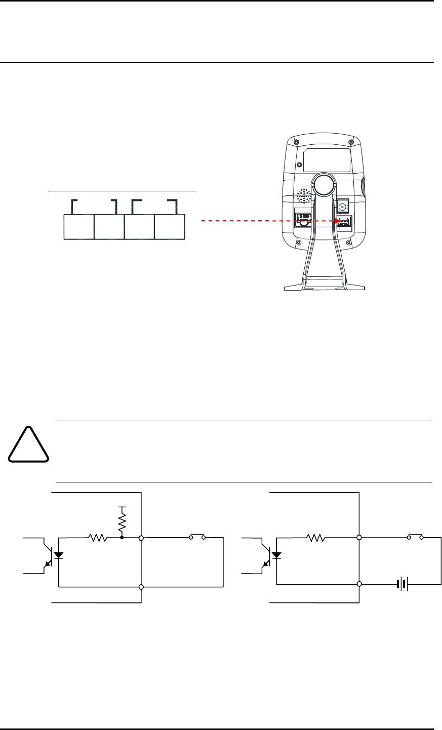
5.1. Connectors
① Sensor (DI) connection
The camera provides 1 channel D/I. It can be connected to either a voltage type sensor or a
relay type sensor as the following figures. It can be selected by software.
Input voltage range: 0VDC minimum to 5VDC maximum, Max 50mA
Input voltage threshold: 4.5V
Caution
!
Do not exceed the maximum input voltage or relay rate.
② Alarm (DO) connection
Only the relay type is supported.
Relay Rating: Max 24VAC 500mA or 12VDC 1A
+5V
DI
COM
DI
COM
+
-
Relay Type
Voltage Type
+
-
Output of
Sensor
Output of
Sensor
Internal
Internal
+
-
ETHERNET
DO DI
Out In
Com
DC12V
Com
ETHERNET
DO DI
Out In
Com
DC12V
Com
①
②
IPX/IPN Series IPN100HD Installation Guide
01A.00 UDP Technology Ltd. 11
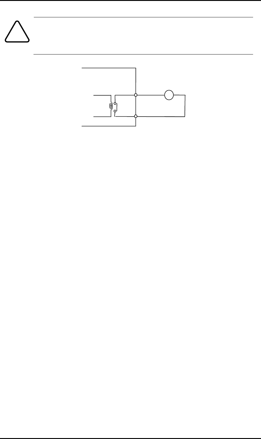
Caution
!
Do not exceed the maximum relay rating.
DO
COM
Relay Type
Device
Internal
IPX/IPN Series IPN100HD Installation Guide
01A.00 UDP Technology Ltd. 12
6. CONFIGURATION
6.1. Set up network environment
The default IP address of the device is 192.168.XXX.XXX. Users can identify the IP address of the
device from converting the MAC address’s hexadecimal numbers, which is attached to the
device. Be sure that the device and PC are on a same area network before running the
installation.
IP address : 192.168.xxx.xxx
Subnet mask: 255.255.0.0
6.1.1. Generic IP Environment
In case of generic private network environment where IP address 192.168.XXX.XXX are used,
users may view the live streaming images on a web page using the device’s default IP address:
1. Convert the device’s MAC address to the IP address. Refer to the Hexadecimal-Decimal
Conversion Chart at the end of the manual.
(The MAC address of the device is attached on the side or bottom of the device.)
2. Start the Microsoft® Internet Explorer web browser and enter the address of the device.
3. Web streaming and device configurations are supported through ActiveX program. When the
ActiveX installation window appears, authorize and install the ActiveX.
MAC address = 00-13-23-01-14-B1 → IP address = 192.168.20.177
Convert the last two set of hexadecimal numbers to decimal numbers.
IPX/IPN Series IPN100HD Installation Guide
01A.00 UDP Technology Ltd. 13
6.1.2. Custom IP Environment
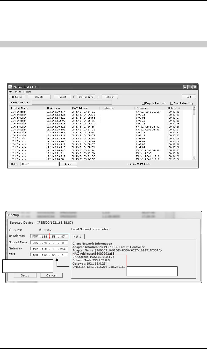
IPAdminTool is provided with SDK at the following SDK path.
{SDK root}\BIN\TOOLS\AdminTool\
IPAdminTool is a management tool, which automatically scans all of the network products for
users to perform administrative tasks, which includes network configurations, firmware update,
device reboot, and device organizations.
To modify the device’s default IP address for customized network area;
1. Find the device from the IPAdminTool’s list and highlight the device’s name.
2. Right-click the mouse and select “IP Address”; IP Setup window appears.
3. In the IP Setup’s window, information under ‘Local Network information’ displays the
user/PC’s network area information. Those information need to be incorporated to the IP
Address, Subnet Mask, Gateway, and DNS boxes, except the last 2 sets of IP Address, which
are to be the unique numbers for the device. Refer to the image above for the setting
4. Click ‘Setup’ to complete the modification.
PC environment Info
Give new unique IP
address in last two sets
IPX/IPN Series IPN100HD Installation Guide
01A.00 UDP Technology Ltd. 14
6.2. View video on web page
Type the proper IP address to view the live streaming images through a web browser.
The default username and password is root / pass.
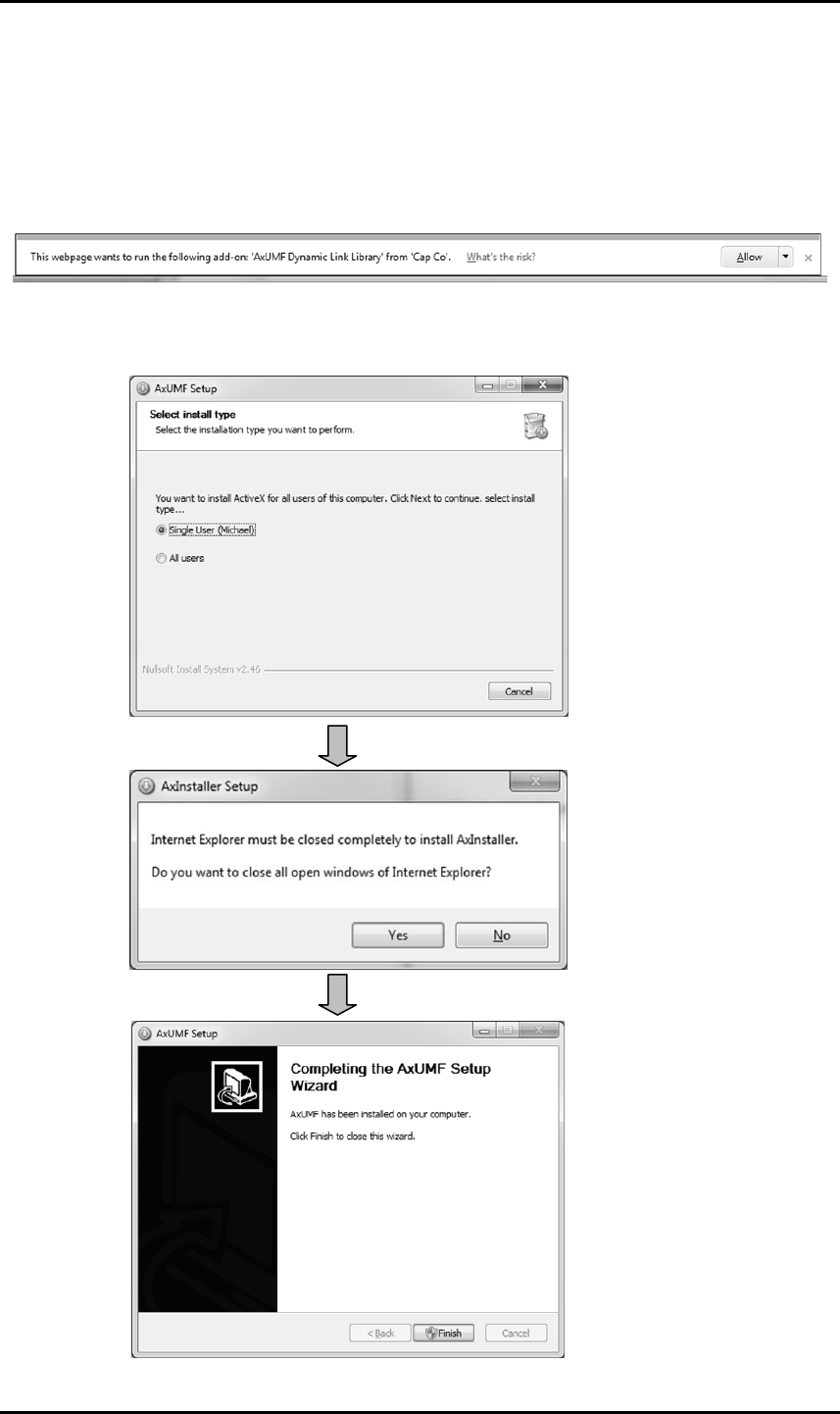
1. The browser asks to install the ActiveX. Click Allow.
2. Setup.exe installation link or pop-up window appears, depends on Microsoft® Internet
Explorer version. Proceed with rest of setup installation.

IPX/IPN Series IPN100HD Installation Guide
01A.00 UDP Technology Ltd. 15
3. Follow the instructions of the dialog boxes and complete the installation. Once the
installation is complete, start the web browser again and check if video stream is
displayed in the main view frame.
4. Depends on Microsoft® Internet Explorer version, the web browser might need to be
refreshed or restart. Accesses the web address after all ActiveX are installed.
6.3. Reset
1. While the device is on, press the reset button for 1~2 seconds.
2. Wait for the system to reboot.
6.4. Factory Default
1. While the device is on, press reset button and hold.
2. Release the Reset button after about 5 seconds when green LED blinks, which is located in
the front panel, at rate of 200ms.
3. Wait for the system to reboot.
The factory default settings can be inferred as follows:
IP address: 192.168.xx.yy
Network mask: 255.255.0.0
Gateway: 192.168.0.1
User ID: root
Password: pass

IPX/IPN Series IPN100HD Installation Guide
01A.00 UDP Technology Ltd. 16
APPENDIX (A): SPECIFICATIONS
Summary
Camera Module
Image Sensor
1/4” 720p CMOS
Effective Pixels
1280 x 720
Scanning System
Progressive scanning
AGC Control
Auto
Minimum Illumination
Color : 1.0 lux, BW : 0.001 lux(Sens-up 32X)
Lens
2.7mm F2.0 Megapixel
Field of View
91° (Horizontal)
Day & Night
Software
Smart Edge Enhance
Supported (Auto adjust the sharpness by Lux)
2D-DNR
Supported (1 ~ 16)
DSS (Sens-up)
2X ~ 32X
White Balance
ATW / Manual / Push
BLC
On(possible to designate zone) / Off
Video
Compression Format
H.264, MJPEG
Number of Streams
Dual Stream, Configurable
Resolution
1280 x 720, 800 x 450, 480 x 270, 320 x 180
Compression FPS
30fps@720p
Motion Detection
Built-in
Burnt-in Text
Video stream overlay text
Audio
Input
1 Built-in Mic.
Output
1 Built-in Speaker
Compression Format
G.711

IPX/IPN Series IPN100HD Installation Guide
01A.00 UDP Technology Ltd. 17
Functional Features
Digital Input and Output
1 / 1
PIR Sensor
Supported
Network
10 / 100 Base-T
Wi-Fi
Supported (11b/g/n)
Protocol
TCP/IP, UDP/IP, HTTP, RTSP, RTCP, RTP/UDP, RTP/TCP, SNTP,
mDNS, UPnP, SMTP, IGMP, DHCP, DDNS, SSL v2/v3, IEEE
802.1X, SNMP v2/v3
SD Memory (microSD)
Built-in with slot
Privacy Shutter
Detecting Position of Shutter On/Off
Environment Characteristics
Power Source
DC 12V
Power over Ethernet
None
Power Consumption
(Approx)
400mA @ DC 12V
Environment Characteristics
Fan / Heater
None
Operating Temperature
DC12V : 0˚C ~ 50˚C (32˚F ~ 122˚F)
Operating Humidity
Up to 85% RH, Non-condensing
Certification
FCC Class B, CE, KC, RoHS
IP Protection Ration
No
Mechanical Characteristics
Material
Plastic (PC + ABS)
Color
Ivory
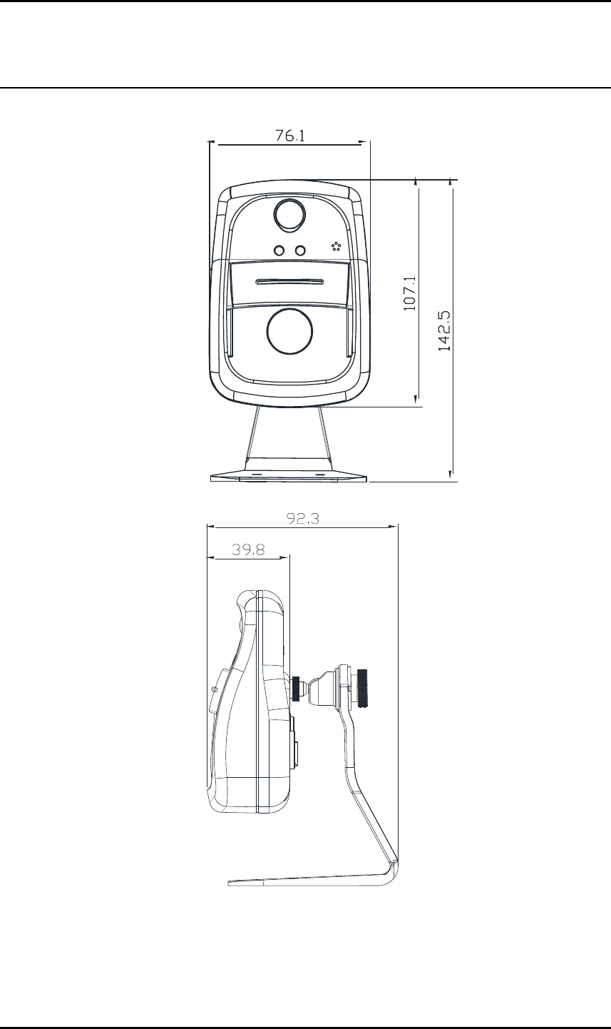
Dimension
76(W) x 107(H) x 40(D)mm
Weight (Approx)
1,170g
IPX/IPN Series IPN100HD Installation Guide
01A.00 UDP Technology Ltd. 18
APPENDIX (B): DIMENSIONS
(Unit: mm)
ETHERNET
DO DI
Out In
Com
DC12V
Com
ETHERNET
DO DI
Out In
Com
DC12V
Com

IPX/IPN Series IPN100HD Installation Guide
01A.00 UDP Technology Ltd. 19
APPENDIX (C): HEXADECIMAL-DECIMAL
CONVERSION TABLE
Refer to the following table when you convert the MAC address of your device to IP address.
Hex
Dec
Hex
Dec
Hex
Dec
Hex
Dec
Hex
Dec
Hex
Dec
Hex
Dec
0
0
25
37
4A
74
6F
111
94
148
B9
185
DE
222
1
1
26
38
4B
75
70
112
95
149
BA
186
DF
223
2
2
27
39
4C
76
71
113
96
150
BB
187
E0
224
3
3
28
40
4D
77
72
114
97
151
BC
188
E1
225
4
4
29
41
4E
78
73
115
98
152
BD
189
E2
226
5
5
2A
42
4F
79
74
116
99
153
BE
190
E3
227
6
6
2B
43
50
80
75
117
9A
154
BF
191
E4
228
7
7
2C
44
51
81
76
118
9B
155
C0
192
E5
229
8
8
2D
45
52
82
77
119
9C
156
C1
193
E6
230
9
9
2E
46
53
83
78
120
9D
157
C2
194
E7
231
0A
10
2F
47
54
84
79
121
9E
158
C3
195
E8
232
0B
11
30
48
55
85
7A
122
9F
159
C4
196
E9
233
0C
12
31
49
56
86
7B
123
A0
160
C5
197
EA
234
0D
13
32
50
57
87
7C
124
A1
161
C6
198
EB
235
0E
14
33
51
58
88
7D
125
A2
162
C7
199
EC
236
0F
15
34
52
59
89
7E
126
A3
163
C8
200
ED
237
10
16
35
53
5A
90
7F
127
A4
164
C9
201
EE
238
11
17
36
54
5B
91
80
128
A5
165
CA
202
EF
239
12
18
37
55
5C
92
81
129
A6
166
CB
203
F0
240
13
19
38
56
5D
93
82
130
A7
167
CC
204
F1
241
14
20
39
57
5E
94
83
131
A8
168
CD
205
F2
242
15
21
3A
58
5F
95
84
132
A9
169
CE
206
F3
243
16
22
3B
59
60
96
85
133
AA
170
CF
207
F4
244
17
23
3C
60
61
97
86
134
AB
171
D0
208
F5
245
18
24
3D
61
62
98
87
135
AC
172
D1
209
F6
246
19
25
3E
62
63
99
88
136
AD
173
D2
210
F7
247
1A
26
3F
63
64
100
89
137
AE
174
D3
211
F8
248
1B
27
40
64
65
101
8A
138
AF
175
D4
212
F9
249
1C
28
41
65
66
102
8B
139
B0
176
D5
213
FA
250
1D
29
42
66
67
103
8C
140
B1
177
D6
214
FB
251
1E
30
43
67
68
104
8D
141
B2
178
D7
215
FC
252
1F
31
44
68
69
105
8E
142
B3
179
D8
216
FD
253
20
32
45
69
6A
106
8F
143
B4
180
D9
217
FE
254
21
33
46
70
6B
107
90
144
B5
181
DA
218
FF
255
22
34
47
71
6C
108
91
145
B6
182
DB
219
23
35
48
72
6D
109
92
146
B7
183
DC
220
24
36
49
73
6E
110
93
147
B8
184
DD
221

IPX/IPN Series IPN100HD Installation Guide
01A.00 UDP Technology Ltd. 20
REVISION HISTORY
MAN#
DATE(M/D/Y)
Comments
01A.00
08/21/2012
Initial release version

User Information
This device may generate or use radio frequency energy. Changes or modifications to this equipment may cause harmful interference unless the modifications are expressly
approved in the instruction manual. The user could lose the authority to operate this equipment if an unauthorized change or modification is made.
This device should be operated with minimum 20Cm between this device and user to comply with the RF exposure limits.
This equipment has been tested and found to comply with the limits for a Class B digital device, pursuant to Part 15 of the FCC Rules. These limits are designed to
provide reasonable protection against harmful interference in a residential installation. This equipment generates uses and can radiate radio frequency energy and, if not installed
and used in accordance with the instructions, may cause harmful interference to radio communications.
However, there is no guarantee that interference will not occur in a particular installation. If this equipment does cause harmful interference to radio or
television reception, which can be determined by turning the equipment off and on, the user is encouraged to try to correct the interference by one or more of the
following measures:
– Reorient or relocate the receiving antenna.
– Increase the separation between the equipment and receiver.
– Connect the equipment into an outlet on a circuit different from that to which the receiver is connected.
– Consult the dealer or an experienced radio/TV technical for help.
– Reorient or relocate the receiving antenna.
– Increase the separation between the equipment and receiver.
– Connect the equipment into an outlet on a circuit different from that to which the receiver is connected.
– Consult the dealer or an experienced radio/TV technical for help.
This device complies with Part 15 of the FCC`s Rules. Operation is subject to the following two Conditions:
1. This device may not cause harmful interference, and
2. This device must accept any interference received, including interference that may cause undesirable operation.
We declare that this device is compliance with the essential requirements and other relevant provisions of directive 1999/5/EC.