UNABIZS SBST902V22 SBS-T-902 v2.2 Macro Base Station User Manual
SIGFOX SA SBS-T-902 v2.2 Macro Base Station
UNABIZS >
User Manual
SIGFOX SBS-T-902 v2.2 Product
Specification
Ref.:
Rev.: 2.0
Date:06/10/16
© Copyright SIGFOX. All rights reserved Page 1 of 17
SIGFOX SBS-T-902 v2.2
Product Specification
APPROVED:
AUTHOR SIGN-OFF SIGNATURE #1 SIGN-OFF SIGNATURE #2
P. ANTOINE S. BARREIRO
SIGN-OFF SIGNATURE #3 SIGN-OFF SIGNATURE #4 SIGN-OFF SIGNATURE #5

SIGFOX SBS-T-902 v2.2 Product
Specification
Ref.:
Rev.: 2.0
Date:06/10/16
© Copyright SIGFOX. All rights reserved Page 2 of 17
Table of contents
1 SIGFOX technology ..................................................................................................................... 4
2 Base station synoptic .................................................................................................................... 4
3 Installation synoptic ..................................................................................................................... 4
4 Installation site recommendations ............................................................................................... 5
4.1 Cavity filter option ............................................................................................................................ 5
4.1.1 New Zealand ................................................................................................................................ 5
4.2 Antenna .............................................................................................................................................. 5
5 Datasheet....................................................................................................................................... 6
6 Warning statements ...................................................................................................................... 7
6.1 FCC warning statement .................................................................................................................... 7
6.2 IC warning statement ....................................................................................................................... 7
7 Electrical connection .................................................................................................................... 8
8 Battery ........................................................................................................................................... 8
9 Earthing ........................................................................................................................................ 8
9.1 Earthing the base station .................................................................................................................. 9
10 Labels ....................................................................................................................................... 12
10.1 SIGFOX Identification ................................................................................................................ 12
10.2 CE ................................................................................................................................................. 12
10.3 FCC ............................................................................................................................................... 13
11 Annexe 1: LNA 902-928MHz ................................................................................................. 14
12 Annexe 2: LNA 868.13MHz ................................................................................................... 15
13 Annexe 3: Cavity filter ............................................................................................................ 16
13.1 Electrical Specification ................................................................................................................ 16
13.1.1 Summary .................................................................................................................................... 16
13.2 Mechanical specification ............................................................................................................. 17
13.3 Label Specification ...................................................................................................................... 17
13.4 Test report Specification ............................................................................................................. 17
SIGFOX SBS-T-902 v2.2 Product
Specification
Ref.:
Rev.: 2.0
Date:06/10/16
© Copyright SIGFOX. All rights reserved Page 3 of 17
Changes description
Version Description Author Date
1.0 Creation P. ANTOINE 18/05/2016
1.1 Correction antenna gain S. BARREIRO 06/10/2106
2.0 Correction on FCC ID S. BARREIRO 11/10/2106
Acronyms
Acronym Description
ETH Ethernet
LNA Low Noise Amplifier
PVC Polyvinyl Chloride
RF Radio Frequency
SAT Satellite
TAP Transfox Access Point
VSWR Voltage Standing Wave Ratio
SIGFOX SBS-T-902 v2.2 Product
Specification
Ref.:
Rev.: 2.0
Date:06/10/16
© Copyright SIGFOX. All rights reserved Page 4 of 17
1 SIGFOX technology
SIGFOX is the first and only operator of a cellular network fully dedicated to low throughput communication
for connected objects. With an extremely cost effective and very low energy consuming out-of-the-box
connectivity offer, SIGFOX brings a revolution to the world of Internet of Things and M2M. The network,
which already connects tens of thousands of objects, is being rolled out worldwide.
2 Base station synoptic
SIGFOX base stations operate on reception on a specific frequency bandwidth used by SIGFOX terminals.
They are also able if necessary to transmit information to do single or multi-cast back to these terminals.
The base stations include a complete system described in the following synoptic.
Some elements are provided by the SIGFOX NETWORK OPERATOR (SNO) such as the antenna.
The antenna characteristics depends on the operating frequency band and specific site constraints (gain, height,
etc…).
SIGFOX will provide the transceiver unit called SIGFOX Base Station transceiver (SBS-T) version V2 and
the corresponding antenna low noise switch/amplifier (SBS-P). This component integrates a low noise
amplifier in reception mode and a switch that bypasses this stage in transmission mode.
This device characteristic depends also on operating frequency bands applicable in the region.
SIGFOX Base Station transceiver (SBS-T) version V2 series are ultra wide range, high linearity transceivers
units and feature first class performance radio and innovative software defined processing, for use in Ultra
Narrow Band Machine-To-Machine wireless communication systems.
Base Station transceiver (SBS-T) version V2 can have a preset receiver frequency depending on the radio
regulation applicable in the region. For instance, at 868.2MHz, targeting M2M application in European ISM
bands or at 902 MHz for M2M application in US ISM bands. Other frequencies are of course possible. This
choice is made by a specific software configuration.
SIGFOX SBS-T series are indoor units with aluminum chassis, suitable for wall mount, rack mount or desktop
installation.
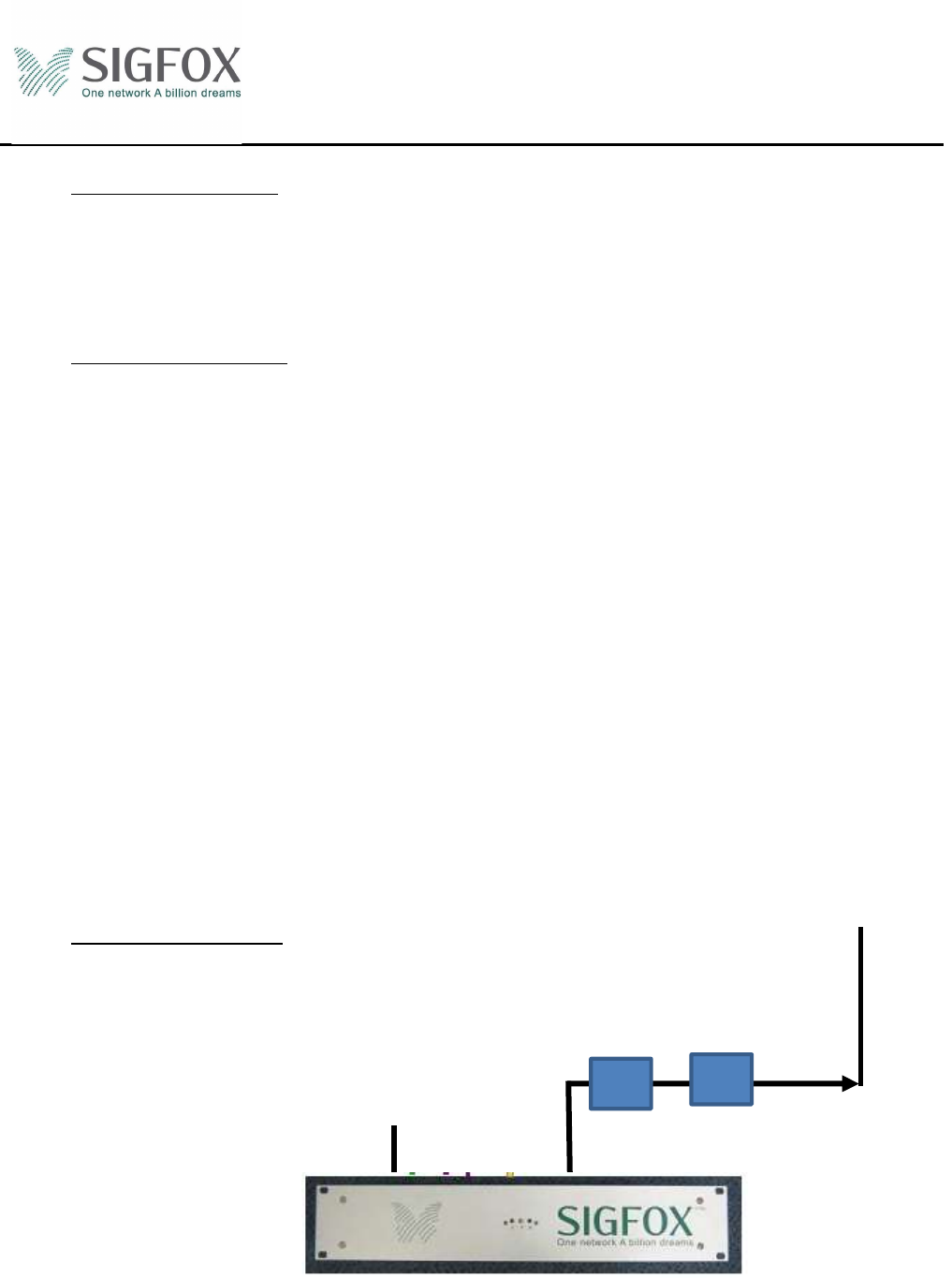
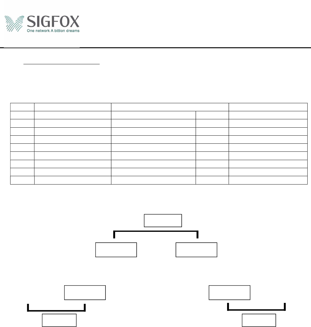
3 Installation synoptic
RF
CAVITY FILTER
(if required)
POWER SUPPLY
ANTENNA
LNA
SIGFOX SBS-T-902 v2.2 Product
Specification
Ref.:
Rev.: 2.0
Date:06/10/16
© Copyright SIGFOX. All rights reserved Page 5 of 17
4 Installation site recommendations
This base station has been developed to be installed in indoor.
It must be used with an LNA.
It can be used also with a cavity filter.
The datasheets of LNAs for 902-928MHz operation is in annex 1.
The datasheets of LNAs for 868.13MHz operation is in annex 2.
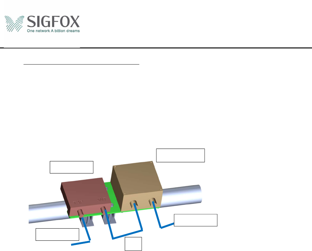
4.1 Cavity filter option
The cavity filter use is optional in some countries.
4.1.1 New Zealand
In New Zealand this base station must be installed with the cavity filter described in annex 3 on the top
of the LNA.
4.2 Antenna
This Base station was certified with an Omnidirectional Antenna with a Gain of 8dBi. Only an
omnidirectional antenna with a gain of 8dBi or less can be used.
LNA V2
Cavity Filter
Antenna
Base station
15
SIGFOX SBS-T-902 v2.2 Product
Specification
Ref.:
Rev.: 2.0
Date:06/10/16
© Copyright SIGFOX. All rights reserved Page 6 of 17
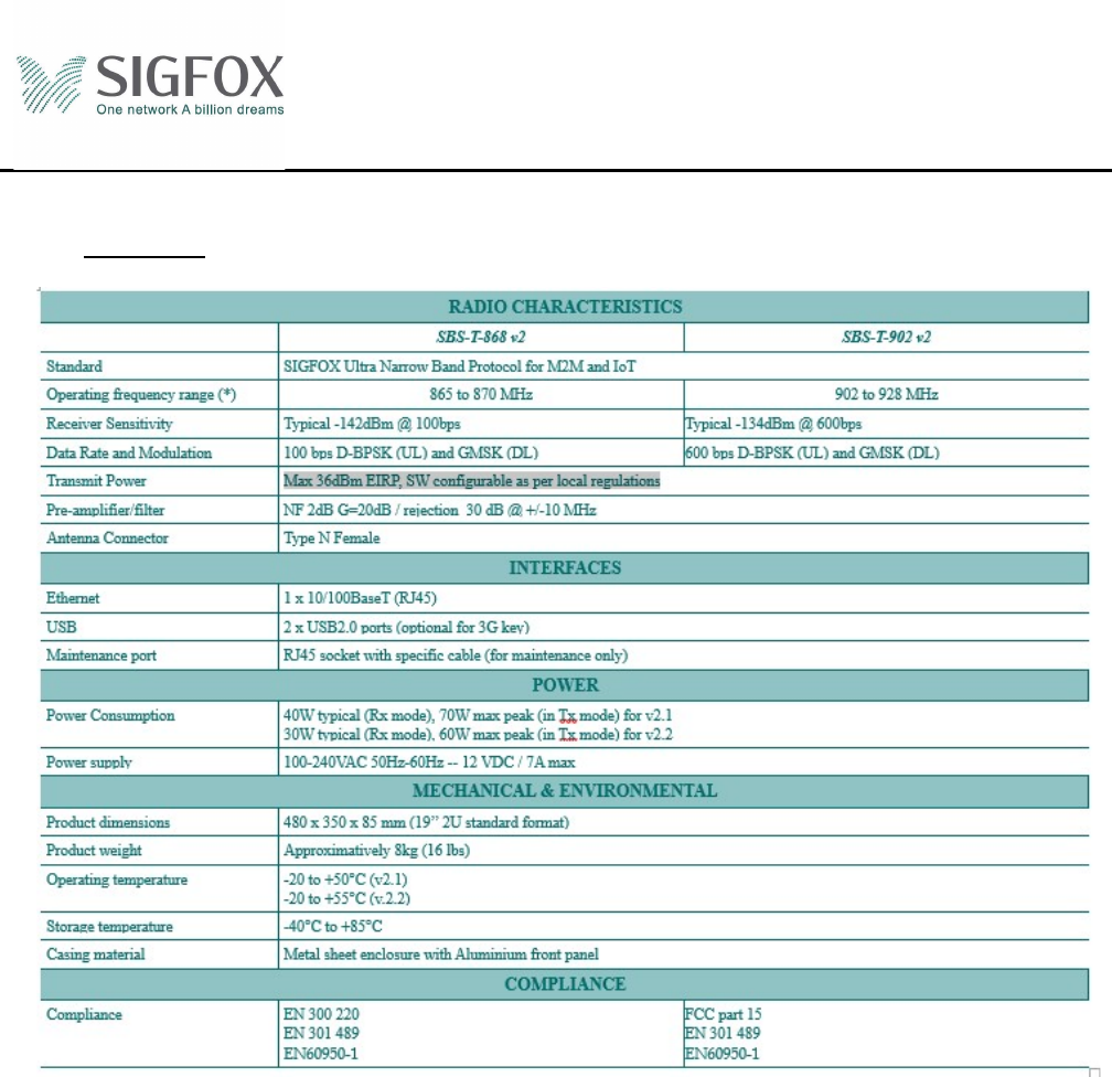
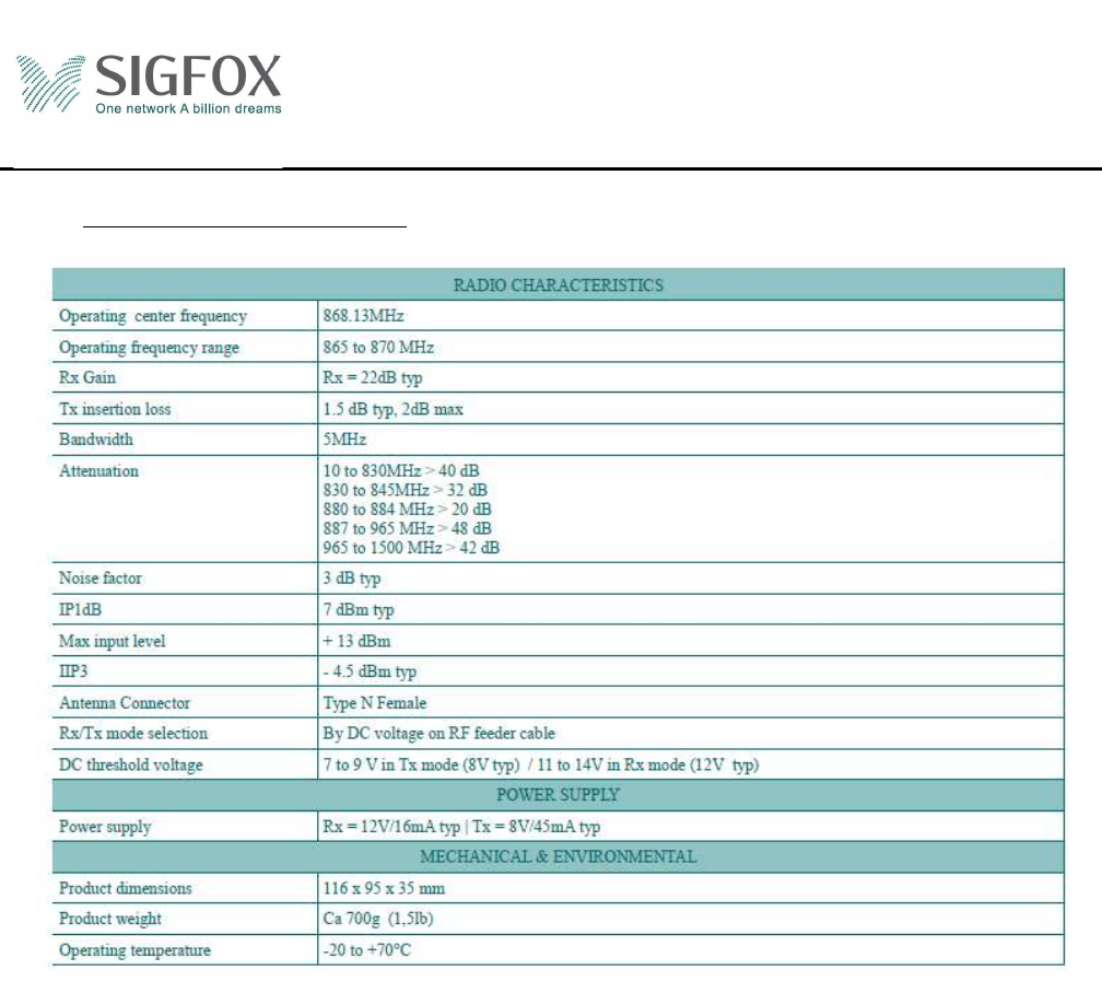
5 Datasheet

SIGFOX SBS-T-902 v2.2 Product
Specification
Ref.:
Rev.: 2.0
Date:06/10/16
© Copyright SIGFOX. All rights reserved Page 7 of 17
6 Warning statements
6.1 FCC warning statement
This device complies with Part 15 of the FCC Rules and with Industry Canada licence-exempt RSS standard(s).
Operation is subject to the following two conditions:
(1) this device may not cause harmful interference, and
(2) this device must accept any interference received, including interference that may cause
undesired operation.
Changes or modifications made to this equipment not expressly approved by (manufacturer name)
may void the FCC authorization to operate this equipment.
This equipment complies with FCC radiation exposure limits set forth for an uncontrolled
environment. End users must follow the specific operating instructions for satisfying RF exposure
compliance. This transmitter must not be co-located or operating in conjunction with any other
antenna or transmitter.
This equipment should be installed and operated with minimum distance of 20 cm between the
radiator and your body.
This equipment must be professionally installed. The installer is responsible for ensuring that the
proper antenna is employed so that the limits in part 15 are not exceeded.
Only the antennas approved by SIGFOX must be used. The antennas may not be modified. The
antenna must not be co-located or operating in conjunction with any other antenna or transmitter. No
additional antenna must be used.
NOTE: This equipment has been tested and found to comply with the limits for a Class B digital device,
pursuant to Part 15 of the FCC Rules. These limits are designed to provide reasonable protection against
harmful interference in a residential installation. This equipment generates, uses and can radiate radio
frequency energy and, if not installed and used in accordance with the instructions, may cause harmful
interference to radio communications. However, there is no guarantee that interference will not occur in a
particular installation. If this equipment does cause harmful interference to radio or television reception, which
can be determined by turning the equipment off and on, the user is encouraged to try to correct the interference
by one or more of the following measures:
Reorient or relocate the receiving antenna.
Increase the separation between the equipment and receiver.
Connect the equipment into an outlet on a circuit different from that to which the receiver is connected.
Consult the dealer or an experienced radio/TV technician for help.
6.2 IC warning statement
"Under Industry Canada regulations, this radio transmitter may only operate using an antenna of a
type and maximum (or lesser) gain approved for the transmitter by Industry Canada.
To reduce potential radio interference to other users, the antenna type and its gain should be so
chosen that the equivalent isotropic radiated power (e.i.r.p.) is not more than that necessary
for successful communication.
This device complies with Industry Canada licence-exempt RSS standard(s). Operation is subject to
the following two conditions:
(1) this device may not cause interference, and
(2) this device must accept any interference, including interference that may cause undesired
operation of the device."
SIGFOX SBS-T-902 v2.2 Product
Specification
Ref.:
Rev.: 2.0
Date:06/10/16
© Copyright SIGFOX. All rights reserved Page 8 of 17
This equipment should be installed and operated with minimum distance of 20 cm between the radiator and
your body.
Conformément à la règlementation d'Industrie Canada, le présent émetteur radio peut fonctionner avec une
antenne d'un type et d'un gain maximal (ou inferieur) approuvé pour l'émetteur par Industrie Canada.
Dans le but de réduire les risques de brouillage radioélectrique a l'intention des autres utilisateurs, il faut
choisir le type d'antenne et son gain de sorte que la puissance isotrope rayonnée équivalente (p.i.r.e.) ne
dépasse pas l'intensité nécessaire à l'établissement d'une communication satisfaisante.
Le présent appareil est conforme aux CNR d'Industrie Canada applicables aux appareils radio exempts de
licence. L'exploitation est autorisée aux deux conditions suivantes :
(1) l'appareil ne doit pas produire de brouillage, et
(2) l'utilisateur de l'appareil doit accepter tout brouillage radioélectrique subi, même si le brouillage
est susceptible d'en compromettre le fonctionnement
Cet équipement est conforme aux limites d'exposition aux rayonnements IC établies pour un environnement
non contrôlé. Cet équipement doit être installé et utilisé avec un minimum de 20 cm de distance entre la source
de rayonnement et votre corps.
7 Electrical connection
The base station must be installed with a power point with the electrical protection according to the
standards.
In case the Base station is connected to mains by its electrical cable, the electrical plug must be easily
reachable in order to remove the cable.
In case the electrical plug is not easily reachable it is mandatory to have a circuit breaker system easily
accessible for any technician in order to switch off completely the installation.
8 Battery
Attention: there is a risk of explosion if the battery is replaced by an incorrect type battery
9 Earthing
Earthing all components is extremely important. The reasons are:
- Protection against lightning strikes;
- Evacuation of static electricity in the cables and equipment.
The coaxial cable must be connected to ground of the tower by at least two earthing kits (in line with the
coaxial cable) at two locations on the tower at the top and bottom.
Base station earth point is marked with following symbol:
SIGFOX SBS-T-902 v2.2 Product
Specification
Ref.:
Rev.: 2.0
Date:06/10/16
© Copyright SIGFOX. All rights reserved Page 9 of 17
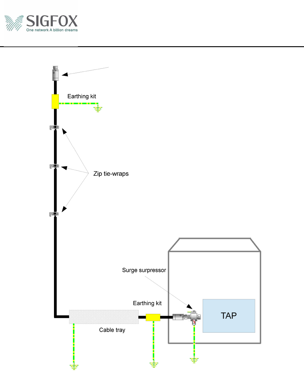
9.1 Earthing the base station
In order to protect the station, it must be earthed with a G/Y 6mm2 wire (or AWG9).
First you need to insert a grower washer or a lock washer and a grounding lug into a hexagon socket screw
M4x10. And then you must screw it into the hole provided for this purpose on the side of the station. The
correct tightening torque is of 2.2 N.m. If needed, you can bend the lug to ease the insertion of the wire.
N male connector
Earthing kit
Zip tie-wraps
Cable tray
TAP
Surge surpressor
Earthing kit
SIGFOX SBS-T-902 v2.2 Product
Specification
Ref.:
Rev.: 2.0
Date:06/10/16
© Copyright SIGFOX. All rights reserved Page 10 of 17
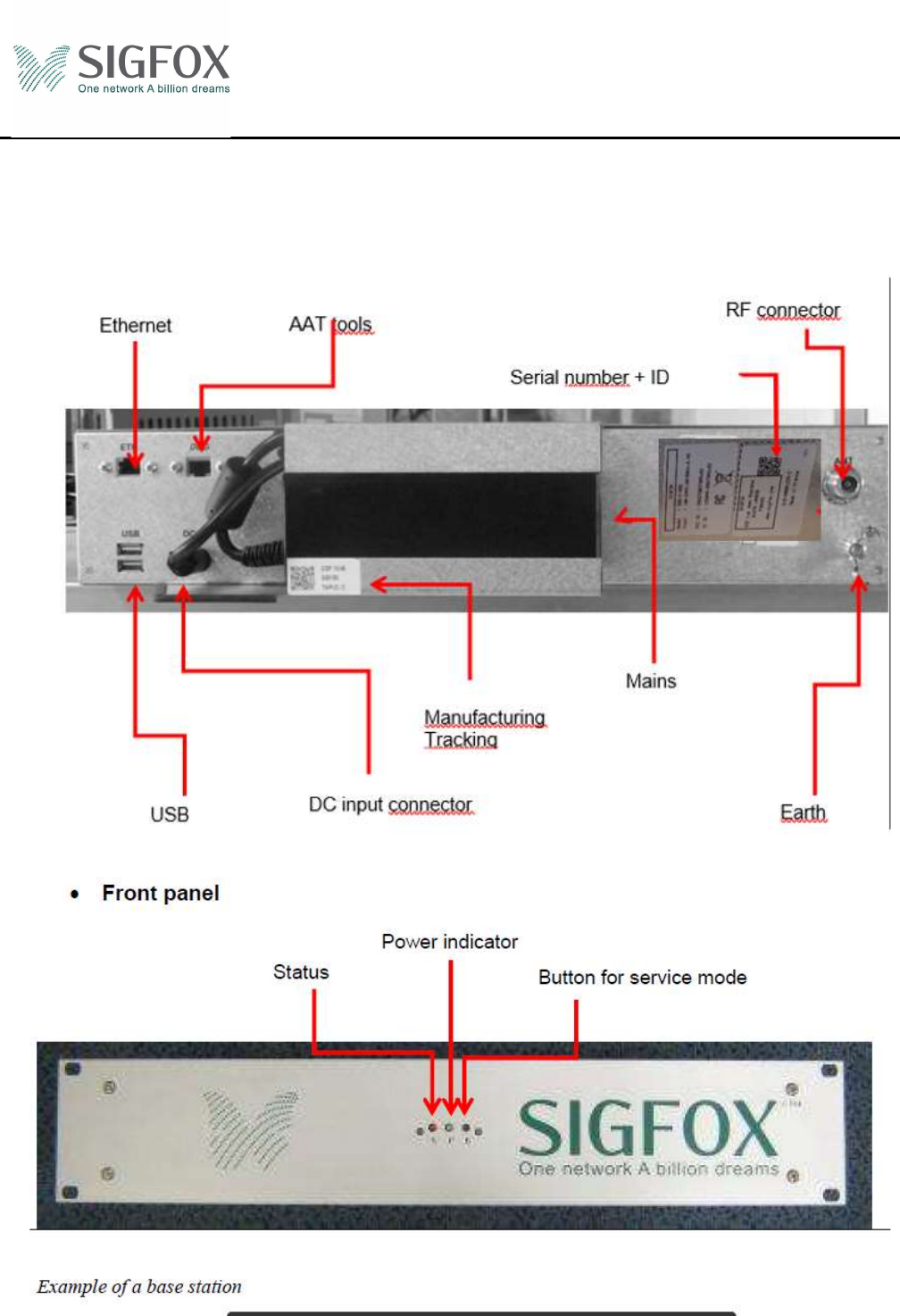
DEL Status
Electrical connection on the rear panel
Example of base station

SIGFOX SBS-T-902 v2.2 Product
Specification
Ref.:
Rev.: 2.0
Date:06/10/16
© Copyright SIGFOX. All rights reserved Page 11 of 17
Green Led « Power » :
Green Led lights => The base station is ON (TRANSFOX and PC are ON).
Green Led Off => The base station is OFF (TRANSFOX and PC are OFF).
Green Led Flash => The base station will restart or shutdown (after 60 sec max).
Red Led « Status »:
Red Led lights => operational Base station
Red Led Off => Runtime not initialize
Red Led Flash slowly => Runtime initialize but internet not active
Red Led Flash rapidly => VPN not connected
Push button:
Base station ON : long presses on the push button (>5sec until or flashing green LED) => Shutdown
the base station after 60sec maximum
Base station ON : short presses on the push button => Reboot the base station after 60 sec
Base station OFF : short presses on the push button => Instant start base station
SIGFOX SBS-T-902 v2.2 Product
Specification
Ref.:
Rev.: 2.0
Date:06/10/16
© Copyright SIGFOX. All rights reserved Page 12 of 17
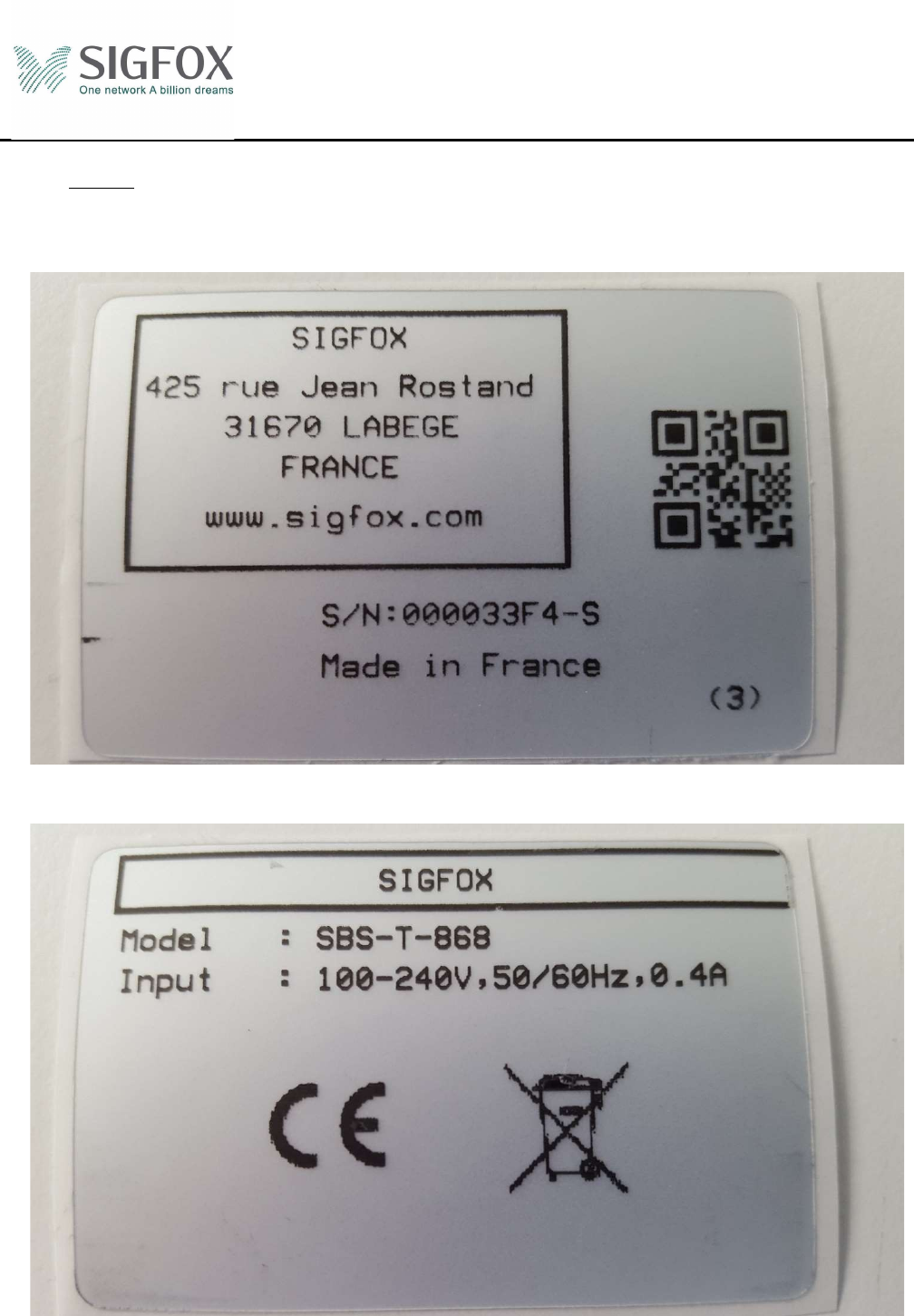
10 Labels
10.1 SIGFOX Identification
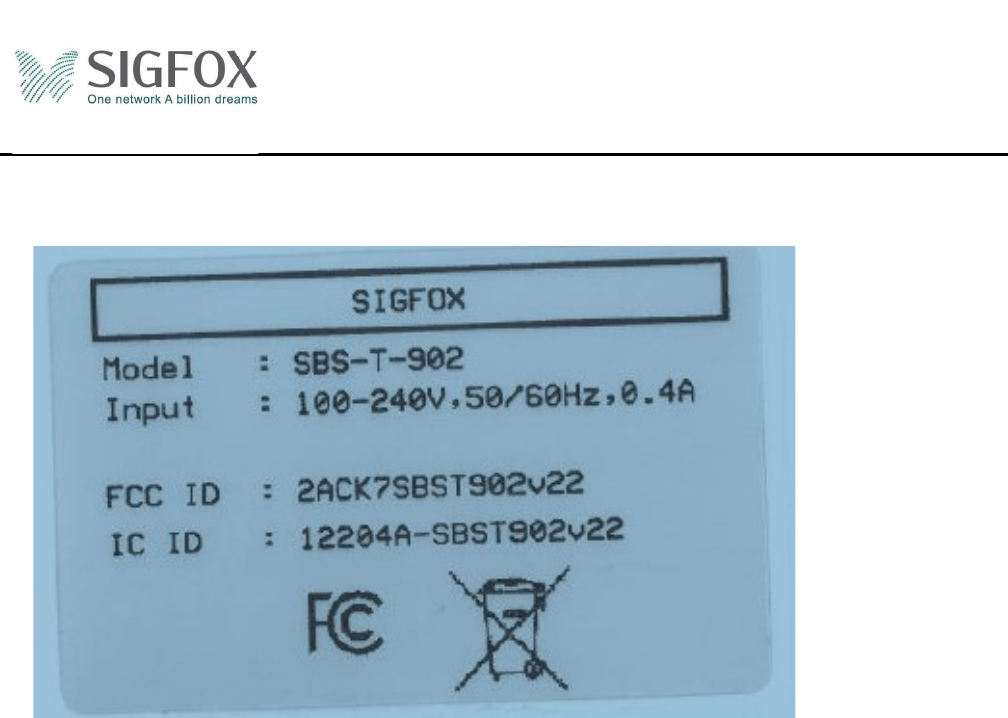
10.2 CE
SIGFOX SBS-T-902 v2.2 Product
Specification
Ref.:
Rev.: 2.0
Date:06/10/16
© Copyright SIGFOX. All rights reserved Page 13 of 17
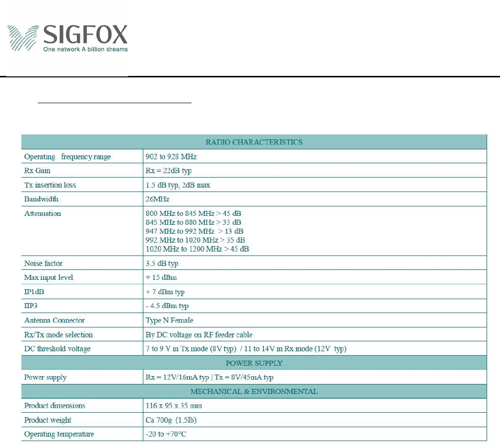
10.3 FCC
SIGFOX SBS-T-902 v2.2 Product
Specification
Ref.:
Rev.: 2.0
Date:06/10/16
© Copyright SIGFOX. All rights reserved Page 14 of 17
11 Annexe 1: LNA 902-928MHz
SIGFOX SBS-T-902 v2.2 Product
Specification
Ref.:
Rev.: 2.0
Date:06/10/16
© Copyright SIGFOX. All rights reserved Page 15 of 17
12 Annexe 2: LNA 868.13MHz
SIGFOX SBS-T-902 v2.2 Product
Specification
Ref.:
Rev.: 2.0
Date:06/10/16
© Copyright SIGFOX. All rights reserved Page 16 of 17
13 Annexe 3: Cavity filter
13.1 Electrical Specification
REQ Parameter Specification Remark
1.1 Center Frequency 922.5 MHz
1.2 Bandwidth 4 MHz
1.3 Insertion Loss 1,8 @ 923,2MHz dB typ In band
1.4 Ripple 0.5 dB max
1.5 Rejection 1 45@500~916.5MHz dBc min
1.6 Rejection 2 35@928~1500MHz dBc min
1.7 Return loss 18 dB min
1.8 Power Handing 40 dBm
1.9 Impedance 50 ohm
13.1.1 Summary
2 dB
35 dBc
45 dBc
F :920,5M
Hz
F :924.5M
Hz
F :916.5M
Hz
F :928MHz
SIGFOX SBS-T-902 v2.2 Product
Specification
Ref.:
Rev.: 2.0
Date:06/10/16
© Copyright SIGFOX. All rights reserved Page 17 of 17
13.2 Mechanical specification
REQ Parameter Specification Remark
2.1 Input Connect N – Female
2.2 Output Connect N – Female
2.3 Environment IP 65
2.4 Operation Temp -40 to +70 °C
2.5 Storage Temp -55 to +105 °C
2.6 Weight 850 gr max
2.7 Dimension ( W*L*H ) 134 x 82 x 49 mm max
2.8 Mounting hole 94 x 73.7 ( M4x0.7) mm
2.9 ROHS Yes
2.10 Finish Black painting
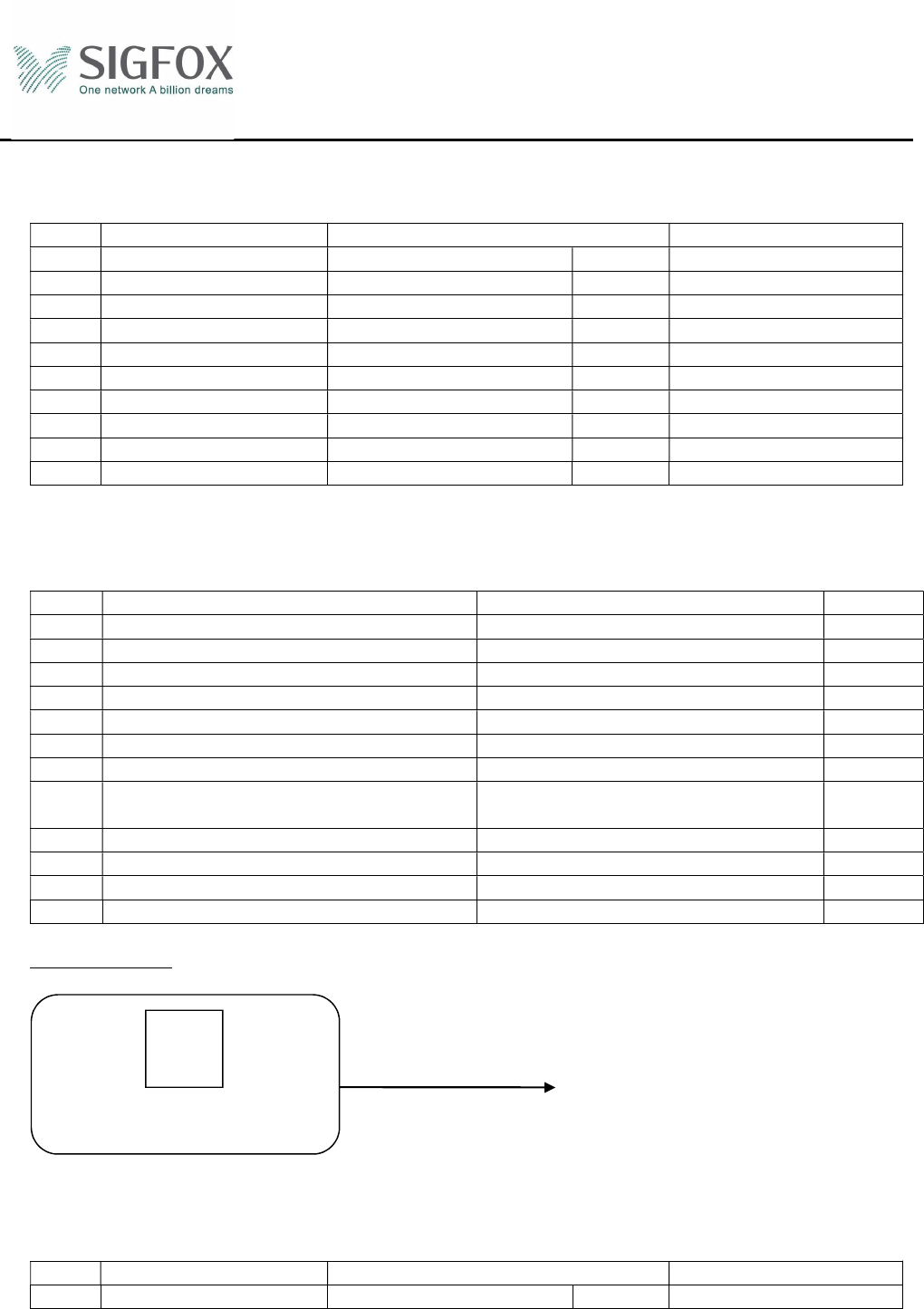
13.3 Label Specification
REQ Parameter Specification Remark
3.1 Label contains a QR code or barcode
3.2 Information in the QR code or the barcode “Manufacturer_name”
3.3 Information in the QR code or the barcode Part number written as “P/Nxxxx”
3.4 Information in the QR code or the barcode Serial number written as “S/Nxxxx”
3.5 Textual information written on the label “Manufacturer_name”
3.6 Textual information written on the label Part number written as “P/Nxxxx”
3.7 Textual information written on the label Serial number written as “S/Nxxxx”
3.8 Textual information written on the label Central frequency – Revision of the
product specification
3.9 Maximum dimension ( W*D ) 40 mm * 25 mm
3.10 Label material White glossy polyester
3.11 Print technology Thermal transfer
3.12 Label position Centered on the bottom face of the filter
Example of label:
13.4 Test report Specification
REQ Parameter Specification Remark
4.1 Frequency response Yes Per serial number
QR
code or
barcode
Information read from
the QR code or barcode
Manufacturer_name-P/Nxxxx-S/Nxxxx
Manufacturer_Name
Central frequency – Product specification revision
P/Nxxxx-S/Nxxxx