UNITEK TECHNOLOGY DX01 Body Worn Camera User Manual
SHENZHEN UNITEK TECHNOLOGY CO., LTD Body Worn Camera
User manual
Foreword
Thank you for purchasing DX01 body worn camera. Please read
this manual carefully before use and keep it for future reference.
Assertion
The Company reserves the final right to interpret the contents given
in the manual, and the contents are subject to change without
further notice. This manual is prepared only for users' reference.
The Company is committed to continuously improving customer
operation experience, and the real object shall prevail in case the
product disaccords with the manual.
Safety information
To use the product, please read carefully and learn about the
following safety measures.
Never try to open the housing of the products since only
authorized maintainers are allowed to maintain the products.
Body worn camera may show a temperature rise after it works
for a long time, and that is really not a fault.
Use only the attachments provided by the manufacturer.
Slam into the product artificially, submerge the complete
machine, or place the product in a hot environment higher
than 60 degrees for a long time.
The Company will assume no responsibility for any damages
to the product caused by the practices above.
DX01 User Manual
TABLE OF CONTENTS
SECTION I DESCRIPTION OF COMPONENTS ............................................. 3
SECTION IIBASIC OPERATION .................................... 3
2.1 STARTUP ......................................................................................................... 4
2.2 VIDEO RECORDING ......................................................................................... 4
2.3 PHOTO TAKING ............................................................................................... 5
2.4 AUDIO RECORDING ......................................................................................... 5
2.5 INFRARED NIGHT VIEWING ............................................................................. 6
2.6 PLAYBACK ...................................................................................................... 6
2.7 INTERPHONE SPEECH TRANSMISSION FUNCTION ............................................. 8
2.8 RESETTING ..................................................................................................... 8
2.9 VIDEO RESOLUTION RATIO .............................................................................. 8
2.10 PHOTO-TAKING RESOLUTION RATIO .............................................................. 8
2.11 SEGMENTATION TIME .................................................................................... 8
2.12 MOTION DETECTION FUNCTION ................................................................... 9
2.13 INDICATOR STATE ......................................................................................... 9
2.14 VOICE BROADCAST ...................................................................................... 9
2.15 LANGUAGE ................................................................................................... 9
2.16 AES ENCRYPTION FUNCTION (OPTIONAL) ................................................... 9
SECTION IIIINSTALLATION AND USE OF MANAGEMENT SOFTWARE
(BASIC EDITION).................. ............................................................................... 11
3.1 OVERVIEW OF SOFTWARE .............................................................................. 11
3.2OPERATING SYSTEM ....................................................................................... 11
3.3INSTALLATION OF DRIVER .............................................................................. 11
3.4 OPEN THE MANAGEMENT SOFTWARE ............................................................ 15
3.5 OPERATING INSTRUCTIONS FOR THE MANAGEMENT SOFTWARE .................... 15
SECTION IVCHARGING MANAGEMENT .................................................... 20
SECTION V TROUBLE SHOOTING AND SOLUTIONS ............................... 20
Attachment1 RoHS Ingredient List of China................................21
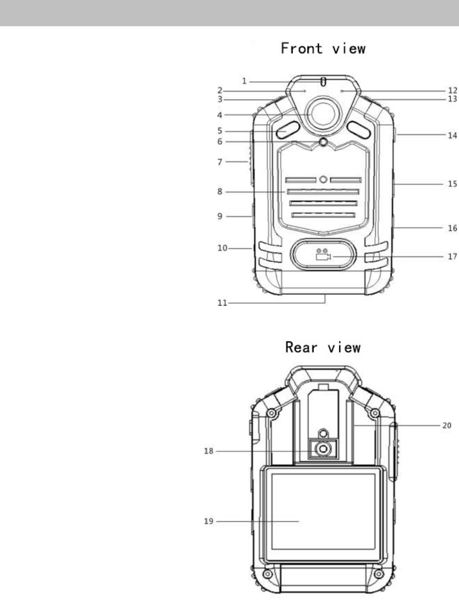
Section I Description of Components
1) Status indicator lamp
2) Local microphone
3) Photo takingkey
4) Lens
5) Infrared lamp
6) Infrared induction device
7) Talkback key
8) Speaker
9) Menu key
10) Switch key
11) Talkback interface/data interface/charging interface
12) Talkback microphone
13) Audio recording key
14) AV IN/USB interface
15) IMP key
16) Playback key
17) Video recording key
18) Reset key
19) Screen
20) Crocodile clamp interface
Section II Basic Operation
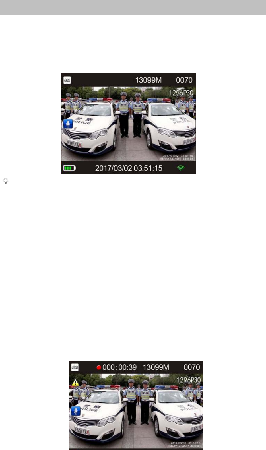
2.1 Startup
Push the power key to start up the machine, and push and hold the
key for 2s to allow the system to automatically access the preview
mode.
Note: 1.The top of LCD screen shows from left to right the
image resolution, free space, the number of shot files,
and video resolution in sequence.
2.The bottom of LCD screen shows the battery
capacity, current time and WIFI icon (optional).
2.2 Video recording
The system will automatically access the preview mode after the
machine is started up. The system starts audio video recording once
the video recording key is pushed. The machine can take a candid
photograph and automatically saves it in JPG format if the photo
taking key is pushed in process of video recording. The system
gives a “Ticktack”, stops video recording, and automatically saves
the video taken in H.264 code format if the video recording key is
pushed once again.

Note: 1. The status indicator lamp gets red and blinks in
process of video recording.
2. The top of LCD screen shows in sequence the photo
taking format, video recording status indication, free
space, the number of shot files, and video recording
format.
3. The bottom of LCD screen on the first line shows the
battery capacity, current time and WIFI icon (optional).
4. In the video recording mode, press the IMP key to
mark theimportant file. In the preview mode, long press
the IMP key to activate/deactivate the WIFI mode
(optional).
2.3 Photo taking
The system automatically accesses the preview mode after startup.
The operator may push the photo taking key to take a photo, a “Zap”
is given, and the photo taken is automatically saved in JPG format.
2.4 Audio recording
In the preview mode, operator pushes the recording key, a
“Ticktack” is given, and audio recording is started; and pushes the
recording key once more, a “Ticktack” is given, audio recording is
stopped, and the file is automatically saved in WAV format.

2.5 I
n
The
amb
i
2.6
P
2.6.1
In th
mod
e
ke
y
t
pres
s
(Fi
gu
Acc
e
pla
yb
pla
yb
pla
yb
susp
e
cont
i
pla
yb
Note: In a
u
g
ets
y
ellow
a
LCD screen
b
n
frared ni
g
h
t
machine can
ent bri
g
htnes
s
Note: 1. On
c
ma
y
automat
i
P
la
y
back
Selectin
g
a
fi
e preview m
o
e
(Fi
g
ure 1).
P
t
o scroll the
t
s
the pla
y
bac
k
u
re 2). Press t
h
Fi
g
ure 1
e
ss the pla
y
b
a
b
ack ke
y
to a
c
b
ack ke
y
onc
e
b
ack ke
y
wh
i
e
nd the pla
yb
nue pla
y
bac
k
b
ack ma
y
ret
u
u
dio recordin
a
nd blinks, a
n
b
links.
t
viewin
g
automaticall
y
s
;
c
e the infrare
d
i
call
y
g
et bla
c
fi
le t
y
pe to be
p
o
de, press the
P
ress the aud
i
y
pe of file t
o
k
ke
y
a
g
ain to
h
e menu ke
y
t
a
ck thumbnail
c
cess the full
s
e
more to star
t
i
le video an
d
b
ack, pushin
g
k
, and push
i
u
rn to the pre
v
g
mode, the
n
d a red dot i
n
y
turn on inf
r
d
lamp is tur
n
c
k and white.
p
la
y
ed back
playback ke
y
i
o recordin
g
k
o
be pla
y
ed t
o
enter the thu
m
t
o return to th
e
s of video an
s
creen pla
y
b
a
t
pla
y
in
g
bac
k
d
audio files
the pla
y
bac
k
i
n
g
the men
u
v
iew mode;
W
status indic
a
n
the top left
r
ared mode
a
n
ed on, the i
m
y
to enter the
k
e
y
or the ph
o
o
the left or r
i
m
bnail pla
y
b
a
e
preview mo
d
Fi
g
ure 2
d audio files,
a
ck mode, an
d
k
the files. P
u
are pla
y
ed
b
k
ke
y
once
m
u
ke
y
in p
r
W
hen pla
y
bac
k
a
tor lamp
corner of
a
s per the
m
a
g
e tone
pla
y
back
o
to takin
g
ig
ht, then
a
ck mode
d
e.
push the
d
push the
u
shin
g
the
b
ack may
m
ore ma
y
r
ocess of
k
is over,

the machine may automatically return to the thumbnail playback
mode.
Note: Pushing the photo taking key while video files are
played back allows the machine to implement fast backward
playback, and pushing the recording key allows the machine
to implement fast forward playback.
2.6.2 Playing back the image files
After selecting the image file in the thumbnail playback mode,press
the playback key to enter the full-screen playback mode. Press the
audio recording key or photo taking key to scroll to the previous or
next file. Push the menu key to return to the preview mode.
Fi
g
ure 3
2.6.3. Playing back IMP files
After selecting the IMP file in the playback mode, press the
playback key to enter the IMP playback mode. Press the audio
recording key or photo taking key to scroll to the previous or next
file and press the playback key to play it in full screen.
Note: During video recording, the operator may push once the
IMP key and mark the important file, or push and hold the
IMP key in preview mode to switch on/off the WIFI mode.
2.6.4 Exiting from the playback
Push the menu key in full screen playback mode to return to the

preview mode.
2.7 Interphone speech transmission function
Connect one end of the interphone connecting line to the interphone
interface of the body worn camera, connect the other end to an
interphone; true up the interphone, and implement talkback
function by operating the speech transmission key, such that the
body worn camera can serve as an on-shoulder microphone.
Note: 1. Before connecting the analog radio, please connect
the body worn camera first.
2.Please select the correct cable for different intercoms.
2.8 Resetting
Push the reset key if resetting is required.
Note: The operation may unlikely result in missing or
damages to file data.
2.9 Video resolution ratio
Operator may set up the video recording resolution ratio of the
body worn camera.
Select"1296P30:2304×1296(30)","1080P30:1920×1080(30)","720
P60:1280×720(60)","720P30:1280×720(30)"or"480P30:848×480(
30)", and then press the menu key to exit.
2.10 Photo-taking resolution ratio
Operator may set up the photo-taking resolution ratio of body
worn camera.
Select"33M:7696X4329","21M:6108X3440","16M:5376X3024",
"12M:4838X2722","5M:3226X1814"or"4M:2688X1512",andthen
press the menu key to exit.
2.11 Segmentation time
Operator may set up the video recording segmentation time of the
body worn camera.
Select "5 min", "10 min", "15 min", "25min" or "OFF", and then
press the menu key to exit.
2.12 Motion Detection Function
Open the function through the menu such that the machine can
automatically turn on video recording or photo taking once
collision or swinging reaches the triggering status.
2.13 Indicator State
Open the function through the menu to allow the machine to give
prompt by status indicator lamp at startup.
2.14 Voice Broadcast
Open the function through the menu to allow the machine to give
voice prompt at video recording.
2.15 Language
Select the language prompt through the menu: Chinese and English.
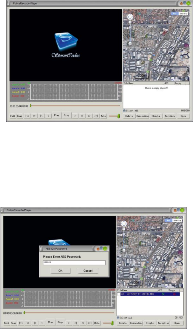
2.16 AES Encryption Function (Optional)
The global pioneer AES128 recording file encryption algorithm is
able to provide a strong security protection for your data.
When playing an AES-encrypted file in the body worn camera, an
AES icon will be shown in the video playback menu and IMP
playback menu. To play this file with any other device, it is
required to use the CarRecorderPlayer which is supplied with
product. A password must be entered before playing any
AES-encrypted file and the default initial password is 123456.
Note: The file of CarRecorderPlayer is contained in the CD
supplied with the product. When clicking it to use, you will be
prompted to install ffdshow and LAVFilters programs. Please
download and install these programs.
2.16.1 Click the CarRecorderPlayer icon in the CD to call up the
main interface of CarRecorderPlayer.
2.16.2 Click the "Open" button in the lower right corner of the
software to open the file to be played. Then a dialog box requiring
password input will be popped out on the screen. Enter the default
password "123456" (the password can be modified by using the
body worn camera management software) to play the file.
2.16.3 This player can also perform functions such as "full screen",
"snapshot", "play" and "stop".

Section IIIInstallation and Use of Management Software (Basic
Edition)
3.1Overview of Software
DX01 body worn camera management software (hereinafter
referred to as “management software”) features advantages of high
confidentiality and tampering proof of evidence files, etc., and
supports password modification, time automatic synchronization
and other functions.
Note: The version number of management software goes upon
the software presented on the supporting compact disc.
3.2Operating System
The software supports the operating systems: Windows 7 and
higher.
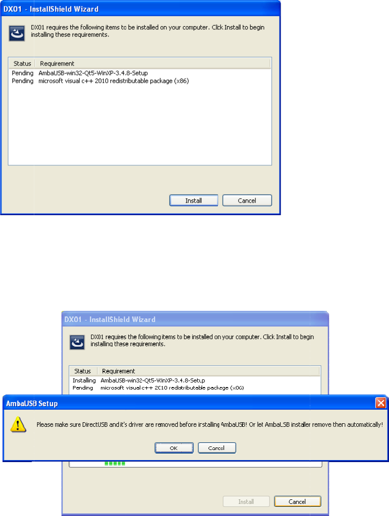
3.3Installation of Driver
You have to install the driver before you use the management
software. The installation method is described below:
3.3.1 Running the driver
Insert the CD supplied with the body worn camera into CD-ROM
driver of the host computer. Open the CD and run the installer .
Select the language "Simplified Chinese" and click "OK".
3.3.2
To i
n
3.3.3
out.
F
3.3.4
Installin
g
th
e
n
stall the driv
e
When instal
l
F
low the pro
m
To install A
m
e
drive
r
e
r, click "Inst
a
l
in
g
the drive
r
m
pt and click
"
m
baUSB driv
e
a
ll".
r
, a prompt
w
"
OK" to conti
e
r, click "Nex
t
w
indow will b
e
nue.
t
".
e
popped

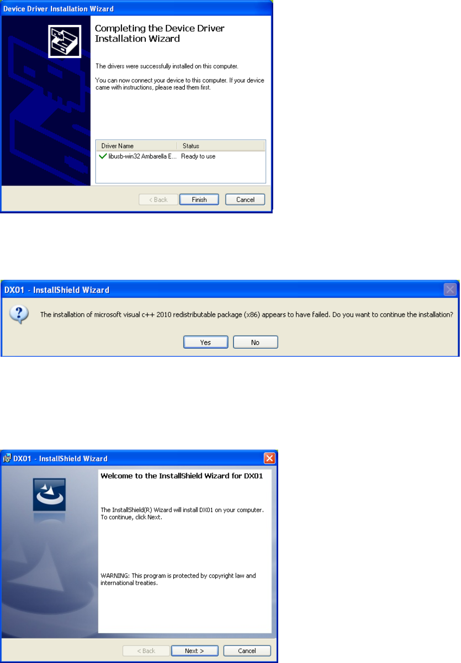
3.3.5 To install the device driver, click "Next".
3.3.6 The driver is now installed successfully,click “Done”.
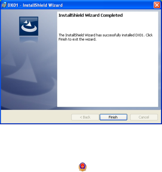
3.3.7 To install the system driver, click "Yes".
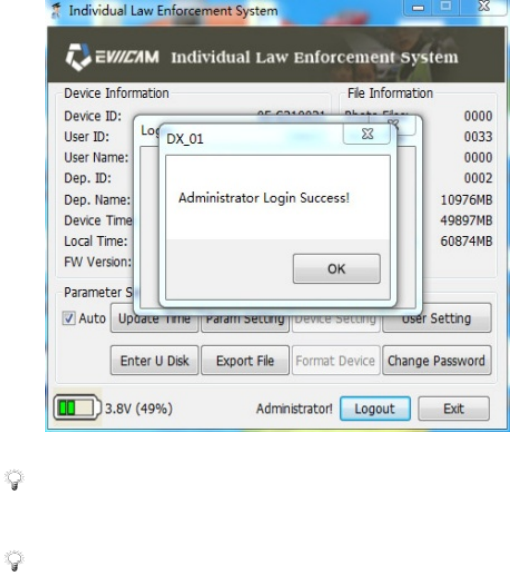
3.3.8 To install DX01 installshield wizard, click “Next”.
3.3.9 DX01 installshield wizard is now installed successfully, click
“Done”.
3.4 Open the management software
Click on the icon on the desktop or in the start menu to run.
3.5 Operating instructions for the management software
Run the management software after the body worn camera is
connected with the host computer via an USB cable.
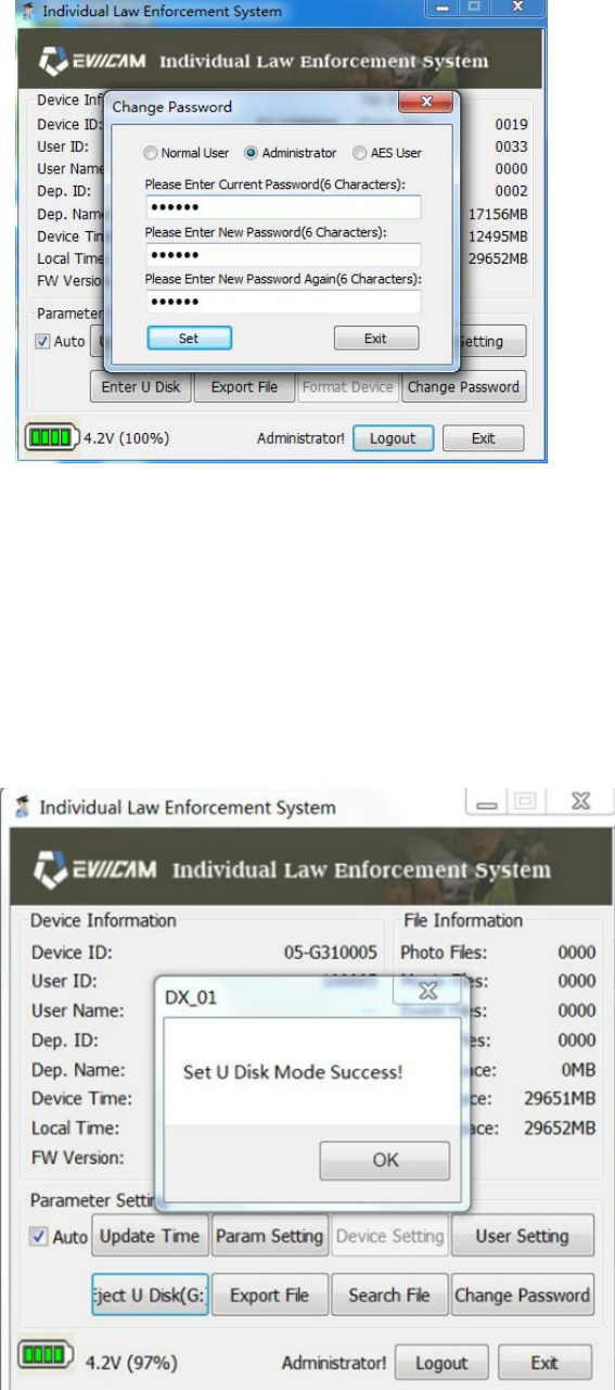
3.5.1Logging in with password
Click the “Login” button on the body worn camera screen. Select
the Normal User and enter the initial password "123456", or select
"Administrator User" and enter the initial password "888888". Then
click the “Login” button in the password input window to log in the
system. To operate the management software, enter the password
first.
Note: 1. The password can only be a 6-place number
comprising only numerals or characters.
2. A normal user is only authorized to use two parameter
setting options, "EnterU Disk",and"Change Password". Click
the "EnterU Disk" button to display "Export File", "Search
File" and "Change Password". In addition to the above 3
options, an administrator user can also access the “Update
Time", "User Setting" and "Parameter Setting" options.
3.5.2 Modifying a password
The password of body worn camera can be modified.
Click the “ChangePassword” to implement password modification.
Type in a correct old password, type in the new password twice,
clickthe“Set”,and a prompt “ChangeNormal User/Administrator
Password Success” is displayed.
3.5.3 Removable disc
In the removable disc mode, internal data files on the body worn
camera may be accessed.
Click the “EnterU Disk” button, see a new removable disc in “My
computer”, and allow the body worn camera to access removable
disc mode.
3.5.4 Searching a file
Click "Search File" to pop up the "Search&Export" dialog box.
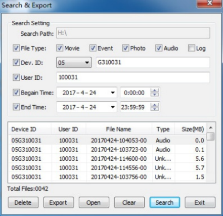
Press the "Search" button after setting the file type, device code,
user code, start time and end time respectively. All the data found
according to the preset conditions will be displayed on the screen.
Now you can delete, export or open any file, or clear the current
screen and exit.
3.5.5 Setting the parameters
Click "Parameter Setting" to pop up the "Parameter Setting" dialog
box in which the "Device Parameter" and "Export Parameter" can
be set respectively. The "Device Parameter" include the
"MovieSize", "Photo Size", "Pre-Record", "Delay Record”,
“MoiveSound”, “IRMode”, “LCD Off " and "PowerOff" options;
while the "Export Parameter" include the "Export to Local" and
"Export to FTP" options. After setting the parameters, press "Set"
to save and exit.
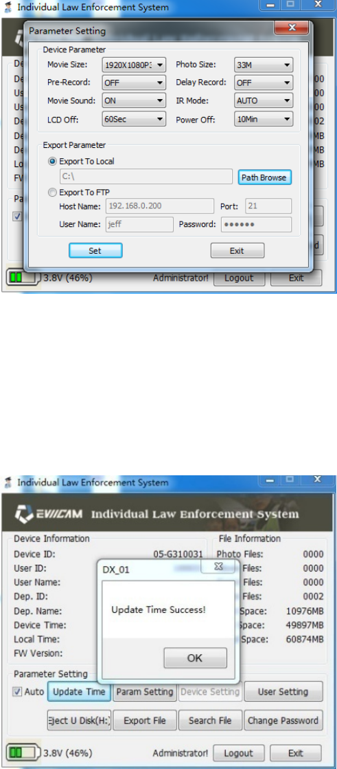
3.5.6 Synchronizing the time
Click the “UpdateTime”, the machine gives a prompt “Update Time
Success!”, and body worn camerawill automatically synchronize
with the system time of upper computer.
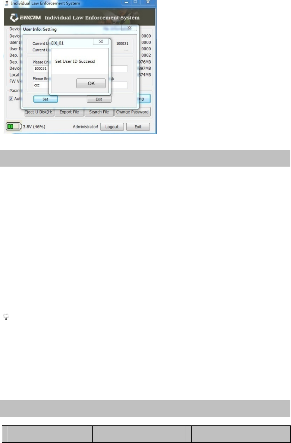
3.5.7 User information
Click the “User Setting” to pop up a dialog box “User Info.Setting”
displaying the code and name of current user, type in the new user
code and new user name, and click the “Set” to display a prompt
“Set User ID Success!”.
Section IVCharging Management
4.1 Battery charging
The body worn camera is provided with built-in rechargeable
batteries. When low battery occurs, the body worn camera gives a
sound for prompting, and an icon prompt will also be shown on the
screen.
Power adapter charging: Connect the body worn camera to power
adapter for charging, the status indicator lamp remains red in
process of charging, and it goes out when full charging is achieved.
Charging takes about 6 hours.
Note: 1. It is recommended to charge the batteries in shutdown
mode.
2. Charge the batteries once every 3 months during long-term
non-use so as to avoid failure of the batteries.
Section V Trouble shooting and Solutions
Symptom Reason Solution

Impossible to start
The battery power
is insufficient
Fully charge the
batteries using a power
adapter
Display incorrect
time/date
Time displayed on
body worn camera
is inaccurate
Access file
management system to
set up the time over
again
Photo taking/video
recording obtains
blurring and unclear
images
Lens is dirty
Clean the lens using
clean flannelette
The recorder is not
recognized when it is
connected to the
management system
USB cable is inserted
improperly
Type in an incorrect
password
Reinsert the USB
Check whether the
typed-in password is
correct
Power adapter fails to
charge the batteries
Poor contact to the
power cord
Power plug is
loosened
Check whether the
body worn camera and
power adapter for
good contact
Check and insert the
plug properly
Accessory 1 RoHS Ingredient List of China
Names and contents of hazardous substances or elements
entrained by the product:
Poisonous and harmful substance or element

Component
name
Lead
(Pb)
Mercury
(Hg)
Cadmium
(Cd)
Sexavalent
chrome
(Cr)
Polybrominated
Biphenyls
(PBB)
PBDE
Housing
body
○ / / / / /
Key plating ○ / / / / /
LCD
screen
○ / / / / /
Attachment
wires
× / ○ / / /
Lens
devices
× / ○ / / /
Resistance × / / / / /
Circuit
board
/ ○ ○ ○ ○ ○
Battery ○ / ○ / / /
○: Indicating that contents of toxic hazardous substances in all homogeneous materials of
the component are below the limits specified in SJ/T11363-2006.
×: Indicating that the content of the toxic hazardous substance in one type of
homogeneous material of the component is higher than the limits specified in
SJ/T11363-2006.
/: Indicating that the toxic hazardous substance is not detected in the component.
Note: Up to 90% of components of the product are made of non-harmful
environment-friendly materials, and the components containing toxic hazardous
substances are applied in the product since people fail to have the toxic substances or

elements substituted due to the global technology development level constraints.
FCC STATEMENT
This device complies with Part 15 of the FCC rules. Operation is
subject to the following two conditions: 1) this device may not
cause harmful interference, and 2) this device must accept any
interference received, including interference that may cause
undesired operation.
Changes or modifications not expressly approved by the party
responsible for compliance could void your authority to operate the
equipment.
NOTE: This equipment has been tested and found to comply with
the limits for a Class B digital device, pursuant to Part 15 of the
FCC Rules. These limits are designed to provide reasonable
protection against harmful interference in a residential installation.
This equipment generates uses and can radiate radio frequency
energy and, if not installed and used in accordance with the
instructions, may cause harmful interference to radio
communications. However, there is no guarantee that interference
will not occur in a particular installation. If this equipment does
cause harmful interference to radio or television reception, which
can be determined by turning the equipment off and on, the user is
encouraged to try to correct the interference by one or more of the
following measures:
Reorient or relocate the receiving antenna.
Increase the separation between the equipment and receiver.
Connect the equipment into an outlet on a circuit different from
that to which the receiver is connected.
Consult the dealer or an experienc ed radio/TV technician for
help.