USA Alo Branch DJ-X2000T Wide Range Scanning Receiver User Manual 2000448 FCC
USA Alinco Branch Wide Range Scanning Receiver 2000448 FCC
Manual

COMPANY NAME: ALINCO, INC.
EUT: DJ-X2000T
WORK ORDER NUMBER: 2000448
FCC ID: EUG DJ-X2000T
Scanning Receiver Certification Report Page 57 of 65
APPENDIX G:
INSTRUCTION MANUAL
WIDE RANGE SCANNING RECEIVER
Instruction Manual
Thank you for purchasing the ALINCO
receiver. The DJ-X2000 instruction
manual contains important safety and
operating instructions. Read this manual
carefully before using the product.
DJ-X2000
MODE
AUTO MW
INTELLIGENT
RECEIVER
DJ-X2
MIC
SCRT PRIO
REC
CTCSS
F TUNE
A-B S
M NAME
TF
SKIP
STEP
ATT
SET
POWERRX/ST
PMS
VFOMR MW
A B
SET
KL
3
6
9
8
0
5
2
1
4
CLR
ENT
MIC
SCN
RF C
HELP
7
MONI
F
SRCH
LAMP
SQL VOL
DOWN UP
CLN
S P

1
Features
The Alinco DJ-X2000 is a professional multifunctional receiver which covers a
wide band of radio media from the low-frequency band (LF) to ultrahigh-
frequency (UHF) band. It has the following features.
1. Wide frequency range The DJ-X2000 covers the wide frequency range from
0.1 to 2149.999950 MHz.
2. Three basic modes The DJ-X2000 has three basic modes: Dual VFO,
Memory (MR), and Scan Programming (PMS). The
modes can be switched by one-touch operation.
3. Memory capacity Memory function allows you to program the
frequencies up to 2000 channels. (40 ch ×50 banks)
4. Scanning Various kinds of scan are available: Program scan
(PMS), Memory scan, Mode-select scan, VFO scan,
VFO-linked scan, and Priority scan.
5. 20 scan programs The PMS mode has a total of 20 programmable bands.
6. Channel scope The search function checks frequencies in the set
frequency steps and displays signals within a 40-
channel or 7-channel range at once.
7. Battery-save function The battery-save function automatically saves on
battery power whenever keys are not used or a signal
is not picked up for a certain amount of time.
8. Cloning You can copy the settings stored in memory from one
DJ-X2000 to another. Moreover, you can connect the
DJ-X2000 with a personal computer to copy the
settings.
9. All mode reception You can select a signal mode from AM, NFM, WFM,
LSB, USB, CW, and AUTO. When AUTO is selected,
the DJ-X2000 automatically determines the most
suitable signal mode for currently receiving frequency.
10. Channel step Channel step is selectable from 23 fixed steps, or you
can set any step between 50 Hz - 500 kHz. In addition,
the DJ-X2000 determines the most suitable channel
step for currently receiving frequency when AUTO is
selected.

2
11. Frequency editing You can copy the content of one memory channel to
another, or rename memory channels.
12. Transweeper The DJ-X2000 detects the listening microphone which
transmits a radio wave. If a listening microphone is
found, the DJ-X2000 will alert you with a display and
warning sound.
13. Recording function The DJ-X2000 records the sound of currently receiving
signal or from the microphone, and replays it. The
maximum recording time is 160 minutes.
14. Descrambler The DJ-X2000 can return scrambled voice transmission
to a normal voice reception.
15. Flash tune If there are signals around the DJ-X2000, it tunes in the
strongest frequency in a flash.
16. RF checker This function allows you to use the DJ-X2000 as a radio
frequency checker.
17. Electric field strength meter The DJ-X2000 can measure the electric field strength
and indicate it on the display.
18. Directional microphone The built-in microphone picks up the sound and
amplifies it.
19. Transceiver function The DJ-X2000 can be used as a transceiver or
transmitter using 250 MHz band.
20. Receiving FM radio in stereo The DJ-X2000 receives FM radio in stereo.
21. CTCSS decoder The DJ-X2000 decodes the CTCSS signal.
22. A/B squelch Using this function, the squelch unmutes only when the
DJ-X2000 fails to receive a modulation signal of 2300 Hz.
23. Help-navigator The Help-navigator shows how to use each function of
the DJ-X2000 on the display. Moreover, you can jump
to the setting display of currently displayed function
from the help menu, and execute the function.
24. Exceedingly sensitive antenna for HF and MF
Newly developed antenna is attached.
25. DC switching power supply DC switching power supply saves on the battery
power.
26. 2-level attenuator High (20 dB) and Low (10 dB) attenuators are
available.

3
Contens
1. Before use……………………………………………………00
1.1 Unpacking the receiver ………………………………………………00
1.2 Precautions in use ……………………………………………………00
1.3 Names of parts and their funciotns …………………………………00
1.3.1 Top, front and left side panels …………………………………………………………00
1.3.2 Rear and right panels ……………………………………………………………………00
1.3.3 Display ……………………………………………………………………………………00
1.3.4 Key pad……………………………………………………………………………………00
1.4 Setting up the DJ-X2000 ………………………………………………00
1.4.1 Attaching the antenna……………………………………………………………………00
1.4.2 Attaching the belt clip……………………………………………………………………00
1.4.3 Attaching the wrist strap…………………………………………………………………00
1.5 About the batteries ……………………………………………………00
1.5.1 Attaching the battery pack………………………………………………………………00
1.5.2 About the battery pack …………………………………………………………………00
1.5.3 Ni-Cd batterypack ………………………………………………………………………00
1.5.4 Battery low alarm…………………………………………………………………………00
2. Basic operations ……………………………………………00
2.1 POWER switch …………………………………………………………00
2.2 Volume control …………………………………………………………00
2.3 Squelch control…………………………………………………………00
2.4 Setting frequency ………………………………………………………00
2.5 Switching frequency band ……………………………………………00
2.6 Copying frequencies from one band to the other ………………00
2.7 Scanning …………………………………………………………………00
2.8 Sarching(Channel Scope) ……………………………………………00
2.9 Monitoring(Squelch OFF) ……………………………………………00
2.10 Turning backlight ON/OFF …………………………………………00
2.10.1 Turning backlight ON/OFF manually …………………………………………………00
2.10.2 Turning backlight ON/OFF based on the setting……………………………………00
2.11 Turning beep ON/OFF ………………………………………………00
2.12 Locking/Unlocking ……………………………………………………00
2.13 Setting the clock………………………………………………………00
2.13.1 Setting the OFF timer…………………………………………………………………00

4
2.13.2 Setting the ON timer …………………………………………………………………00
2.14 Basic modes …………………………………………………………00
2.14.1 VFO mode ………………………………………………………………………………00
2.14.2 PMS mode ………………………………………………………………………………00
2.14.3 MR mode ………………………………………………………………………………00
2.15 Using HELP menu …………………………………………………00
3. Other Useful Functions ……………………………………00
3.1 Functions common to all modes ……………………………………00
3.1.1 Selecting a signal mode…………………………………………………………………00
3.1.2 Setting the frequency step………………………………………………………………00
3.1.3 Attenuating interference from other cannels(ATT)……………………………………00
3.1.4 Battery Save ………………………………………………………………………………00
3.1.5 Copying data between two receivers(CLONE) ………………………………………00
3.1.6 Selecting a communication speed ……………………………………………………00
3.1.7 Selecting a language mode ……………………………………………………………00
3.1.8 Field-strength meter ……………………………………………………………………00
3.1.9 Displaying battery voltage ………………………………………………………………00
3.1.10 Setting the reception tone ……………………………………………………………00
3.1.11 Selecting the BELL mode………………………………………………………………00
3.1.12 Changing the initial message …………………………………………………………00
3.1.13 Resetting the receiver …………………………………………………………………00
3.1.14 Tuning in frequencies in the PMS/MR modes(M.TUNE)……………………………00
3.1.15 Setting scan resume condition(SCAN MODE)………………………………………00
3.1.16 Setting scan signal level ………………………………………………………………00
3.1.17 Setting the scanning pause period …………………………………………………00
3.1.18 Turning the priority function ON/OFF…………………………………………………00
3.1.19 Selecting a priority option ……………………………………………………………00
3.1.20 Setting priority signal channel…………………………………………………………00
3.1.21 Specifying a priority interval …………………………………………………………00
3.1.22 Setting search resume condition(SRCH MODE) ……………………………………00
3.1.23 Flash tune ………………………………………………………………………………00
3.1.24 Descrambler ……………………………………………………………………………00
3.1.25 CTCSS decoding function ……………………………………………………………00
3.1.26 A/B squelch ……………………………………………………………………………00
3.1.27 Transweeper ……………………………………………………………………………00
3.1.28 Recording function ……………………………………………………………………00
3.1.29 Sound pickup……………………………………………………………………………00

5
3.1.30 Transceiver function ……………………………………………………………………00
3.1.31 Directly changing the settings…………………………………………………………00
3.2 Functions in the VFO mode ………………………………………00
3.2.1 VFO link function …………………………………………………………………………00
3.2.2 Scanning between VFO's A and B(AB SCAN) ………………………………………00
3.2.3 Copying frequencies from memories to the VFO ……………………………………00
3.2.4 Copying frequencies from the PMS mode to the VFO ………………………………00
3.3 PMS mode functions …………………………………………………00
3.3.1 Programmed scan operations …………………………………………………………00
3.3.2 Setting scan pass-frequency……………………………………………………………00
3.3.3 Setting program link ……………………………………………………………………00
3.3.4 Copying scan programs…………………………………………………………………00
3.3.5 Moving a scanning program ……………………………………………………………00
3.3.6 Deleting scan programs…………………………………………………………………00
3.4 MR mode functions ……………………………………………………00
3.4.1 Memorizing frequencies…………………………………………………………………00
3.4.2 Setting the auto memory write function ………………………………………………00
3.4.3 Setting memory scan skip ………………………………………………………………00
3.4.4 Setting memory scan radio system(MODE SEL) ……………………………………00
3.4.5 Using the BANK LINK function …………………………………………………………00
3.4.6 Selecting memory channels for scanning ……………………………………………00
3.4.7 Scanning the memory channels selected in the PMR screen ………………………00
3.4.8 Copying memory banks …………………………………………………………………00
3.4.9 Copying memory channels ……………………………………………………………00
3.4.10 Moving a memory bank ………………………………………………………………00
3.4.11 Moving a memory channel ……………………………………………………………00
3.4.12 Deleting memory banks ………………………………………………………………00
3.4.13
Deleting and restoring memory channels
………………………………………………00
3.4.14 Searching for a memory tag …………………………………………………………00
4.Appendix………………………………………………………00
4.1 Specifications …………………………………………………………00
4.2 Troubleshooting ………………………………………………………00
4.3 Otpitional items…………………………………………………………00
4.4 List of Help menu items ………………………………………………00
6
How to read this manual
The following typographical and graphic conventions are used in this instruction
manual.
Bold typeface indicates titles of chapters and sections as well as messages
shown on the display.
When used to indicate displayed messages, only the part of the message that is
pertinent to the explanation is given. Actual messages may however contain
more characters.
Plain typeface text enclosed in “ ” indicates sections in this instruction manual
you should refer to for further information. Only in a few cases are quotation
marks used to identify terminology.
Note: The note icon contains additional information pertinent to product use, which
is helpful but not necessarily known.
CAUTION: The caution icon contains information which, if ignored or not
followed correctly, could result in product damage. Always read and
observe these items.

6 a
Tested to Comply
With FCC Standards
FOR HOME OR OFFICE USE
Information in this document are subject to change without notice or obligation.All
brand names and trademarks are the property of their respective owners. Alinco
cannot be liable for pictorial or typographical inaccuracies. Some parts, options
and/or accessories are unavailable in certain areas. Changes or modifications not
expressly approved by the party responsible for compliance could void the user's
authority to operate the equipment.
Copyright 2000 All rights reserved. No part of this document may be reproduced,
copied, translated or transcribed in any form or by any means without the prior
written permission of Alinco, Inc., Osaka, Japan. English Edition Printed in Japan.
NOTICE
This equipment has been tested and found to comply with the limits for a
Class B digital device, pursuant to part 15 of the FCC Rules. These limits are
designed to provide reasonable protection against harmful interference in a
residential installation. This equipment generates, uses, and can radiate radio
frequency energy and, if not installed and used in accordance with the
instruction manual, may cause harmful interference to radio communications.
However, there is no guarantee that interference will not occur in a particular
installation. If this equipment does cause harmful interference to radio or tele-
vision reception, which can be determined by turning the equipment off and
on, the user is encouraged to try to correct the interference by one or more of
the following measures:
- Reorient or relocate the receiving antenna.
- Increase the separation between the equipment and receiver.
- Connect the equipment into an outlet on a circuit different from that to which
the receiver is connected.
- Consult the dealer or an experienced radio/TV technician for help.

7
1. Before use
1.1 Unpacking the receiver
The DJ-X2000 should come with the following accessories. Check that nothing is
missing when you first open the package.
• Antenna ×1
• Charger ×1
• EBP-37N (Ni-Cd battery pack ) ×1
• Belt clip ×1
• Belt clip screws ×2
• Wrist strap ×1
• DJ-X2000 Instruction Manual (This manual) ×1
Standard accessories may differ depending on the version.
1.2 Precautions in use
• Do not use or store the receiver in dusty places, where exposed to direct
sunlight, near to sources of heat, or in other adverse environments.
• Attach the included antenna securely to the receiver.
• Use only the EDC-36 car lighter cable (with active filter) to draw power from an
automobile.
• If the receiver emits smoke or strange odors, shut power OFF immediately and
promptly contact an authorized dealer.
• Do not disassemble or tamper with the receiver. The DJ-X2000 is not warranted
for troubles or accidents resulting from unauthorized modifications, regardless
of the warranty period. Alinco dealer also reserves the right to refuse to service
the receiver in such event.
• Obtain approval from the proper authorities before using this receiver onboard
aircraft or in hospitals.
• Do not use 9.6 V or higher voltage batteries (e.g. EBP-36N).
8
1.3 Names of parts and their functions
This section describes parts by name and function.
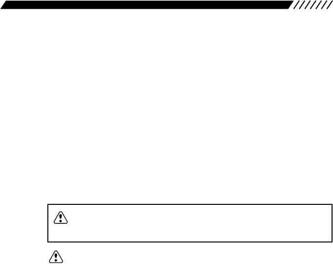
1.3.1 Top, front and left side panels
1. Dial Use to switch frequency and memory channel, to
adjust the audio volume and squelch level, and to
make other settings.
2. CLN terminal Use to clone settings between two DJ-X2000s, and
to connect with the PC editor.
3. SP terminal Connect an external speaker with amplifier or
earphone here. FM radio can be received in stereo
when stereo speakers or stereo earphones are
connected.
4. Antenna connector BNC connector. Attach the included antenna here.
1.
2.
3.
4.
5.
6.
9.
8.
7.
10.
11.
12.
13.
14.
15.
16.
17.
18.
19.
20.
MODE
AUTO MW
INTELLIGENT
RECEIVER
DJ-X2
MIC
SCRTPRIO
REC
CTCSS
F TUNE
A-B S
M NAME
TF
SKIP
STEP
ATTSET
POWER RX/ST
PMS
VFOMR MW
A B
SET
KL
3
6
9
8
0
5
2
1
4
CLR
ENT
MIC
SCN
RF C
HELP
7
MONI
F
SRCH
LAMP
SQL VOL
DOWN UP
CLN
S P

9
5. (Function) key Use this key in combination with other keys to call up
specific functions.
6. key Temporarily cancels the squelch for the duration it is
held down. Used independent of squelch level.
7. key Press to start scanning with in a 40-channel range.
Use in combination with key to start scanning in a
7-channel range.
In transceiver mode, this key is used as a PTT key.
(See "Note" below.)
8. key Turns the key backlight ON/OFF.
9. VOL/SQL key Use to adjust the audio volume and squelch level.
10. UP/DOWN key Use to set frequency, to adjust the audio volume and
squelch level, to set various settings, and to select an
item in menu display.
11. POWER switch Turns power ON/OFF.
12. Hardware reset key Press to reset all functions to their factory-settings.
However, data stored in memory is not deleted.
Settings might return to the settings when power was
turned ON the last time.
13. Busy lamp Lights green when a signal is picked up and stays lit
while the signal is alive. Lights orange when receiving
FM radio in stereo (using stereo earphones).
In Transceiver mode, lights red while transmitting.
14. Speaker Sound is produced from here.
15. key Shifts to the scan programming mode. If pressed in
combination with the key, the scan program can
be saved in memory.
16. key Engages the dual VFO mode. If pressed in
combination with the key, the frequency displayed
in the top band is copied in the bottom band.
17. key Use to access the memory. If pressed in combination
with the key, frequencies and other data can be
saved in memory.
18. Display Displays frequency, operating status and other
information pertinent to use.
19. Key pad In the VFO mode, use these keys to directly input the
frequency you want. Press in combination with the
key to access other functions.
20. Built-in microphone Use to pick up the sound and record it, or use in
transceiver mode.
Note: PTT (Press to talk) key is usually attached to a transceiver. In the DJ-X2000,
the key is used as a PTT key in transceiver mode. You can transmit a
signal while PTT key is held down, or every press of PTT key switches
between transmission and reception.
SRCH
F
F
MRMW
F
A=B
VFO
F
PMS
SET
LAMP
F
SRCH
MONI
F
10
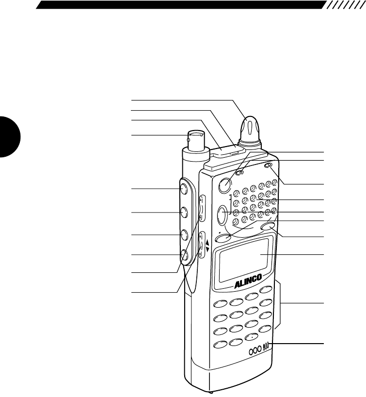
1.3.2 Rear and right panels
1. DC-IN Connect an external DC supply here (10 - 16 V).
2. Holes for attaching belt clip
Screw the included belt clip to the DJ-X2000 here.
3. Battery case lock Slide to the right to detach the battery case.
4. EBP-37N battery pack or dry cell case
The dry cell case can hold four AA batteries.
1.
2.
3.
4.
11
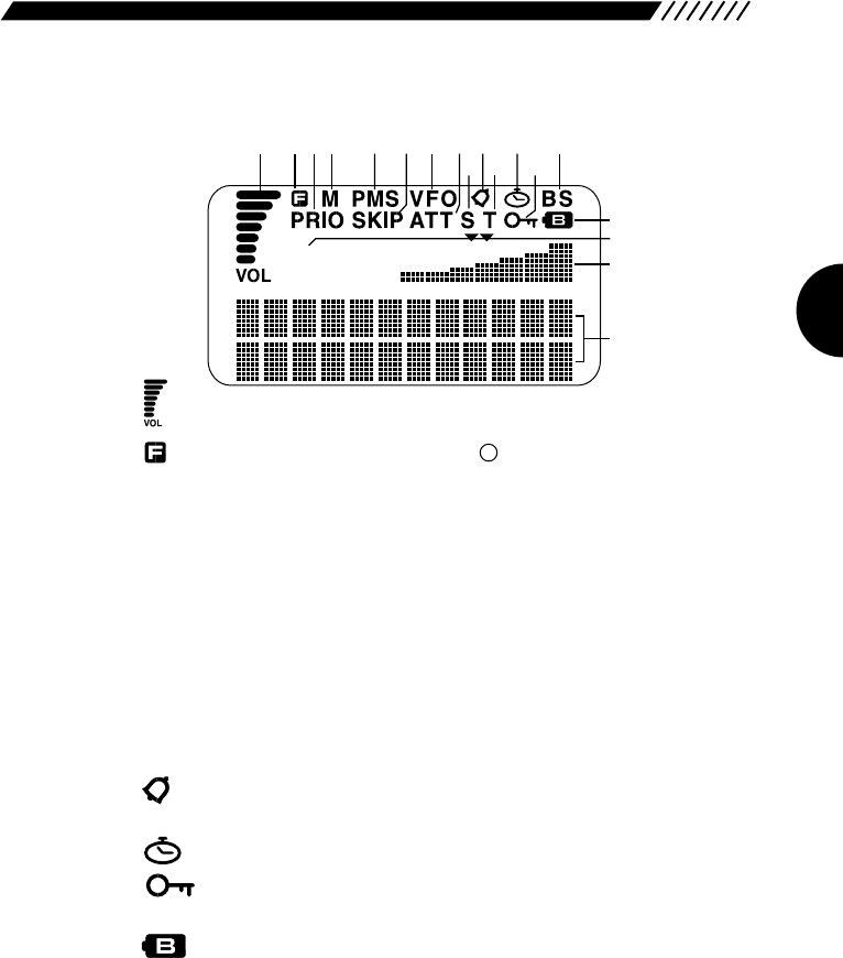
1.3.3 Display
1. Meter for displaying sound level.
2. Displayed when the key has been pressed to
indicate that you can access the subfunctions of the
keys.
3. PRIO Displayed while the priority function is ON.
4. M Displayed in the MR mode.
5. PMS Displayed in the PMS mode.
6. SKIP Displayed for memoroy channels which are skipped in
memory scans. Skip is user-set.
7. VFO Displayed in the VFO mode.
8. ATT Displayed when the attenuator is ON.
9. S Displayed when a frequency indivisible by the set
frequency step is entered.
10. Displayed when the bell function is ON.
11. T Displayed when the CTCSS decoder is ON.
12. Displayed when On-timer or Off-timer is ON.
13. Displayed while keys are locked.
14. BS Displayed when the battery-save function is ON.
15. Displayed when battery power is low. Promptly replace
the batteries if this icon is displayed.
16. AM Signal mode is displayed. When the audio volume or
squelch level is being adjusted, either of them is
displayed.
17. S-meter S-meter. Depending on settings, the time or the
channel scope setting is also displayed here.
18. Dot-matrix display This is where band, channel name and frequency are
displayed in the various modes.
F
A
M
1.
18.
2.3.4. 5. 6. 7. 8.
9.
10.12.
11. 13.
14.
15.
17.
16.
12
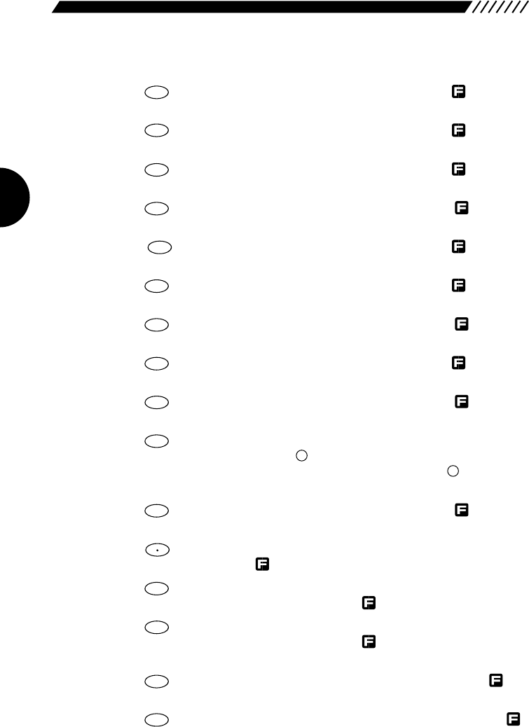
1.3.4 Key pad
1. Inputs 1. Press in combination with the key to
switch the radio band.
2. Inputs 2. Press in combination with the key to set
frequency step.
3. Inputs 3. Press in combination with the key to turn
the attenuator ON/OFF.
4. Inputs 4. Press in combination with the key to
turn the Directional microphone function ON.
5. Inputs 5. Press in combination with the key to turn
the auto memory write function ON/OFF.
6. Inputs 6. Press in combination with the key to
lock/unlock keys.
7. Inputs 7. Press in combination with the key to set
the Descrambler.
8. Inputs 8. Press in combination with the key to turn
the priority function ON/OFF.
9. Inputs 9. Press in combination with the key to set
the CTCSS decoder.
10. Clears settings. In VFO mode, press in combination
with the key to set VFO-link. In PMS and MR
modes, press in combination with the key to set
the scan pass frequency and skip channel.
11. Inputs 0. Press in combination with the key to
turn the recording function ON.
12. Inputs • (decimal point). Press in combination with the
key to set the Flash tune function.
13. Press to call up the Help-navigator. Press in
combination with the key to call up menus.
14. Press to turn the RF checker ON. Press in
combination with the key to turn the Memory
search function ON.
15. Starts scanning. Press in combination with the
key to scan between band A and band B.
16. Enters input values. Press in combination with the
key to turn the Transweeper ON.
ENT
TF
SCN
A~B S
RFC
M NAME
HELP
SET
F TUNE
0
REC
F
F
CLR
SKIP
9
CTCSS
8
PRIO
7
SCRT
6
KL
5
AUTO MW
4
MIC
3
ATT
2
STEP
1
MODE
13
1.4 Setting up the DJ-X2000
Before using your receiver, attach the included antenna securely. If wanting to
use the belt clip or wrist strap, attach them too.
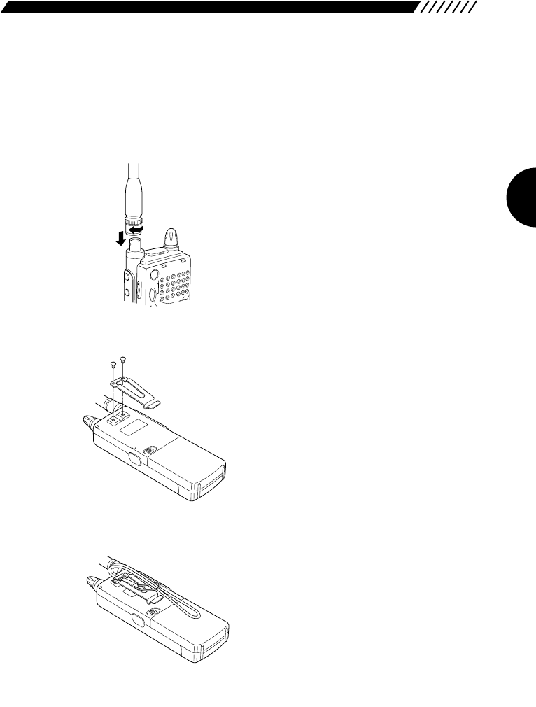
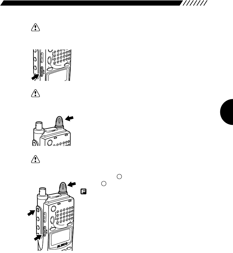
1.4.1 Attaching the antenna
Fit the base of the antenna over the
projections on the connector, press
downward and turn clockwise. Check the
antenna is securely attached.
1.4.2 Attaching the belt clip
Screw the belt clip onto the rear panel
(screws x 2). Check the clip is securely
attached before use.
1.4.3 Attaching the wrist strap
Fit the wrist strap under the belt clip and
pull it through its own loop.
POWERRX/ST
PMS
VFO MR MW
A B
SET
MONI
F
SRCH
SQL VOL
P
CLN
S P
14
1.5 About the batteries
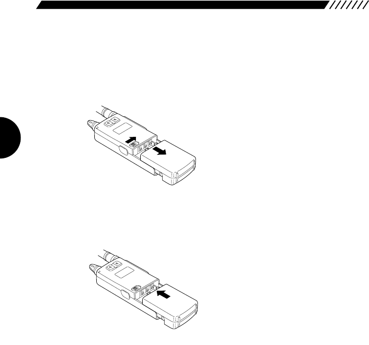
1.5.1 Attaching the battery pack
• To detach the battery pack Slide the battery pack lock on the case to
the right and pull the case downward to
detach.
• To attach the battery pack Fit the battery pack into the holes on the
DJ-X2000 and push in the direction of the
arrow until the case snaps into the place.

15
1.5.2 About the battery pack
Before using the included EBP-37N battery pack, please note the followings.
1. The battery pack is not charged before it is shipped from the factory. Charge
the pack before using the DJ-X2000 for the first time.
2. Approximately 1 hour is required to fully charge the battery pack with the
charger.
3. Charge batteries only in temperatures from 0°C to 40°C (32°F~104°F).
4. DANGER! Do not disassemble, tamper with, heat or wet the battery pack.
5. Do not short-circuit battery pack terminals. This can generate heat inside the
pack resulting in burns and/or damage to the pack.
6. Do not overcharge the battery pack. Overcharging can lead to battery
performance loss.
7. Store the battery pack in a cool, dry place where temperature is between
-20°C and 45°C(-4°F~113°F). Environments outside this range can cause
battery acid to leak and metal parts to rust.
8. The battery pack can be fully recharged approximately 300 times. When a
fully charged battery pack lasts considerably less than expected, it is time to
replace it with a fresh pack.
9. Do not throw away dead Ni-Cd battery packs. They can be recycled. Give
them to stores which accept old batteries.
10. Do not charge an unexhausted battery pack repeatedly. It may shorten the
operating time of a battery pack.
• To prevent battery pack short-circuiting
When carrying the battery pack, be extremely careful not to short-circuit the
terminals. If short-circuited, the high surge in current could heat up the pack,
resulting in burns or fire.
1. Keep the battery pack away from metal objects such as necklaces, etc.
2. Do not keep the battery pack inside bags with metal-plated linings or wrap it in
handkerchiefs with metallic thread or print.
3. Do not leave the battery pack in proximity of electro-conductive materials or
metal objects such as nails or chains.
4. Place the battery pack in an electrically-insulated bag or wrap it in a
handkerchief before putting it in your handbag, etc.
5. Place the battery pack on an electrically-insulated mat when setting it on a flat
surface.
16
1.5.3 Ni-Cd battery pack
The supplied battery charger is designed exclusively for use with our NiCd
battery pack.
Precautions in using the charger
1. The battery charger is designed exclusively for use with our NiCd battery
pack. Never use it to recharge any other rechargeable battery or dry cell.
2. Do not use the battery charger as a power source for any appliance.
3. Do not disassemble the battery charger.
4. Do not put any metal piece or wire in the battery charger, nor short-circuit the
recharging terminals.
5. Do not use the battery charger in a location where the temperature rises high,
e.g., near a heater or under direct sunlight, or where the dust or humidity level
is high.
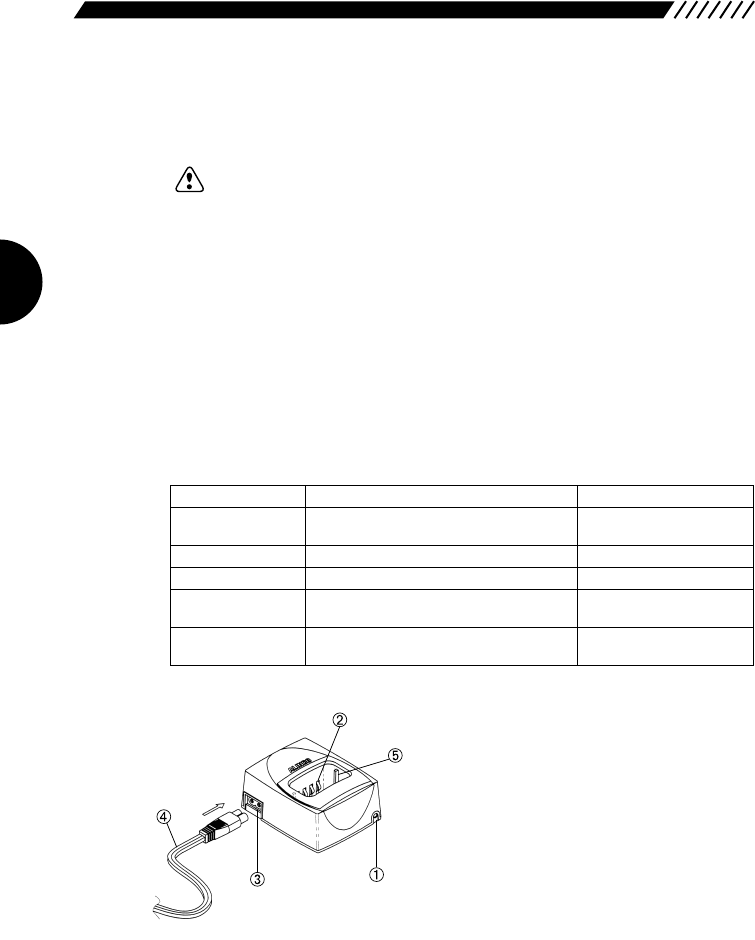
• Parts designation and function
➀Lamp
Indicates the status of the battery charger.
➁Recharging terminals
Used for recharging the battery pack.
➂AC power socket
Used to plug the AC power cord.
➃AC power cord
Used to supply AC power.
➄Guides (on the right and left sides)
Used to guide the transceiver when
inserting it into the battery charger.
Lamp status
Illuminated in red
Illuminated in green
Blinking in green
Blinking in red
Blinking alternately
in red and green
Battery charger status
Quick recharge is in progress.
Supplemental recharge is in progress.
Supplemental recharge is completed.
Supplemental recharge is in progress for
the completely discharged battery pack.
An irregular battery pack is in place.
Handling the battery pack
Leave it until it has been
recharged completely.
It may be removed.
Remove it.
Leave it until it has been
recharged completely.
Remove it immediately.
17
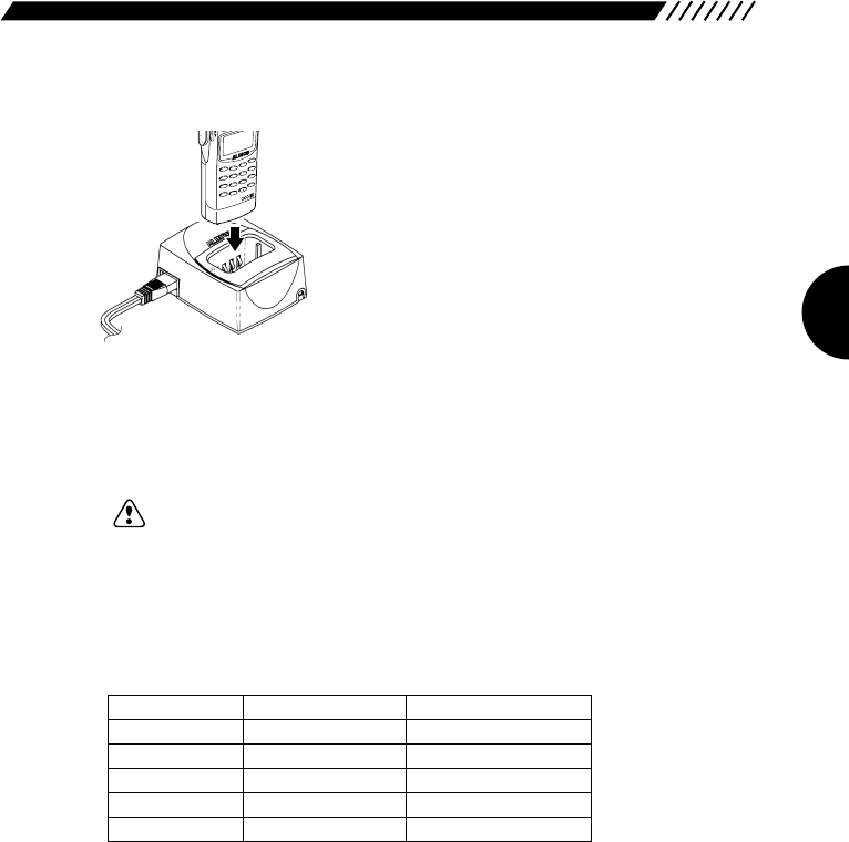
• Recharging procedure1Plug the AC power cord into the AC power
socket on the battery charger.
2Insert the battery pack being recharged, along
the guides provided on both sides of the battery
charger. The lamp will be illuminated in red, and
quick recharge will be started.
3When the quick recharge is completed, the lamp
changes its color to green, indicating that
supplemental recharge (*) has started.
4About four hours after the quick recharge has
started, the lamp starts blinking in green,
indicating that the supplemental recharge has
been completed.
Note: The supplemental recharge means recharging the battery pack with small
electric current to prevent its capacity from decreasing due to the self-
discharge. This does not overload the battery pack.
• Battery pack vs. recharging time
The battery packs applicable to each battery charger model and their
recharging time are shown below:
MODE
AUTO MW
INTELLIGENT
RECEIVER
DJ-X2
MIC
SCRTPRIO
REC
CTCSS
F TUNE
A-B S
M NAME
TF
SKIP
STEPATTSET
KL
3
6
9
8
0
5
2
1
4
CLR
ENT
MIC
SCN
RF C
HELP
7
LAMP
DOWN
Battery pack
EBP-33N
EBP-34N
EBP-35N
EBP-37N
EBP-47N
Battery capacity
4.8V 650mAh
4.8V 1200mAh
7.2V 900mAh
4.8V 700mAh
7.2V 700mAh
Recharging time
Approx. 1 hour
Approx. 1.5 hours
Approx. 1.2 hours
Approx. 1 hour
Approx. 1 hour
18
Precautions in recharging
1. Ensure that the transceiver is OFF when recharging the battery pack. The use
of the transceiver during the recharging can cause the transceiver to
malfunction.
2. The battery charger is designed to be used at an ambient temperature
between 10°C and 40°C. Avoid recharging the battery pack at any
temperature outside this range.
3. Do not repeatedly recharge the fully recharged battery pack. This can cause
the performance of the battery pack to deteriorate. The battery pack can be
recharged 500 times when it is used normally. If the life of the completely
recharged battery pack becomes markedly shorter, the battery pack is
considered to have been exhausted. Please purchase a new battery pack.
4. Do not insert the battery pack in a reverse direction.
5. When the battery pack has been recharged completely with the lamp blinking
in green, remove the battery pack from the battery charger.
6. If the battery charger is not used for a long period of time, disconnect the AC
power cord from the wall socket, and remove the battery pack from the battery
charger.
7. If you recharge the battery pack of which voltage has abnormally dropped
due to discharge, the lamp starts blinking in red and the preliminary recharge
initiates immediately after you have started recharging the battery pack.
Subsequently, the lamp will be illuminated in red, indicating that the quick
recharge has started.
8. If any irregular battery pack is set in place, the lamp will blink alternately in red
and green.
1.5.4 Battery low alarm
When batteries get low, the icon appears on the
display to the sound of a repeated siren-like alarm.
Change the batteries as soon as possible.
However, the alarm is not emitted if the beep is turned
OFF.
19
2. Basic operations
This chapter describes the basic operations for the DJ-X2000.
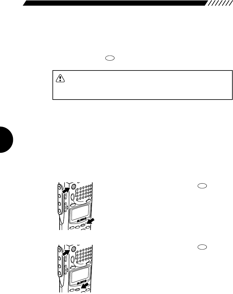
2.1 POWER switch
To turn ON/OFF the DJ-X2000, perform the following operation:
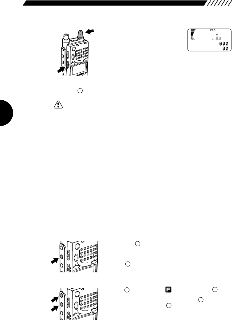
• Turning ON Hold down the POWER switch for approx. 1 second until
the message “ALINCO INTELLIGENT RECEIVER” appears
on the display.
• Turning OFF
Hold down the POWER switch until the display goes out.
Note: The message that appears on the display may be changed (see “3.1.12
Changing the initial message” on page 41).
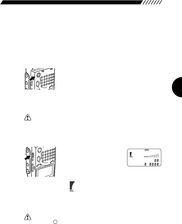
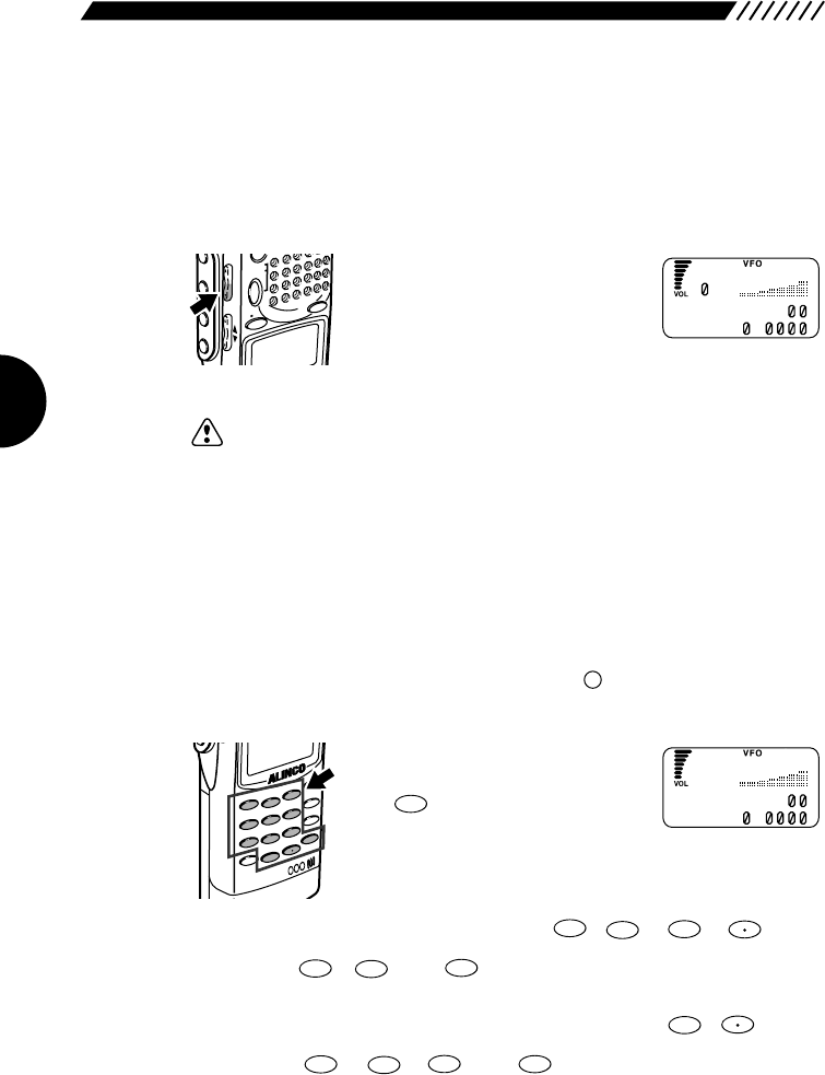
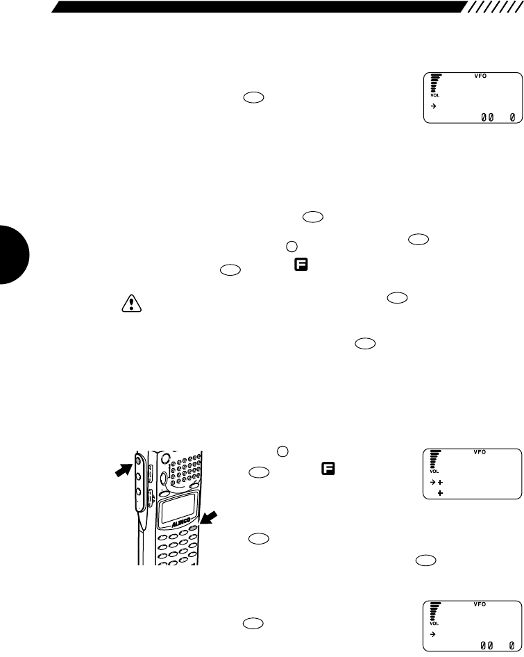
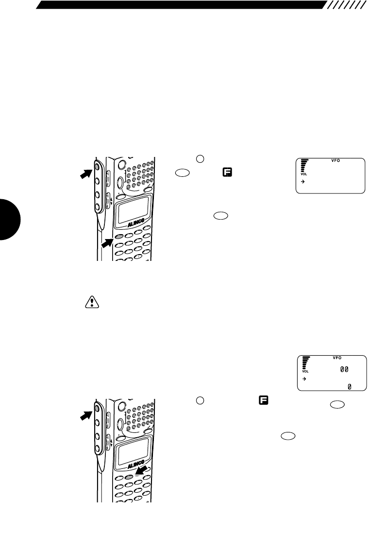
2.2 Volume control
To turn up the volume, press the
VOL key located on the left side of
the body, and then press the UP
key or turn the dial clockwise. To
turn down the volume, press the
VOL key, and then press the DOWN key or turn the dial
counterclockwise.
The bars on the display will increase/decrease with
the adjacent number changed between V00 and V32 as
you control the volume.
Note: To disengage the squelch (the mute function) temporarily, press and hold
the key on the left panel. This will enable you to set the volume setting
without changing the squelch setting (see “2.3 Squelch control” page 21).
MONI
POWER
PMS
VFOMR MW
A B
SET
MONI
F
SRCH
LAMP
SQL VOL
DOWN UP
POWERRX/ST
PMS
VFOMR MW
A B
SET
MONI
F
SRCH
SQL VOL
P
V
A 145.34
b8.
16
20
2.3 Squelch control
Squelch is used to mute the speaker noise when no signal is being received.
Squelch level can be selected between SQ0 and SQ9. Setting is made as
follows.
A squelch level can be selected from the range between S00 and S32.
To select a squelch level, press the
SQL key located on the left side of the
body, and then press the UP/DOWN
key or turn the dial. The squelch level
will be shown on the display in
accordance with the setting.
Note: • Higher squelch levels require higher signal levels to release the muting.
Set the squelch to a level at which the noise just disappears.
• The level at which to release the muting varies depending on the received
frequency even if the electric field strength remains the same. Adjust the
squelch at the most suitable level for the frequency to be received.
• If the squelch level is too high, weak incoming signals may not be heard
from the speaker.
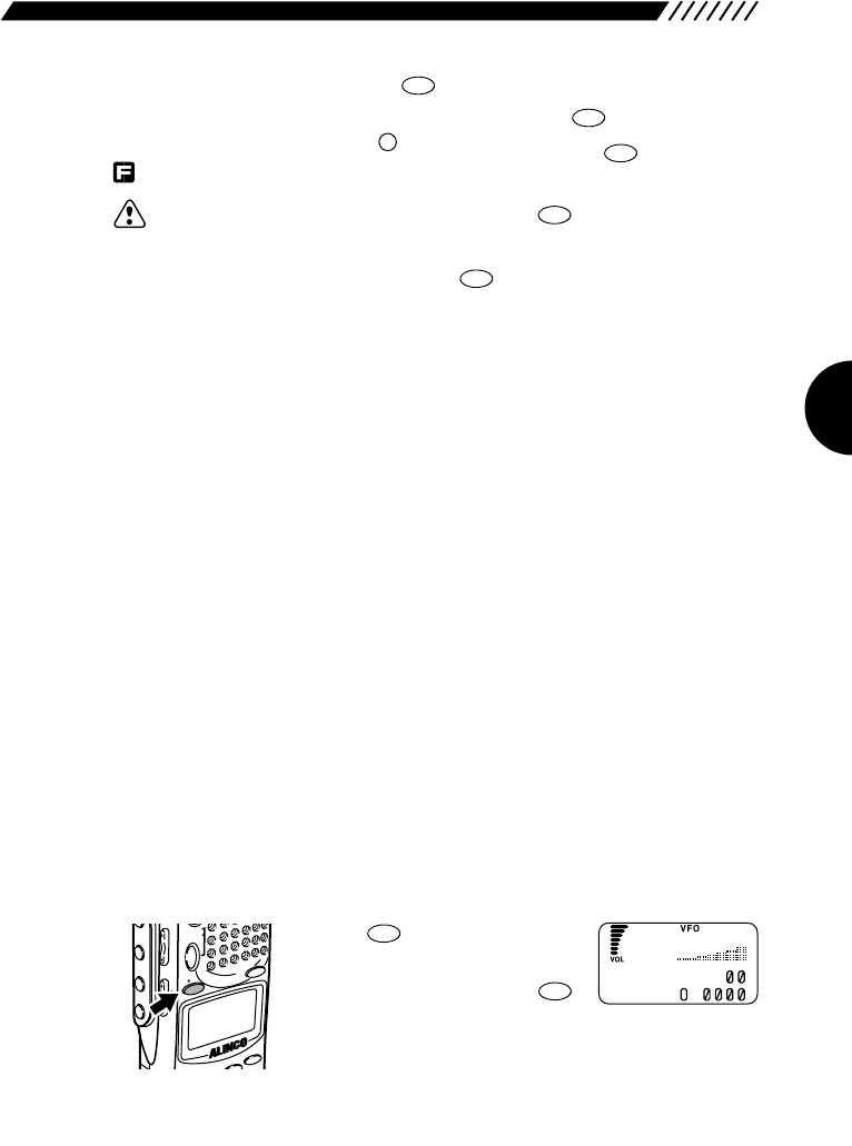
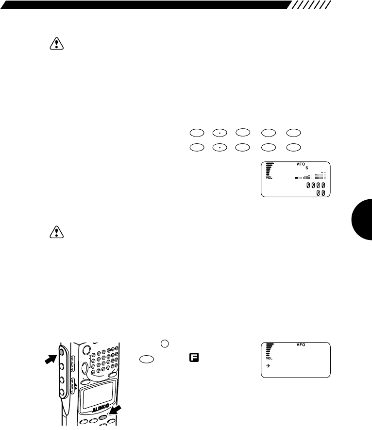
2.4 Setting frequency
Frequency can be set in any of four ways: By using the numeric keys, the
UP/DOWN key, the dial, or the combination of the key and the dial.
• Setting by numeric keys
Input the frequency directly from
the numeric keys and then press
the key.
Example 1 To set 145.3400 MHz, press the , , , ,
, , and keys in the given order.
The 00 on the end can be omitted.
Example 2 To set 0.5580 MHz (that is, 558 kHz), press the , ,
, , , and keys in the given order.
The 0on the end can be omitted.
ENT
TF
8
PRIO
5
AUTO MW
5
AUTO MW
F TUNE
0
REC
ENT
TF
4
MIC
3
ATT
F TUNE
5
AUTO MW
4
MIC
1
MODE
ENT
TF
MODE
AUTO MW
INTELLIGENT
RECEIVER
DJ-X2
MIC
SCRTPRIO
REC
CTCSS
F TUNE
A-B S
M NAME
TF
SKIP
STEPATTSET
KL
3
6
9
8
0
5
2
1
4
CLR
ENT
MIC
SCN
RF C
HELP
7
DO
F
PMS
VFOMR MW
A B
SET
MONI
F
SRCH
LAMP
SQL VOL
DOWN UP
S
A145.34
b8.
5
N
A 145.34
b8.
FM
21
Note: If you enter any frequency that cannot be divided by the set frequency step,
“S” appears on the display.
• Setting with the UP/DOWN key
For higher frequencies, press the UP key. For lower
frequencies, press the DOWN key. The frequency will
increase/decrease in the set frequency steps.
Note: For changing the frequency steps, see “3.1.2 Setting the frequency steps”
(page 33).
• Setting from the dial
For higher frequencies, turn the dial clockwise. For lower
frequencies, turn it counterclockwise. The frequency will
increase/decrease in the set frequency steps.
Note: For changing the frequency steps, see “3.1.2 Setting the frequency steps”
(page 33).
• Setting with the combination of the key and the dial
Press the key, and then press the UP/DOWN key with
shown on the display. An under-bar will appear at
the digit of 100, 10, or 1 MHz. Now turning the dial allows
you to change the number at that digit. Pressing the
UP/DOWN key shifts the digit at which the number can be
changed.
F
MODE
M NAME
STEPATTSET
POWERRX/ST
PMS
VFOMR MW
A B
SET
3
HELP
MONI
F
SRCH
LAMP
SQL VOL
DOWN UP
CLN
S P
F
POWERRX/ST
S
F
CLN
S P
PMS
VFOMR MW
A B
SET
MONI
F
SRCH
LAMP
SQL VOL
DOWN UP
22
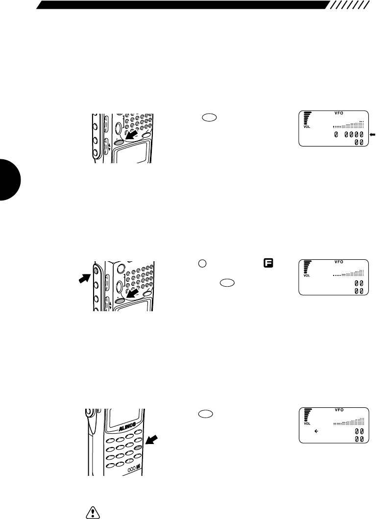
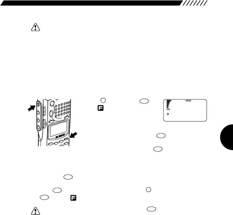
2.5 Switching frequency band
The DJ-X2000 uses a dual VFO system, so that a frequency change can be done
smoothly by inputting a new frequency on the second band in advance. The
frequency currently being monitored is displayed next to the capital letter on the
top line of the display. Frequency band can be switched as follows.
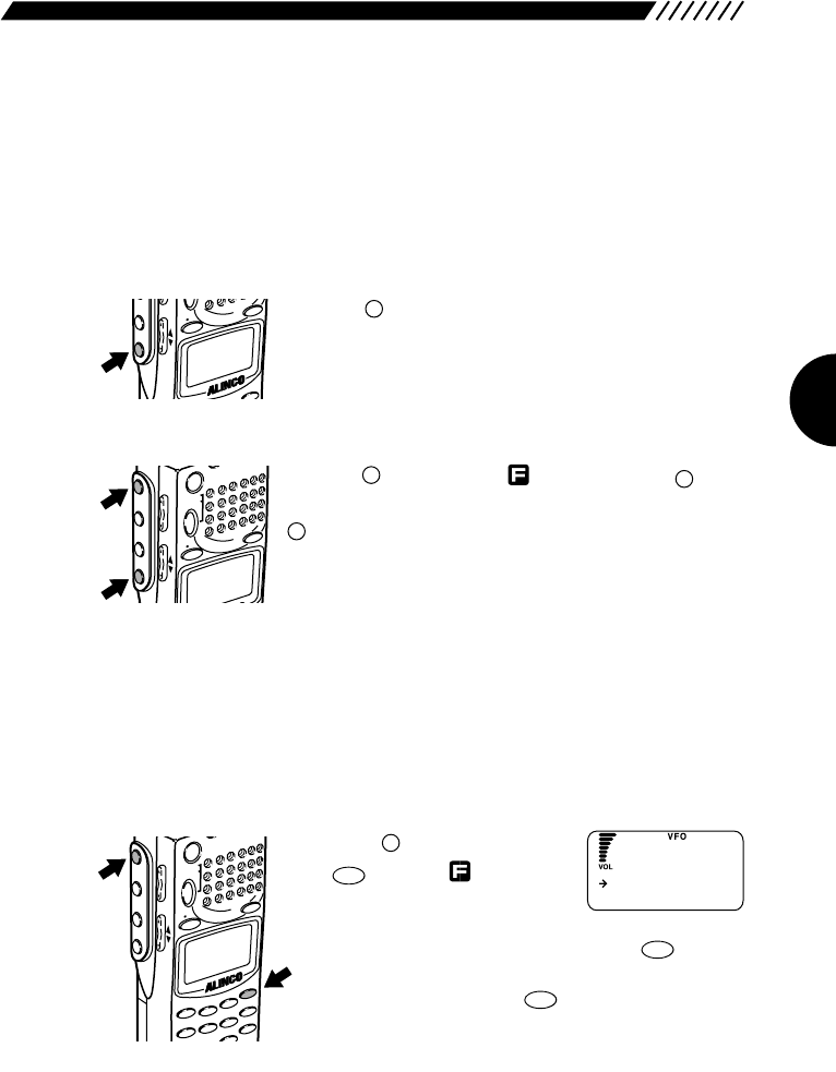
Press the key. The
frequencies on the top and bottom
lines will switch places, with the
letters changing between capital
and lower case.
2.6 Copying frequencies from one band to
the other
The frequency on the currently used band can be copied into the other band as
follows.
Press the key to display ,
followed by the key.
This will copy the frequency on the
currently used band (displayed on
top line next to capital letter) into the other band
(displayed on bottom line next to small case letter).
2.7 Scanning
Scanning is used to locate frequencies with signals present. Basic scanning
operations are as follows.
• To scan Press the key. Scanning will
start and will proceed in the set
frequency steps.
While scanning, an arrow icon is
displayed next to the frequency on currently used band
(displayed on top line next to capital letter). The arrow
points to the left while scanning towards the higher
frequencies.
Note: If CTCSS or A/B Squelch is selected, the scan may be delayed since it takes
some time for judgment.
SCN
A~B S
MODE
AUTO MW
INTELLIGENT
CEIVER
DJ-X2
MIC
SCRTPRIO
REC
CTCSS
F TUNE
A-B S
M NAME
TF
SKIP
STEPATTSET
KL
3
6
9
8
0
5
2
1
4
CLR
ENT
MIC
SCN
RF C
HELP
7
P
DOWN
A=B
VFO
F
POWER
PMS
VFOMR MW
A B
SET
MONI
F
SRCH
LAMP
SQL VOL
WN UP
A=B
VFO
PMS
VFOMR MW
A B
SET
MONI
F
SRCH
LAMP
SQL VOL
DOWN UP
N
B8.
a 145.34
FM
N
A 145.34
b 145.34
FM
N
A 145.34
b 145.34
FM
23
If live frequencies are received, scanning is temporarily stopped. To resume
scanning, turn the dial or press the UP/DOWN key. Scanning can be
automatically resumed by specifying scan resuming conditions. For further
details, see “3.1.15 Specifying scan resuming conditions” (page 43).
• To switch scanning direction
While scanning, press the DOWN key. The arrow icon will face right and
scanning will proceed toward the lower frequencies. To scan toward the higher
frequencies, press the UP key. The scanning direction can also be changed by
turning the dial.
• To cancel scanning
Press the key again.
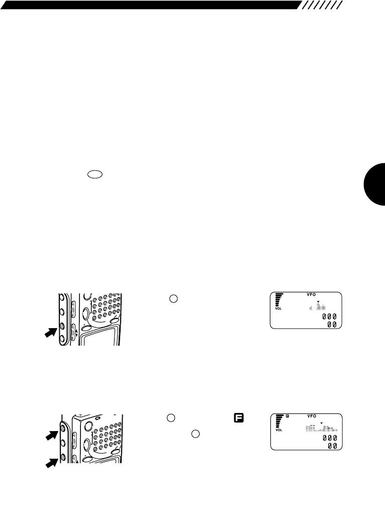
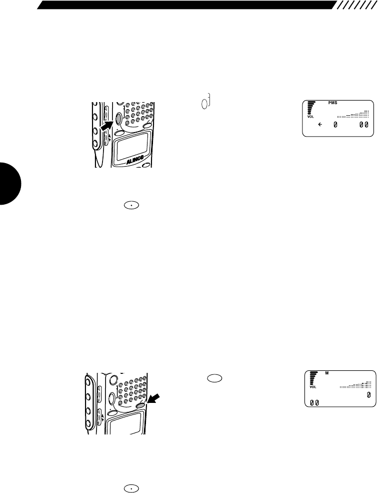
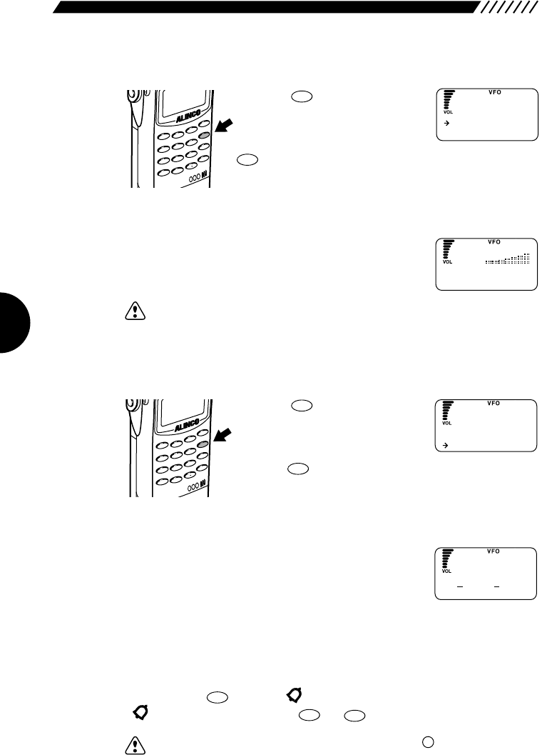
2.8 Searching (Channel Scope)
The search function, or Channel Scope of the DJ-X2000 checks frequencies in
the set frequency steps, and displays signals within a 40-channel or 7-channel
range at one time. The function is useful for checking the spectrum occupancy
at a glance. It is used as follows.
• 40-channel search Press the key on the left side
panel. The DJ-X2000 will start
searching for signals within a 40-
channel range of the currently
received frequency. The search proceeds in the set
frequency steps with the displayed frequency in the center
under ▼mark. The higher channel spectra are displayed
towards the right, and the lower to the left. Vertical length
of each spectrum indicates strength of the signals.
• 7-channel search Press the key to display
Then, press the key on the left
side panel. The DJ-X2000 will start
searching for signals within a 7-
channel range of the currently received frequency. The
search proceeds in the set frequency steps with the
displayed frequency in the center under ▼mark. The
higher channel spectra are displayed towards the right,
and the lower to the left. Vertical length of each spectrum
indicates strength of the signals.
SRCH
F
POWERRX/ST
PMS
VFOMR MW
A B
SET
MONI
F
SRCH
LAMP
SQL VOL
UP
SRCH
PMS
VFOMR MW
A B
SET
MONI
F
SRCH
LAMP
SQL VOL
DOWN UP
SCN
A~B S
W
A81.5
b 145.34
F
M
W
A81.5
b 145.34
F
M
24
• To tune in live frequencies
To move live frequencies to the left,
turn the dial clockwise or press the
UP key. To move them to the right,
turn the dial counterclockwise or
press the DOWN key.
• To cancel the search
Press the key again. This will cancel the search.
Note: • For specifying search steps and search resuming conditions, see “3.1.22
Specifying search resuming conditions” (page 49).
• The search resume condition factory-setting is INTERVAL. Sound is muted
during the search. The search operation is performed every 10 seconds.
• It may be difficult to read a value from the S meter during scanning in the
Channel Scope mode, because the speed is fast.
• The graph displayed in the Channel Scope mode is only in the range of the
currently received radio type. For example, if search is performed around
76.5 MHz of WFM, no channel for less than 76.0 MHz, which is of NFM, is
not displayed.
• If the Channel Scope mode is selected, the battery saving function is
disabled.
• If the search function is turned ON in the MR mode, it may take some time
for the full display of search.
• If scanning is started with the search function turned ON, it may take some
time to start scanning.
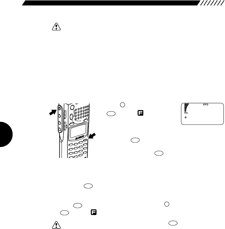
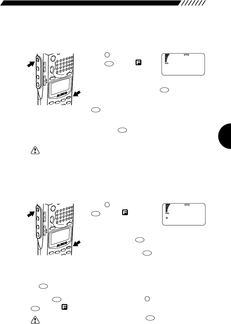
2.9 Monitoring (Squelch OFF)
The monitor function is used to pick up weak signals .
• To turn the monitor ON
Hold down the key. The duration the key is depressed,
the squelch is turned OFF and weak signals can be picked
up . (Noise is heard if no signal is being received.)
When the key is released, the squelch comes back
ON and the DJ-X10 returns to its original state.
• To keep the monitor ON at all times
Press the key to display , followed by the key.
The squelch will remain OFF even after the key has
been released. Pressing the key a
second time will reactivate the squelch.
MONI
MONI
MONI
F
POWERRX/ST
PMS
VFOMR MW
A B
SET
MONI
F
SRCH
LAMP
SQL VOL
N UP
MONI
MONI
POWERRX/ST
PMS
VFOMR MW
A B
SET
MONI
F
SRCH
LAMP
SQL VOL
N UP
SRCH
SET
POWERRX/ST
PMS
VFO MR MW
A B
SET
MONI
F
SRCH
LAMP
SQL VOL
DOWN UP
CLN
S P
W
A81.5
b 145.34
F
M
25
2.10 Turning backlight ON/OFF
The DJ-X2000 has a backlight to make it easier to use at night. The backlight can
be turned ON/OFF as follows.
2.10.1 Turning backlight ON/OFF
manually
• To turn the backlight ON
Press the key. The display will be lit while operating
the dial or keys. Keys also light up when pressed or held
down. The backlight goes OFF automatically if the controls
are not used for approximately 5 seconds.
• To leave the backlight ON at all times
Press the key to display , followed by the key.
The backlight will remain ON until you press the
key again.
2.10.2 Turning backlight ON/OFF based
on the setting
The backlight can be automatically turned ON/OFF in accordance with the
setting. To do so, perform the following steps:
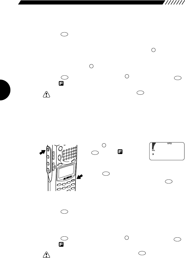
1Display the LAMP screen.
Press the key, and then press
the key with displayed.
The menu will appear. Using the
dial or the UP/DOWN key, point
the arrow at +CONFIG, and then press the key.
The CONFIG menu will appear. Point the arrow at
+LAMP, and then press the key.
ENT
TF
ENT
TF
HELP
SET
F
MODE
AUTO MW
MIC
SCRTPRIO
CTCSSA-B S
M NAME
TF
STEPATTSET
POWER
PMS
VFOMR MW
A B
SET
KL
3
6
9
5
2
1
4
SCN
RF C
HELP
MONI
F
SRCH
LAMP
SQL VOL
DOWN UP
LAMP
LAMP
F
POWER
PMS
VFOMR MW
A B
SET
MONI
F
SRCH
LAMP
SQL VOL
DOWN UP
LAMP
ATTSET
VFOMR MW
A B
HELP
SRCH
LAMP
S
DOWN UP
MOMENTARY
ALTERNATE
LA
M
P
26
2Select a backlight mode as follows:
Using the dial or UP/DOWN key, point the arrow at a desired mode, and then
press the key (the initial setting is the MOMENTARY mode).
AUTO: The backlight is lit for 5 seconds after the dial or key is
used.
MOMENTARY: The backlight remains lit only while the key is being
held down.
ALTERNATE: The backlight is turned alternately ON and OFF every time
the key is pressed.
The display will go back to the CONFIG menu. Point the arrow at END, and then
press the key (or alternatively, press the key, and then press the
key with shown on the display.
Note: If you exit the CONFIG menu by pressing the key, the changed
setting is canceled.
2.11 Turning beep ON/OFF
The beep sound that is emitted when a key is pressed or a specific operation is
performed can be turned ON/OFF and its volume can be controlled as follows:
1Display the BEEP screen.
Press the key, and then press
the key with shown on
the display. The menu will
appear. Using the dial or the
UP/DOWN key, point the arrow at +CONFIG, and then
press the key. The CONFIG menu will appear.
Point the arrow at +BEEP, and then press the key.
2Select a beep sound mode.
Using the dial or the UP/DOWN key, point the arrow at a desired mode, and then
press the key (the initial setting is the HIGH mode).
OFF: The beep sound is turned OFF.
HIGH: The beep sound is emitted at a high level.
LOW: The beep sound is emitted at a low level.
The display will go back to the CONFIG menu. Point the arrow at END, and then
press the key (or alternatively, press the key, and then press the
key with shown on the display).
Note: •If you exit the CONFIG menu by pressing the key, the changed
setting is canceled.
• If stereo earphones are used, the beep sound can be heard from the left
earphone only.
CLR
SKIP
ENT
TF
F
ENT
TF
ENT
TF
ENT
TF
ENT
TF
HELP
SET
F
MODE
AUTO MW
MIC
SCRTPRIOCTCSSA-B S
M NAME
TF
STEPATTSET
POWER
PMS
VFOMR MW
A B
SET
KL
3
6
9
5
2
1
4
SCN
RF C
HELP
MONI
F
SRCH
LAMP
SQL VOL
DOWN UP
CLR
SKIP
ENT
TF
F
ENT
TF
LAMP
LAMP
ENT
TF
High
LO
W
BEEP
27
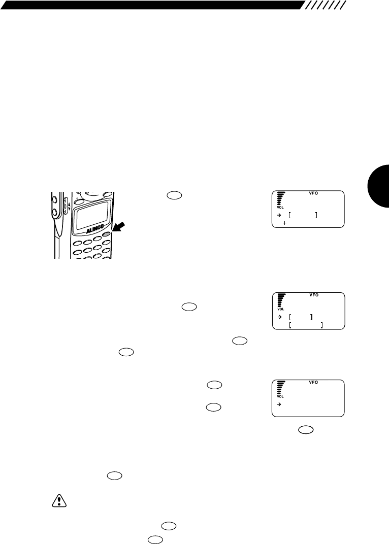
2.12 Locking/Unlocking
This feature locks all but certain keys, preventing accidental operation of the
keys. Keys can be locked/unlocked as follows.
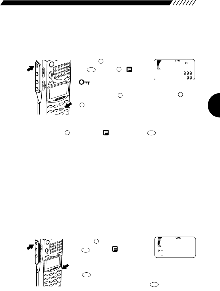
• To lock keys Press the key, and then press
the key with { }
appearing on the display.
will appear on the display
and the keys will be locked except for the POWER
switch, dial, and , VOL/SQL, UP/DOWN, , and
keys.
• To unlock keys
Again, press the key to display , followed by the key. This will
unlock the keys.
2.13 Setting the clock
This section describes the ON and OFF timers that allows you to automatically
turn the power ON/OFF.
The ON timer allows you to set the time that will be taken until the power is
automatically turned ON. The OFF timer allows you to set the time that will be
taken until the power is automatically turned OFF.
Since the timers for the DJ-X2000 is of the 24-hour system, the power is
automatically turned ON/OFF in accordance with the time settings every day.
2.13.1 Setting the OFF timer
1Call up the TIMER menu.
Press the key, and then press
the key with appearing
on the display. The TIMER menu will
appear. Point the arrow at
+CONFIG using the dial or UP/DOWN key, and then press
the key. The CONFIG menu will appear. Point the
arrow at +TIMER and then press the key.
ENT
TF
ENT
TF
HELP
SET
F
MODE
AUTO MW
MIC
SCRT PRIO
REC
CTCSS
F TUNE
A-B S
M NAME
TF
SKIP
STEPATT
SET
POWER
PMS
VFOMR MW
A B
SET
KL
3
6
9
8
0
5
2
1
4
CLR
ENT
SCN
RF C
HELP
7
MONI
F
SRCH
LAMP
SQL VOL
DOWN UP
6
KL
F
LAMP
F
MONI
F
6
KL
F
MODE
AUTO MW
MIC
SCRTPRIOCTCSSA-B S
M NAME
TF
STEPATTSET
POWER
PMS
VFOMR MW
A B
SET
KL
3
6
9
5
2
1
4
SCN
RF C
HELP
MONI
F
SRCH
LAMP
SQL VOL
DOWN UP
N
A81.5
b145.34
FM
O
NTimer
O
FF T ime r
TIMER
28
2Call up the OFF timer screen.
Point the arrow at +OFF Timer using the dial or UP/DOWN
key, and then press the key.
3Set the OFF timer.
Point the arrow at ON using the UP/DOWN key, and then set the time that will be
taken until the power is automatically turned OFF (the initial setting is OFF).
The time can be set up to 24 hours in 30-minute steps.
If OFF is selected, the OFF timer is disabled.
After finishing the setting, press the key. The display will return to the
TIMER menu. Point the arrow at END and then press the key.
(Alternatively, you may press the key,
and then press the key with appearing on the display.)
Note: • If you exit the TIMER menu by pressing the key, the setting is
canceled.
• If you set the OFF timer again, the power is turned OFF after the set time
has elapsed from the time when the key is pressed.
• If the battery is removed or if the hardware reset key is pressed, the setting
is canceled.
2.13.2 Setting the ON timer
1Call up the TIMER menu.
Press the key, and then press
the key with appearing on
the display. The TIMER menu will
appear. Point the arrow at
+CONFIG using the dial or UP/DOWN key, and then press
the key. The CONFIG menu will appear. Point the
arrow at +TIMER, and then press the key.
2Call up the ON Timer screen.
Point the arrow at +ON Timer using the dial or UP/DOWN
key, and then press the key.
3Set the ON timer.
Point the arrow at ON using the UP/DOWN key, and then use the dial to set the
time that will be taken until the power is automatically turned ON (the initial
setting is OFF).
The time may be set up to 24 hours in 30-minute steps.
If OFF is selected, the ON timer is disabled.
ENT
TF
ENT
TF
ENT
TF
HELP
SET
F
MODE
AUTO MW
MIC
SCRT PRIO
REC
CTCSS
F TUNE
A-B S
M NAME
TF
SKIP
STEPATT
SET
POWER
PMS
VFOMR MW
A B
SET
KL
3
6
9
8
0
5
2
1
4
CLR
ENT
SCN
RF C
HELP
7
MONI
F
SRCH
LAMP
SQL VOL
DOWN UP
ENT
TF
CLR
SKIP
ENT
TF
F
ENT
TF
ENT
TF
ENT
TF
:
O
FF
O
N3
FF
O
Timer
O
NTimer
O
FF T ime r
TIMER
O
FF
O
N3
:
N
O
Timer
29
After finishing the setting, press the key. The display will return to the
TIMER menu. Point the arrow at END and then press the key.
(Alternatively, you may press the key, and then press the key with
appearing on the display.)
Note: • If you exit the TIMER menu by pressing the key, the setting is
canceled.
• If you set the ON timer again, the power is turned ON after the set time has
elapsed from the time when the key is pressed.
• If the battery is removed or if the hardware reset key is pressed, the setting
is canceled.
2.14 Basic modes
The DJ-X2000 has three basic modes: VFO, PMS, and MR. The current mode is
displayed along the top of the display.
• VFO mode
This mode is used to select a frequency with the dial or UP/DOWN key and then
receive signals at that frequency. The VFO mode was selected at factory.
• PMS (programmed scan-range) mode
This mode is for tuning in selected channels within a set scan range.
• MR (memory) mode
This mode is for saving often used frequencies in memory. The frequencies can
then be retrieved and tuned in.
2.14.1 VFO mode
The VFO mode has two bands: A and B.
• To enter the VFO mode
Press the key. This will engage
the VFO mode. (If the VFO mode is
already engaged, pressing the
key will switch between bands A and
B.)
To tune in frequencies or switch bands, see "2.4 Setting
frequency" on page 21 and "2.5 Switching frequency band"
on page 23.
A=B
VFO
A=B
VFO
MODE
M NAME
STEPATTSET
PMS
VFOMR MW
A B
SET
3
HELP
MONI
F
SRCH
LAMP
SQL VOL
DOWN UP
HELP
SET
CLR
SKIP
HELP
SET
F
HELP
SET
HELP
SET
N
A 145.34
b8.
FM
30
2.15.2 PMS mode
The PMS mode has a total of 20 programmable bands, 10 each for the capital P
and lower case p.
1Enter the PMS mode.
Press the key. This will engage
the PMS mode. Then, select a
registered band and start scanning.
Bands are preregistered before the
DJ-X2000 is shipped from the factory, but they can be
changed in the expert's mode. (See "3.3.1 Programmed
scan operations" on page 67.)
2Select between P and p.
Press the key to switch back and forth between the capital P and the lower
case p.
3Select a memory bank group.
Press the numeric key for the bank you want. The corresponding programmed
scanning will start. The scanning direction can be changed using the dial or
UP/DOWN key. If you press another numeric key, the corresponding
programmed scanning will start.
2.14.3 MR mode
The memory mode provides five bank groups from A through E. Each bank
group has 10 banks (0-9), each of which allows you to assign a maximum of 40
channels of frequencies (00-39).
1Enter the MR mode.
Press the key. This will
engage the MR mode and will
display registered frequencies and
names.
Frequencies are preregistered before the DJ-X10 is
shipped from the factory, but they can be changed in the
expert's mode. (See "3.5.1 Memorizing frequencies" on
page 46.)
2Select the memory bank group.
Press the key to switch between memory bank groups A, B and C.
3Select a bank.
Press the numeric keys for the bank No. you want in the selected group.
F TUNE
MRMW
POWER
PMS
VFOMR MW
A B
SET
MONI
F
SRCH
LAMP
SQL VOL
DOWN UP
F TUNE
PMS
SET
E
ME
STEPATTSET
PMS
VFOMR MW
A B
SET
HELP
MONI
F
SRCH
LAMP
SQL VOL
DOWN UP
W
P5 1 4 . 75
TV 1 -3ch
FM
A3 1.278
RKB
AM
31
4Select a channel.
Using the dial or UP/DOWN key, select a channel between 00 and 39. The
assigned frequency will appear on the upper line of the display and its name on
the lower line.
2.15 Using HELP menu
The HELP menu is used to display the information on whatever function or
operation you want to know. You can go to different setup screens from the
HELP items and then set the parameters.
1Display the HELP menu.
Press the key. The HELP
menu will appear.
2Select the function on which you want to view an explanation.
Point the arrow at the desired item using the dial or
UP/DOWN key, and then press the key. The
submenu for that item will appear.
Some items have a submenu below them. Similarly point
the arrow at the desired item, and then press the
key. Pressing the key puts you back to the upper layer.
3Select a HELP item.
Point the arrow at Inst. and then press the key. The
selected function will be explained.
Point the arrow at Set! and then press the key. You
will go to the setup screen for that function.
If you point the arrow at any item followed by “!’ and then press the key,
the selected function will be executed.
4Exit the HELP mode.
Hold down the key until you go back to the previous screen.
Note: • The HELP information can be displayed in English. For further details, see
“3.1.7 Selecting displayed language” (page 38).
• Selecting the Set! item exits the HELP mode. To view the HELP information
again, press the key after establishing Set! or canceling it by
pressing the key.
ENT
TF
CLR
SKIP
ENT
TF
ENT
TF
ENT
TF
ENT
TF
HELP
SET
MODE
AUTO MW
MIC
SCRTPRIOCTCSS
NE
A-B S
M NAME
TF
STEPATTSET
VFOMR MW
A B
KL
3
6
9
5
2
1
4
T
SCN
RF C
HELP
SRCH
LAMP
DOWN UP
CLR
SKIP
HELP
KEY
HELP
SET
P
OW
ER
KEY
セツメイ
セッテイ
!
T
O
NE
ENT
TF
CLR
SKIP
ENT
TF
32
3. Other Useful Functions
This chapter describes the useful functions of the DJ-X2000.
3.1 Functions common to all modes
This section describes the functions that are commonly available in the VFO,
PMS, and MR modes.
3.1.1 Selecting a signal mode
Press the key, and then press
the key with appearing on
the display. The MODE screen will
appear. Point the arrow at the
desired signal mode using the dial or UP/DOWN key, and
then press the key.
A signal mode can be selected from AM, NFM, WFM, USB,
LSB, CW, and AUTO. If AUTO is selected, the most
suitable signal mode will be automatically selected in
accordance with the received frequency (the initial mode
is AUTO).
Note: In the PMS or MR mode, when DIRECT WR is turned ON (the initial setting is
OFF), a signal mode can be selected. For further details, see “3.3.31 Directly
changing the setting” (page 63).
3.1.2 Setting the frequency step
Frequency step is the distance that the DJ-X2000 moves
from one frequency to the next. It can be selected from 23
fixed settings.
Press the key to display , followed by the key.
This will display the MODE menu. Then, move
the arrow to the signal mode you want, using the dial or
the UP/DOWN key, and press the key.
A frequency step can be selected from AUTO STEP,
50 Hz, 100 Hz, 200 Hz, 500 Hz, 1 kHz, 2 kHz, 5 kHz,
6.25 kHz, 8.33 kHz, 9 kHz, 10 kHz, 12.5 kHz, 15 kHz,
20 kHz, 25 kHz, 30 kHz, 50 kHz, 100 kHz, 125 kHz,
150 kHz, 200 kHz, 250 kHz, 500 kHz, and USER STEP.
ENT
TF
2
STEP
F
MODE
AUTO MW
MIC
SCRTPRIO
REC
CTCSS
F TUNE
A-B S
M NAME
TF
SKIP
STEPATTSET
POWER
PMS
VFOMR MW
A B
SET
KL
3
6
9
8
0
5
2
1
4
R
ENT
SCN
RF C
HELP
7
MONI
F
SRCH
LAMP
SQL VOL
DOWN UP
ENT
TF
1
MODE
F
MODE
AUTO MW
MIC
SCRTPRIO
REC
CTCSS
F TUNE
A-B S
M NAME
TF
SKIP
STEPATTSET
POWER
PMS
VFOMR MW
A B
SET
KL
3
6
9
8
0
5
2
1
4
R
ENT
SCN
RF C
HELP
7
MONI
F
SRCH
LAMP
SQL VOL
DOWN UP
AUT
O
AM
M
O
DE
W
FM
AUT
O
STEP
5Hz
STEP 1 KHz
33
Note: In the PMS or MR mode, setting DIRECT WR to ON enables selection of a
frequency step and radio type and adjustment of the attenuator and CTCSS
decoders. For further details, see “3.3.31 Directly changing the setting”
(page 63).
If AUTO STEP is selected, the most suitable frequency step for the received
frequency band will be automatically selected.
If USER STEP (optional) is selected, a frequency step can be selected freely in a
range between 50 Hz and 499.95 kHz.
Example: To enter 150 kHz, press: , , , ,
To enter 450 kHz, press: , , , ,
Even if a frequency that cannot be divided by the selected
step is entered, it is accepted. In this case, however, the
beep sound is emitted and “S” appears on the display
showing that the DJ-X2000 is operating in non-standard
steps.
Note: The frequency step in the AM mode is fixed to 10 kHz for the North American
version and 9 kHz for the European version.
3.1.3 Attenuating interference from
other channels (ATT)
The attenuator lessens interference from strong signals on other channels so that
signal you want is heard clearly.
1Call up the ATT screen.
Press the key, and then press
the key with appearing on
the display. The ATT screen will
appear.
2Selecting an attenuation level
Point the arrow at the desired attenuation level using the dial or UP/DOWN key
(the initial setting is OFF).
OFF Turns the attenuator OFF.
LOW Attenuates the affected signals by approx. 10 dB.
HIGH Attenuates the affected signals by approx. 20 dB.
ATT will appear on the display showing that the attenuation function is turned
ON.
3
ATT
F
MODE
AUTO MW
MIC
A-B S
M NAME
STEPATTSET
POWER
PMS
VFOMR MW
A B
SET
KL
3
6
2
1
RF C
HELP
MONI
F
SRCH
LAMP
SQL VOL
DOWN UP
ENT
TF
5
AUTO MW
4
MIC
F TUNE
0
REC
ENT
TF
5
AUTO MW
1
MODE
F TUNE
0
REC
N
A81.
b 145.34
FM
O
FF
L
OW
ATT
34
Note: • The attenuation level slightly varies depending on the frequency.
• In the PMS or MR mode, setting DIRECT WR to ON enables selection of a
frequency step and radio type and adjustment of the attenuator and CTCSS
decoders. For further details, see “3.3.31 Directly changing the setting”
(page 63).
3.1.4 Battery Save
When ON, the battery-save feature automatically saves on battery power
whenever keys are not used or a signal is not picked up for a certain amount of
time.
1Call up the BATT SAVE screen.
Press the key, and then press
the key with appearing on
the display.
The menu will appear. Point the
arrow at +CONFIG using the dial or UP/DOWN key, and
then press the key.
The CONFIG menu will appear. Point the arrow at +BATT
SAVE and then press the key.
2Select an ON/OFF ratio for the battery saving feature.
Point the arrow at the desired ON/OFF ratio using the dial or UP/DOWN key, and
then press the key (the initial setting is NORMAL).
The display will return to the CONFIG menu. Point the arrow at END and then
press the key (Alternatively, you may press the key, and then press
the key with appearing on the display).
Note: • If you exit the CONFIG menu by pressing the key, the changed
setting will be canceled.
• If LONG is selected, the time to keep the internal power source OFF
becomes longer. This extends the battery life, but delays the receiving
reaction.
CLR
SKIP
F
ENT
TF
ENT
TF
ENT
TF
ENT
TF
HELP
SET
F
MODE
AUTO MW
MIC
SCRTPRIO
REC
CTCSS
F TUNE
A-B S
M NAME
TF
SKIP
STEPATTSET
POWER
PMS
VFOMR MW
A B
SET
KL
3
6
9
8
0
5
2
1
4
CLR
ENT
SCN
RF C
HELP
7
MONI
F
SRCH
LAMP
SQL VOL
DOWN UP
O
FF
SHORT
BATT SAVE
ENT
TF
35
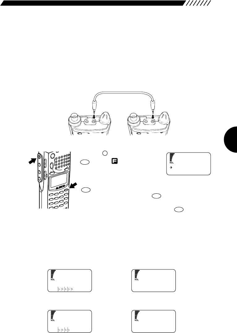
3.1.5 Copying data between two
receivers (CLONE)
You can copy settings stored in memory from one DJ-X2000 (master) to another
(slave). This is referred to as "cloning". Cloning requires a cable with 2.5ø stereo
plug to connect the two receivers.
1Turn ON two DJ-X2000 units and interconnect them.
Detach the cap from the top of each unit. As illustrated below, connect the cable
between the CLN terminals.
2Execute a cloning command.
Press the key, and then press the
key with appearing on the
display. The CLONE menu will
appear. Point the arrow at +CONFIG
using the dial or UP/DOWN key, and then press the
key. The CONFIG menu will appear. Point the arrow
at +CLONE, and then press the key.
Point the arrow at the desired cloning command using the
dial or UP/DOWN key, and then press the key. This
operation is not required for the slave unit.
READ Copies the data stored in the memory from the other DJ-X2000 unit.
WRITE Copies the data stored in the memory to the other DJ-X2000 unit.
END Cancels the cloning command without copying any data.
• When READ is selected:
Displayed on the master unit Displayed on the slave unit
• When WRITE is selected:
Displayed on the master unit Displayed on the slave unit
W
ORK I NG
CL
O
NE
S
END I NG
CL
O
NE DATA
W
ORK I NG
CL
O
NE
R
ECEIVING
CL
O
NE DATA
ENT
TF
ENT
TF
HELP
SET
F
MODE
AUTO MW
MIC
SCRTPRIO
REC
CTCSS
F TUNE
A-B S
M NAME
TF
SKIP
STEPATTSET
POWER
PMS
VFOMR MW
A B
SET
KL
3
6
9
8
0
5
2
1
4
CLR
ENT
SCN
RF C
HELP
7
MONI
F
SRCH
LAMP
SQL VOL
DOWN UP
ENT
TF
Audio plug with
2.5 mm dia. pin
W
RITE
READ
CL
O
NE
36
When the cloning procedure is finished, the slave unit returns to the normal
screen and the master unit to the CLONE menu.
3Finish the cloning procedure.
Once the cloning procedure is finished, disconnect the cable from both DJ-
X2000 units. Press the key on the master unit to exit the CLONE menu.
The slave unit can be used without this operation.
3.1.6 Selecting a communication speed
A communication speed during the cloning procedure or communication with a
personal computer can be selected (the initial setting is 38400 bps).
• To select 38400 bps:
Turn the power ON while holding down the key.
• To select 19200 bps:
Turn the power ON while holding down the key.
• To select 9600 bps:
2
STEP
MODE
AUTO MW
MIC
A-B S
M NAME
STEPATTSET
POWER
PMS
VFO MR MW
A B
SET
KL
3
6
2
1
RF C
HELP
MONI
F
SRCH
LAMP
SQL VOL
DOWN UP
3
ATT
MODE
AUTO MW
MIC
A-B S
M NAME
STEPATTSET
POWER
PMS
VFO MR MW
A B
SET
KL
3
6
2
1
RF C
HELP
MONI
F
SRCH
LAMP
SQL VOL
DOWN UP
CLR
SKIP
CAUTION: • Do not disconnect the cable, nor turn the power OFF during the
cloning procedure.
• If a cloning error occurs, press the hardware reset key or remove
the battery.
37
Note: • The cloning procedure or communication with a personal computer is not
possible between DJ-X2000 units with different communication speeds.
• The initial value is a high speed of 38400 bps. If there are too many
communication errors at this speed, retry the communication at a lower
speed, e.g., 9600 bps.
3.1.7 Selecting a language mode
The DJ-X2000 was set to the English mode at factory, but may be changed to
the English mode.
1Call up the LANGUAGE screen.
Press the key, and then
key with shown on the display.
The LANGUAGE screen will
appear. Point the arrow at
+CONFIG using the dial or
UP/DOWN key, and then press the key.
The CONFIG menu will appear. Point the arrow at
+LANGUAGE and then press the key.
2Select a language mode.
Point the arrow at English or Japanese using the dial or UP/DOWN key, and
then press the key (the initial setting is English).
The display will return to the CONFIG menu. Point the arrow at END and then
press the key (Alternatively, you may press the key, and then press
the key with shown on the display).
Note: If you exit the CONFIG menu by pressing the key, the changed setting
is canceled.
3.1.8 Field-strength meter
The level of the aperiodic field-strength meter can be set. When the electric field
strength reaches the set level, the buzzer sounds. This feature can be used,
e.g., to check for transmission from a bug.
The DJ-X2000 provides the following two modes to show electric field strength:
Meter display mode Shows changes in electric field strength using
the S-meter and beep sound.
Set level mode Starts sounding the buzzer when electric field
strength reaches the set level.
CLR
SKIP
F
ENT
TF
ENT
TF
ENT
TF
ENT
TF
HELP
SET
F
MODE
AUTO M
W
MIC
A-B S
M NAME
STEPATTSET
POWER
PMS
VFO MR MW
A B
SET
KL
3
6
2
1
RF C
HELP
MONI
F
SRCH
LAMP
SQL VOL
DOWN UP
ENT
TF
English
Japanese
LANGUAGE
38
• Meter display mode
1Call up the CHECKER screen.
Press the . The RF CHECK
menu will appear. Point the arrow
at CHECKER using the dial or
UP/DOWN key, and then press the
key.
2Measure the electric field strength.
As the electric field strength increases, the S-meter
shows higher levels with faster beeping.
Note: Since the electric-field meter is intended to measure the nearby strong
electric field strength, it reacts at the sensitivity of approximately -50 dBm
minimum. The sensitivity varies depending on the frequency.
• Set level mode:
1Call up the CALL WAIT screen.
Press the key. The RF
CHECK menu will appear. Point
the arrow at CALL WAIT using the
dial or UP/DOWN key, and then
press the key.
2Set up the set level mode.
Set the level by selecting a number from 1 through 9 (the
initial setting is 3) using the dial, the UP/DOWN key, or a
numeric key.
When the electric field strength exceeds the set level, the buzzer sounds with
{bell icon} blinking on the display. The buzzer sounds for 10 seconds and {bell
icon} continues to blink.
• Canceling the set level mode
If you press the key when is blinking, this blinking stops.
If is not blinking, pressing the or key cancels this mode.
Note: In the set level mode, only the POWER switch and key are valid.
LAMP
RFC
M NAME
CLR
SKIP
ENT
TF
RFC
M NAME
MODE
AUTO MW
INTELLIGENT
CEIVER
DJ-X2
MIC
SCRTPRIO
REC
CTCSS
F TUNE
A-B S
M NAME
TF
SKIP
STEPATTSET
KL
3
6
9
8
0
5
2
1
4
CLR
ENT
MIC
SCN
RF C
HELP
7
P
DOWN
ENT
TF
RFC
M NAME
MODE
AUTO MW
INTELLIGENT
CEIVER
DJ-X2
MIC
SCRTPRIO
REC
CTCSS
F TUNE
A-B S
M NAME
TF
SKIP
STEPATTSET
KL
3
6
9
8
0
5
2
1
4
CLR
ENT
MIC
SCN
RF C
HELP
7
P
DOWN
CLR
SKIP
RF
IN
CHECK
CHECK G
CHECKER
Ca l lWa i t
RF
KCHEC
RF CALL LVL3
CALL WA I T ING
CHECKER
Ca l l Wa i t
RF
CHECK
39
3.1.9 Displaying battery voltage
The battery voltage can be displayed as follows:
1Call up the BATT VOLT screen.
Press the key, and then
press the key with
shown on the display.
The BATT VOLT menu will
appear. Point the arrow at +CONFIG using the dial or
UP/DOWN key, and then press the key. The
CONFIG menu will appear. Point the arrow at +BATT
VOLT using the dial or UP/DOWN key, and then press
the key.
The battery voltage will be shown on the display.
If you press the key, the battery voltage
disappears.
Note: • The measured value is updated every 0.5 second.
• If an external power source (10-16 V) is used, “OVER 8V” is displayed.
3.1.10 Setting the reception tone
The reception tone can be set to either of 2 levels as follows:
1Call up the TONE screen.
Press the key, and then press
the key with shown on
the display.
The TONE menu will appear.
Point the arrow at +CONFIG using the dial or UP/DOWN
key, and then press the key.
The CONFIG menu will appear. Point the arrow at
+TONE and then press the key.
2Set the reception tone.
Point the arrow at High or Low using the dial or UP/DOWN key, and then press
the key (the initial setting is High).
The display will return to the CONFIG menu. Point the arrow at END and then
press the key (Alternatively, you may press the key, and then press the
key with shown on the display).
Note: If you exit the CONFIG menu by pressing the key, the changed setting
is canceled.
CLR
SKIP
ENT
TF
F
ENT
TF
ENT
TF
ENT
TF
ENT
TF
HELP
SET
F
MODE
AUTO MW
MIC
A-B S
M NAME
STEPATTSET
POWER
PMS
VFOMR MW
A B
SET
KL
3
2
1
RF C
HELP
MONI
F
SRCH
LAMP
SQL VOL
DOWN UP
CLR
SKIP
ENT
TF
ENT
TF
HELP
SET
F
MODE
AUTO MW
MIC
A-B S
M NAME
STEPATTSET
POWER
PMS
VFOMR MW
A B
SET
KL
3
2
1
RF C
HELP
MONI
F
SRCH
LAMP
SQL VOL
DOWN UP
B
4.9V
ATT VOLT
High
L
OW
T
O
NE
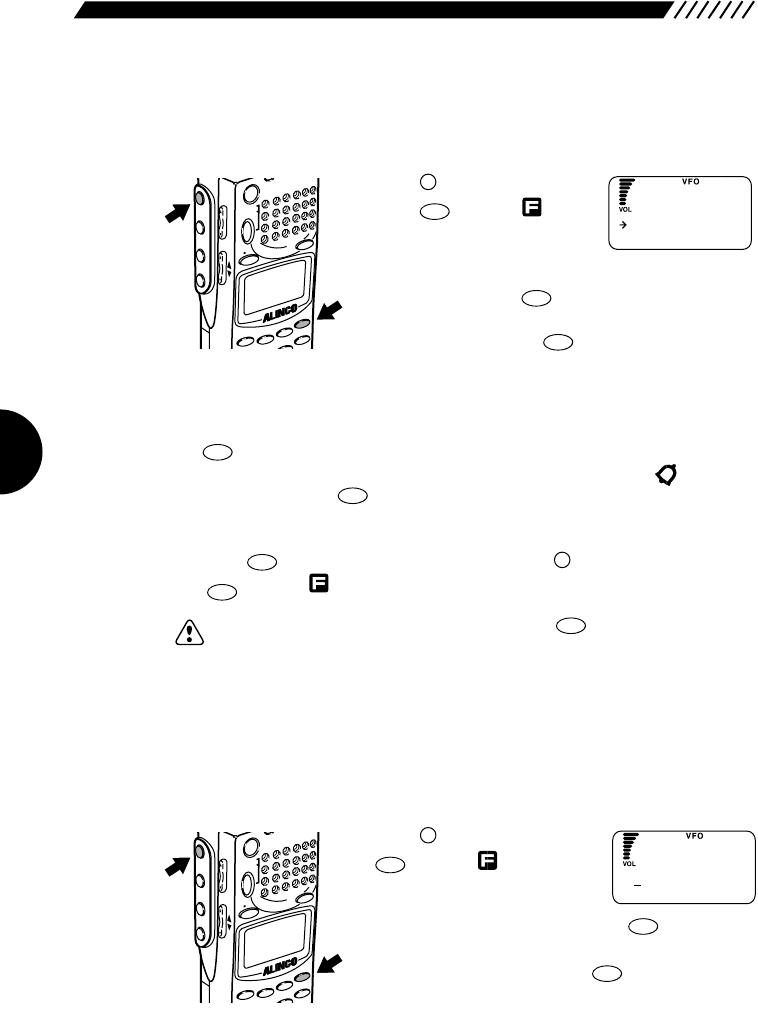
40
3.1.11 Selecting the BELL mode
In this mode, when squelch is canceled, the buzzer sounds.
1Call up the BELL screen.
Press the key, and then
press the key with
shown on the display.
The BELL menu will appear.
Point the arrow at +CONFIG using the dial or UP/DOWN
key, and then press the key.
The CONFIG menu will appear. Point the arrow at
+BELL and then press the key.
2Turn the BELL mode ON/OFF.
Point the arrow at ON or OFF using the dial or UP/DOWN key, and then press
the key (the initial setting is OFF).
When squelch is canceled, the buzzer sounds for 10 seconds and starts
blinking. Pressing the key cancels this blinking.
The display will return to the CONFIG menu. Point the arrow at END and then
press the key (Alternatively, you may press the key, and then press
the key with shown on the display).
Note: If you exit the CONFIG menu by pressing the key, the changed setting
is cancelled.
3.1.12 Changing the initial message
The initial message that appears after the power has been turned ON can be
changed as follows:
1Call up the OPENINGMG screen.
Press the key, and then press
the key with shown on
the display.
The menu will appear. Point the
arrow at +CONFIG and then press the key.
The CONFIG menu will appear. Point the arrow at
+OpeningMG and then press the key.
ENT
TF
HELP
SET
F
MODE
AUTO MW
MIC
A-B S
M NAME
STEPATTSET
POWER
PMS
VFOMR MW
A B
SET
KL
3
2
1
RF C
HELP
MONI
F
SRCH
LAMP
SQL VOL
DOWN UP
CLR
SKIP
ENT
TF
F
ENT
TF
CLR
SKIP
ENT
TF
ENT
TF
ENT
TF
HELP
SET
F
MODE
AUTO MW
MIC
A-B S
M NAME
STEPATTSET
POWER
PMS
VFOMR MW
A B
SET
KL
3
2
1
RF C
HELP
MONI
F
SRCH
LAMP
SQL VOL
DOWN UP
OFF
ON
BELL
1
ABCDEFGH I JK
AL INCO
LINE
M
S
G
ENT
TF
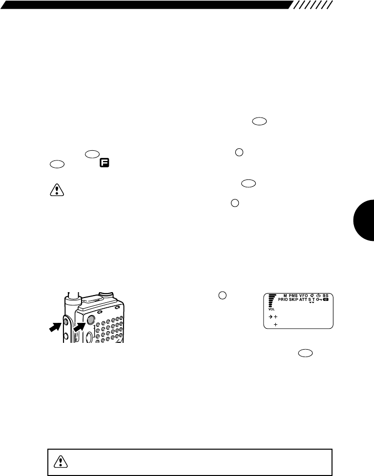
41
2Enter a message.
Select each character by turning the dial, and then establish it by pressing the
DOWN key. Pressing the UP key allows you to cancel the established character.
Up to 36 characters may be entered (the initial setting is ALINCO INTELLIGENT
RECEIVER).
3Finish the setting.
After you have finished entering the characters, press the key.
The display will return to the CONFIG menu. Point the arrow at END and then
press the key (Alternatively, you may press the key, and then press the
key with shown on the display.
Note: • If you exit the CONFIG menu by pressing the key, the changed
setting is canceled.
• If you turn the dial while holding down the key, you can move 11
characters ahead.
3.1.13 Resetting the receiver
This command resets the DJ-X2000. Be careful as all settings you made up till
now may be cleared from memory, depending on your selection.
While holding down the key,
turn ON the power. When the DJ-
X2000 starts up, the USER RESET
menu will appear on the display.
Move the arrow to the reset command you want, using
the dial or the UP/DOWN key. Then, press the key.
Reset commands are described here following.
CANCEL Cancels the reset command entirely.
SYSTEM Initializes user-set functions, but it does not clear memory
channels. (Choose this normally.)
ALL Clears all functions and memories including factory-set
bandplan.
ENT
TF
F
POWERRX/ST
PMS
MR MW
SET
MONI
F
SR
SQL VOL
CLN
S P
F
CLR
SKIP
ENT
TF
F
ENT
TF
ENT
TF
CANCEL
SYSTEM
USER RESET
CAUTION: It takes time to complete the resetting. Do not turn ON the power
during the resetting.
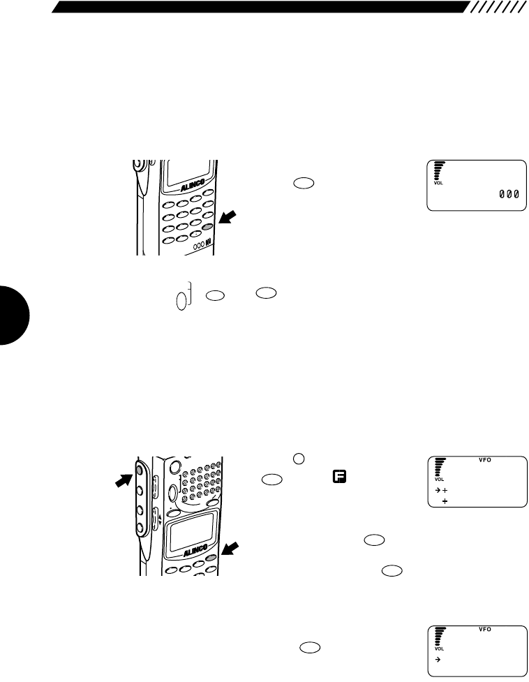
42
3.1.14 Tuning in frequencies in the
PMS/MR modes (M.TUNE)
You can tune in frequencies in the PMS and MR modes. You do not have to
return to the VFO mode.
• To tune in a frequency
While in the PMS or MR mode,
press the key. A frequency
and M.TUNE will appear on the
display. Turn the dial or press the
UP/DOWN keys to tune in a frequency.
• To cancel M.TUNE
Press the , or keys.
3.1.15 Setting scan resume condition
(SCAN MODE)
This setting determines what the DJ-X2000 does when it picks up a signal while
scanning. This is referred to as the “scan mode”.
1Call the SCAN menu.
Press the key, and then press
the key with shown on
the display.
The SCAN menu will appear.
Point the arrow at +CONFIG using the dial or UP/DOWN
key, and then press the key.
The CONFIG menu will appear. Point the arrow at
+SCAN and then press the key.
2Call up the SCAN MODE screen.
Point the arrow at +SCAN MODE using the dial or
UP/DOWN key, and then press the key.
ENT
TF
ENT
TF
ENT
TF
HELP
SET
F
MODE
AUTO MW
MIC
A-B S
M NAME
STEPATTSET
POWER
PMS
VFOMR MW
A B
SET
KL
3
2
1
RF C
HELP
MONI
F
SRCH
LAMP
SQL VOL
DOWN UP
MRMW
A=B
VFO
PMS
SET
ENT
TF
MODE
AUTO MW
INTEL
LIGENT
CEIVER
DJ-X2
MIC
SCRTPRIO
REC
CTCSS
F TUNE
A-B S
M NAME
TF
SKIP
STEPATTSET
KL
3
6
9
8
0
5
2
1
4
CLR
ENT
MIC
SCN
RF C
HELP
7
P
DOW
N
W
82.5
M.TUNE
FM
SCAN M
O
DE
BUSY T i me r
SCAN
BUSY
ST
O
P
SCAN M
O
DE
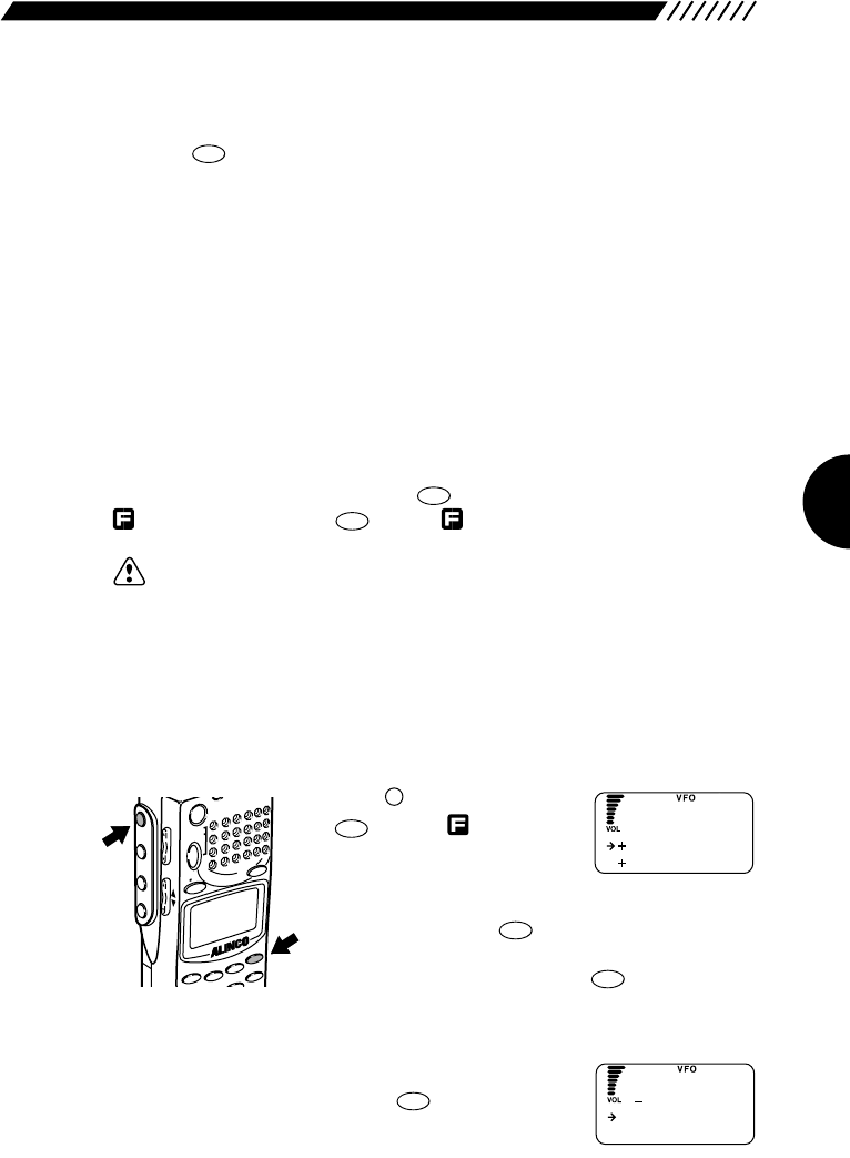
43
3Select a scanning option.
Point the arrow at the desired option using the dial or UP/DOWN key, and then
press the key. The available scanning options are described below (the
initial setting is BUSY):
BUSY Busy scan. The DJ-X2000 stays on any signal it locates until
the signal vanishes. Once the signal dis appeares, scanning
is resumed.
STOP The DJ-X2000 stops scanning on the first signal it locates.
Scanning is not resumed after the signal vanishes.
TIMER When the currently transmitted signals of any frequency are
received, scanning is paused for a given period of time. After
this specific time period, scanning is resumed even if the
signals are being received. For setting the pause period, see
“3.1.17 Setting the scanning pose period” (page 45).
The display will return to the SCAN menu. Point the arrow at END using the dial
or UP/DOWN key, and then press the key (Alternatively, you may press the
key, and then press the key with shown on the display).
Note: If you exit the SCAN menu by pressing the <CLR> menu, the changed
setting is canceled.
3.1.16 Setting scan signal level
This setting specifies the minimum signal level used in scanning. Scanning will
stop only when the DJ-X2000 locates a signal of this strength or stronger.
1Call up the SCAN menu.
Press the key, and then press
the key with shown on
the display.
The SCAN menu will appear.
Point the arrow at +CONFIG using the dial or UP/DOWN
key, and then press the key.
The CONFIG menu will appear. Point the arrow at
+SCAN SETUP and then press the key.
2Call up the S_LEVEL menu.
Move the arrow to +S_LEVEL using the dial or the
UP/DOWN key, and then press the key.
ENT
TF
ENT
TF
ENT
TF
HELP
SET
F
MODE
AUTO MW
MIC
A-B S
M NAME
STEPATTSET
POWER
PMS
VFOMR MW
A B
SET
KL
3
2
1
RF C
HELP
MONI
F
SRCH
LAMP
SQL VOL
DOWN UP
ENT
TF
ENT
TF
ENT
TF
SCAN M
O
DE
BUSY T i me r
SCAN
S
O
FF
O
N1
LEVEL
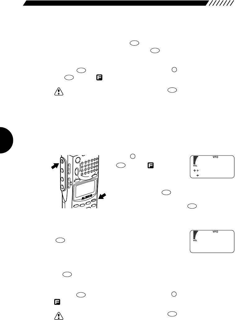
44
3Select an S-meter level.
Point the arrow at ON using the UP/DOWN key. Select a level from 1 through 7
using the dial, and then press the key. If you do not want to select any S-
meter level, select OFF and then press the key (the initial setting is OFF).
Higher levels require stronger signals to stop scanning.
The display will return to the SCAN mode. Point the arrow at END and then
press the key (Alternatively, you may press the key, and then press
the key with shown on the display).
Note: If you exit the SCAN menu by pressing the key, the changed setting is
canceled.
3.1.17 Setting the scanning pause
period
The scanning pause period for the TIMER option can be set.
1Call up the SCAN menu.
Press the key, and then press
the key with shown on
the display.
The SCAN menu will appear.
Point the arrow at +CONFIG using the dial or UP/DOWN
key, and then press the key.
The CONFIG menu will appear. Point the arrow at
+SCAN SETUP and then press the key.
2Call up the BUSY TIMER screen.
Point the arrow at +Busy Timer and then press the
key.
3Set the scanning pause period.
Set the scanning pause period using the dial or UP/DOWN key, and then press
the key (the initial setting is 5s).
The display will return to the SCAN menu. Point the arrow at END and then
press the key (Alternatively, you may press the key, and then press the
shown on the display).
Note: If you exit the SCAN menu by pressing the key, the changed setting is
canceled.
CLR
SKIP
F
ENT
TF
ENT
TF
ENT
TF
ENT
TF
ENT
TF
HELP
SET
F
MODE
AUTO MW
MIC
A-B S
M NAME
STEPATTSET
POWER
PMS
VFOMR MW
A B
SET
KL
3
2
1
RF C
HELP
MONI
F
SRCH
LAMP
SQL VOL
DOWN UP
CLR
SKIP
F
ENT
TF
ENT
TF
ENT
TF
ENT
TF
SCAN M
O
DE
BUSY T i me r
SCAN
B
5s
usyTimer
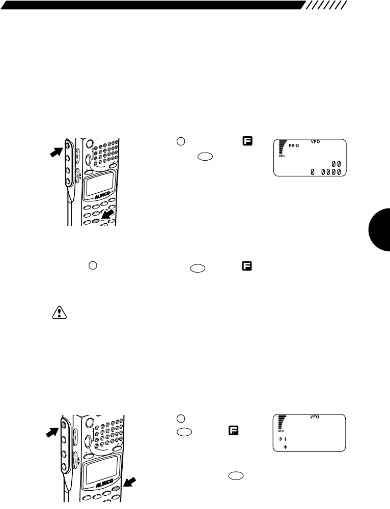
45
3.1.18 Turning the priority function
ON/OFF
The priority function checks another channel (priority channel) every 5 seconds
while monitoring the current frequency. For the settings of the priority feature,
see “3.1.19 Selecting a priority option” (page 46), “3.1.20 Selecting a priority
channel” (page 47), and “3.1.21 Specifying a priority interval” (page 48).
• To turn the priority function ON
Press the key to display ,
followed by the key. PRIO
will appear at the top of the
display. This means the priority
function is ON.
• Turn the priority feature OFF.
Press the key, and then press the key with shown on the display.
“PRI” shown at the top of the screen will disappear showing that the priority
feature is turned OFF.
Note: If the priority feature is ON, the CH SCOPE mode is disabled.
3.1.19 Selecting a priority option
Select an operation option of the DJ-X-2000, which is applicable if signals are
received on the priority channel when the priority feature is active.
1Call up the PRIO menu.
Press the key, and then
press the key with
shown on the display.
The PRIO menu will appear.
Point the arrow at +PRIO using the dial or UP/DOWN
key, and then press the key.
ENT
TF
F
MODE
AUTO MW
MIC
A-B S
M NAME
STEPATTSET
POWER
PMS
VFOMR MW
A B
SET
KL
3
2
1
RF C
HELP
MONI
F
SRCH
LAMP
SQL VOL
DOWN UP
8
PRIO
F
8
PRIO
F
MODE
AUTO MW
MIC
SCRTPRIO
REC
CTCSS
F TUNE
A-B S
M NAME
TF
SKIP
STEPATTSET
PO
WER
PMS
VFOMR MW
A B
SET
KL
3
6
9
8
5
2
1
4
ENT
SCN
RF C
HELP
7
MONI
F
SRCH
LAMP
SQL VOL
DOWN UP
N
A 145.34
b8.
FM
PR I FREQ
PR I M
O
DE
PR I
O
HELP
SET
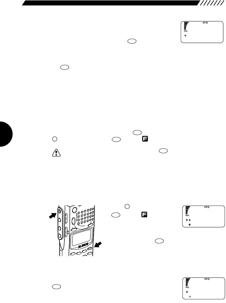
46
2Call up the PRI MODE screen.
Point the arrow at +PRI MODE using the dial or
UP/DOWN key, and then press the key.
3Select a priority option.
Select a priority option using the dial or UP/DOWN key, and then press
the key. The available options are listed below (the initial setting is STOP).
BUSY When signal is received on the priority channel, the DJ-X2000
stays on the priority frequency until ithe signal vanishes.
STOP When signal is received on the priority channel, the DJ-X2000
stays on the priority frequency even after the signal vanishes.
TIMER Once signals are received on the priority channel, they will be
received for a given interval. For specifying this interval, see
“3.1.21 Specifying a priority interval” (page 48).
The display will return to the PRIO menu. Point the arrow at END using the dial
or UP/DOWN key, and then press the key (Alternatively, you may press the
key, and then press the key with shown on the display).
Note: If you exit the PRIO menu by pressing the menu, the changed setting
is canceled.
3.1.20 Setting priority signal channel
This setting allots a memory channel for the priority scan. The priority scan must
be ON for this setting to be effective.
1Call up the PRIO menu.
Press the key, and then press
the key with shown on
the display.
The PRIO menu will appear.
Point the arrow at +PRIO using the dial or UP/DOWN
key, and then press the key.
2Call up the PRIO FREQ screen.
Point the arrow at +PRIO FREQ and then press the
key.
ENT
TF
ENT
TF
HELP
SET
F
MODE
AUTO MW
MIC
A-B S
M NAME
STEPATTSET
POWER
PMS
VFOMR MW
A B
SET
KL
3
2
1
RF C
HELP
MONI
F
SRCH
LAMP
SQL VOL
DOWN UP
CLR
SKIP
F
ENT
TF
ENT
TF
ENT
TF
ENT
TF
PR I FREQ
PR I M
O
DE
PR I
O
Now FREQ
MEM
O
RY
PR I FREQ
ST
O
P
TIMER
PR I
MO
DE
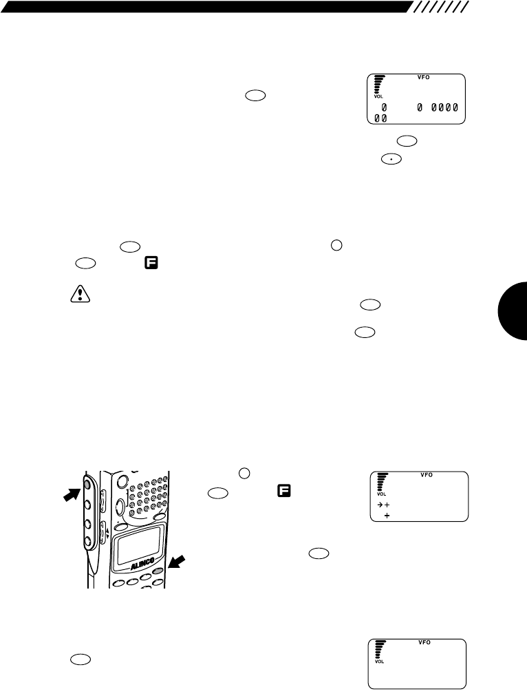
47
3Call up the PRI MEMORY screen.
Point the arrow at +MEMORY using the dial or
UP/DOWN key, and then press the key.
4Select a channel.
Select the desired memory bank and channel, and then press the key.
The memory bank can be selected from A through E using the key. The
bank number can be selected using the dial or a numeric key. Pressing the
UP/DOWN key moves the arrow, allowing you to select the channel number with
the dial or a numeric key.
The display will return to the PRI FREQ screen. Point the arrow at END and then
press the key (Alternatively, you may press the key, and then press the
key with shown on the display).
Note: • To select the currently received frequency for the priority channel, point the
arrow at NOW FREQ in step 2 and then press the key (the initial
setting is NOW FREQ).
If you point the arrow at NOW PRI and press the key, the frequency
currently selected for the priority channel is displayed.
• If you exit the PRI FREQ screen, the changed setting is canceled.
3.1.21 Specifying a priority interval
Specify an interval for activate the priority feature.
1Call up the PRIO menu.
Press the key, and then press
the key with shown on
the display.
The PRIO menu will appear.
Point the arrow at +PRIO using the dial or UP/DOWN
key, and then press the key.
2Call up the PRI TIMER screen.
Point the arrow at +PRI TIMER and then press the
key.
ENT
TF
ENT
TF
HELP
SET
F
MODE
AUTO MW
MIC
A-B S
M NAME
STEPATTSET
POWER
PMS
VFOMR MW
A B
SET
KL
3
2
1
RF C
HELP
MONI
F
SRCH
LAMP
SQL VOL
DOWN UP
ENT
TF
ENT
TF
F
ENT
TF
ENT
TF
ENT
TF
PR I FREQ
PR I M
O
DE
PR I
O
P
5s
RI Timer
P
A8.
RI
M
E
MO
RY
ENT
TF
F TUNE
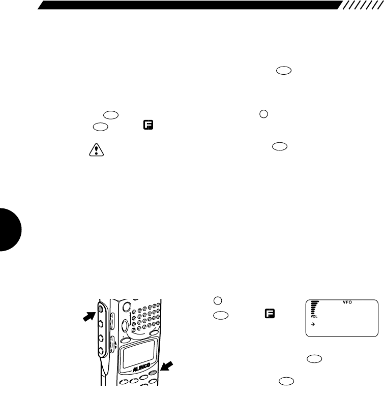
48
3Specify a priority interval.
Specify a priority interval in a range between 1 and 12 seconds in 1-second
steps using the UP/DOWN key, and then press the key (the initial setting is
5s).
The display will return to the PRIO menu. Point the arrow at END and then press
the key (Alternatively, you may press the key, and then press the
key with shown on the display).
Note: If you exit the PRIO menu by pressing the key, the changed setting is
canceled.
3.1.22 Setting search resume condition
(SRCH MODE)
For the DJ-X2000 to perform the Channel Scope function, its receiver is used for
searching the signals, and the sound will be intermit at the moment when the
search takes place.
This setting determines how often the search takes place in the Channel Scope
function. This is referred to as the “search mode”.
1Call up the CH SCOPE menu.
Press the key, and then
press the key with
shown on the display.
The CH SCOPE menu will
appear. Point the arrow at +CONFIG using the dial or
UP/DOWN key, and then press the key.
The CONFIG menu will appear. Point the arrow at +CH
SCOPE and then press the key.
ENT
TF
ENT
TF
HELP
SET
F
MODE
AUTO MW
MIC
A-B S
M NAME
STEPATTSET
POWER
PMS
VFOMR MW
A B
SET
KL
3
2
1
RF C
HELP
MONI
F
SRCH
LAMP
SQL VOL
DOWN UP
CLR
SKIP
F
ENT
TF
I NTERVAL
CONT I NUE
C
H
SCOPE
ENT
TF
ENT
TF
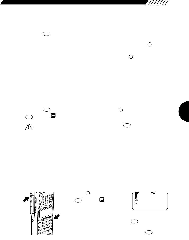
49
2Select a search resuming option.
Point the arrow at the desired option using the dial or UP/DOWN key, and then
press the key. The available options are described below (the initial setting
is INTERVAL):
SINGLE The search is carried out only once when the key is
pressed. It is not carried out a second time until the first
search is turned canceled and the key is pressed
again.
INTERVAL A search is carried out once every 10 seconds updating
the spectrum condition. Sound is muted the moment the
search takes place.
CONTINUE Searching is continuous and the spectrum condition is
renewed continuously. In this case, no sound is heard
from the DJ-X2000.
The display will return to the CH SCOPE menu. Point the arrow at END and then
press the key (Alternatively, you may press the key, and then press the
key with shown on the display).
Note: If you exit the CH SCOPE menu by pressing the key, the changed
setting is canceled.
3.1.23 Flash tune
The DJ-X2000 automatically tunes in to the detected radio frequency, allowing
you to instantaneously tune in to and receive unknown radio.
• Selecting the Flash tune.
The Flash tune is available in two modes, F TUNE and F COUNTER.
1Call up the F TUNE screen.
Press the key, and then press
the key with shown on
the display.
The F TUNE screen will appear.
Point the arrow at +SPECIAL using the dial or
UP/DOWN key, and then press the key.
The SPECIAL screen will appear. Point the arrow at +F
TUNE (+FLASH TUNE) and then press the key.
ENT
TF
ENT
TF
HELP
SET
F
MODE
AUTO MW
X2
MIC
SCRT PRIO
REC
CTCSS
F TUNE
A-B S
M NAME
TF
SKIP
STEPATT
SET
POWER
PMS
VFOMR MW
A B
SET
KL
3
6
9
8
0
5
2
1
4
CLR
ENT
MIC
SCN
RF C
HELP
7
MONI
F
SRCH
LAMP
SQL VOL
DOWN UP
CLR
SKIP
ENT
TF
F
ENT
TF
SRCH
SRCH
ENT
TF
FLASH
TUNE
F.
COUNTER
FLASH TUNE
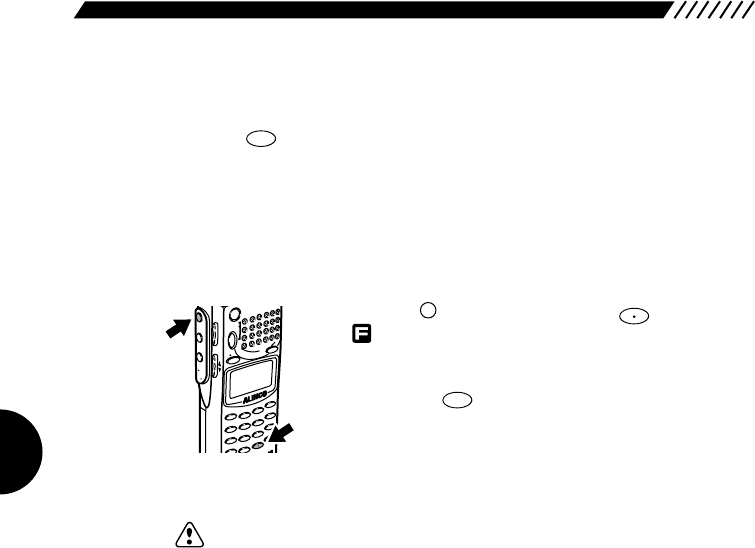
50
2Select the Flash tune.
Point the arrow at the desired option using the dial or UP/DOWN key, and then
press the key (the initial setting is F TUNE).
F TUNE Instantaneously checks for a radio frequency and
automatically tunes in to the detected frequency.
F COUNTER Check for a radio frequency and shows the detected
frequency in real time (the frequency resolution is
100 Hz).
• Starting the Flash tune
Press the key, and then press the key with
shown on the display. The Flash
tune will start.
Pressing the key cancels the Flash tune.
Note: • The operating frequencies in the F TUNE and F COUNTR modes ranges
from approximately 50 MHz to 1300 MHz. The Flash tune starts with input
of approximately -30 dB or more. However, if there is any strong radio or
noise than the targeted radio, the Flash tune may not be activated
depending on the frequency condition.
• This function is not applicable to intermittent radio in intervals of 0.1 second
or less, such as digital radio.
• The Flash tune is not valid for radio that fluctuates by 1 kHz or more.
• If the Flash tune is set during scanning in the PMS or MR mode, the
scanning is canceled.
CLR
SKIP
F TUNE
F
MODE
AUTO MW
MIC
SCRTPRIO
REC
CTCSS
F TUNE
A-B S
M NAME
TF
SKIP
STEPATTSET
PO
WER
PMS
VFOMR MW
A B
SET
KL
3
6
9
8
0
5
2
1
4
CLR
ENT
SCN
RF C
HELP
7
MONI
F
SRCH
LAMP
SQL VOL
DOWN UP
ENT
TF
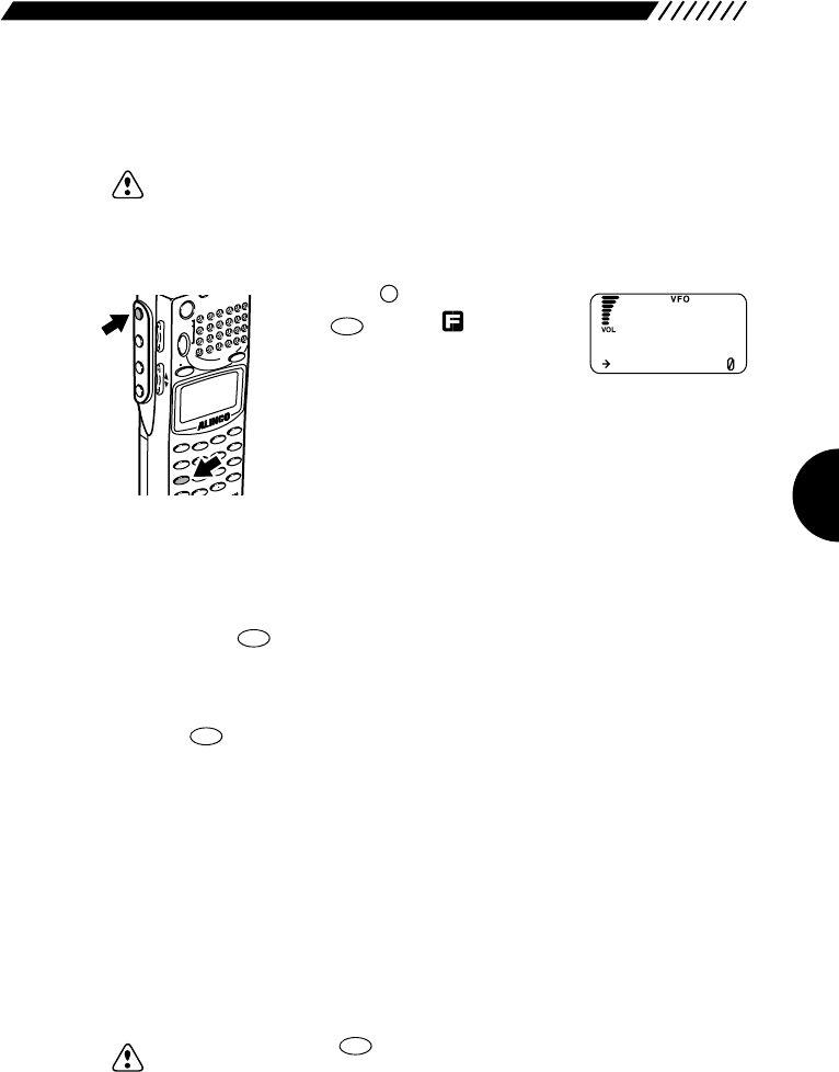
51
3.1.24 Descrambler
This function descrambles the scrambled voice signals.
Note: Only the NFM type radio signals can be descrambled.
1Call up the SET SCRAMBLE screen and then turn ON the
Descrambler. Press the key, and then press
the key with shown on
the display.
The SET SCRAMBLE screen will
appear. Point the arrow at ON using the UP/DOWN key.
2Control the carrier.
With the arrow pointing at ON, set the carrier to the state where the voice can be
recognized. The carrier can be increased or decreased in a range between 0
and 125 (the initial setting is 40).
If you press the key with the arrow pointing at ON, the normal screen
appears with the Descrambler being active.
• Canceling the Descrambler
Press the key. This will cancel the Descrambler.
• Priority in comparison with the CTCSS decoding function and A/B squelch
The Descrambler cannot be used with the CTCSS decoding function or A/B
squelch.
• If the A/B squelch is turned ON when the Descrambler is active, the A/B
squelch takes priority.
• The CTCSS decoding function cannot be used when the Descrambler or A/B
squelch is active.
• If the Descrambler is turned ON when the CTCSS decoding function is active,
the CTCSS decoding function remains disabled until the Descrambler is turned
OFF.
Note: • If you press the key to display the normal screen when the
Descrambler is active, the Descrambler is disabled for any radio type other
than the NFM.
• If “VOL” is blinking on the display when the Descrambler is active, the
sound volume can be controlled.
ENT
TF
CLR
SKIP
ENT
TF
7
SCRT
F
MODE
AUTO MW
MIC
SCRTPRIO
REC
CTCSS
F TUNE
A-B S
M NAME
TF
SKIP
STEPATT
SET
POWER
PMS
VFOMR MW
A B
SET
KL
3
6
9
8
0
5
2
1
4
R
ENT
SCN
RF C
HELP
7
MONI
F
SRCH
LAMP
SQL VOL
DOWN UP
ヒ
O
FF
O
N4
ワカイト゛ク
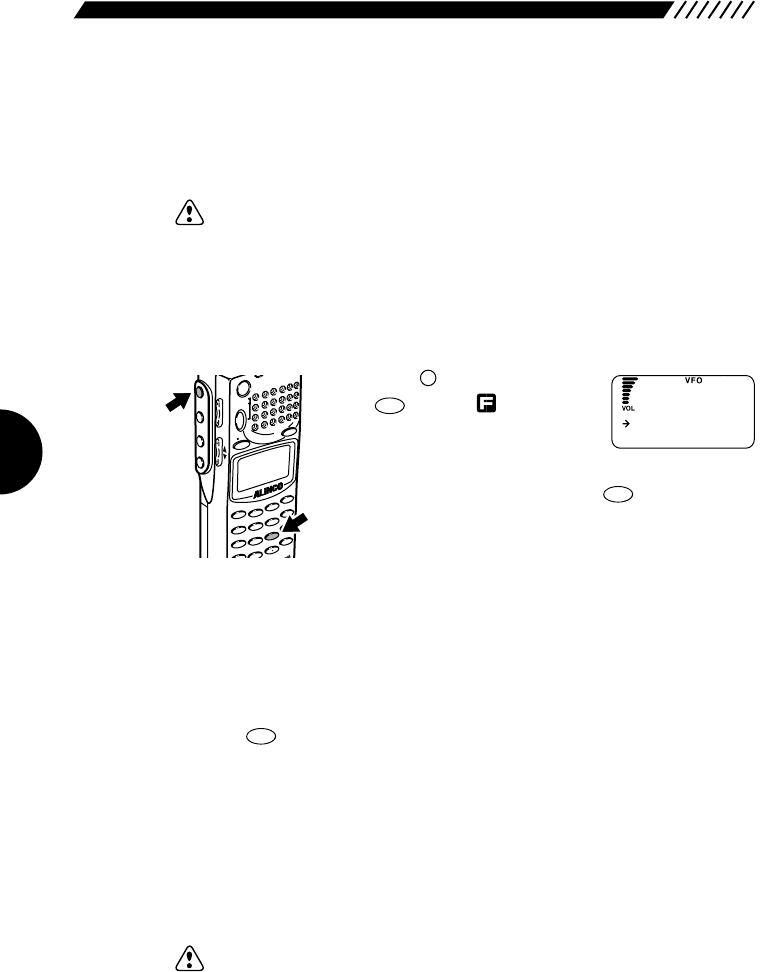
52
3.1.25 CTCSS decoding function
This function is used to receive CTCSS signals. It allows you to receive 38
waves of CTCSS signals and even select the reverse reception. The function is
also applicable to taxi radio.
Note: Only the NFM type radio can be received as CTCSS signals.
• Setting the reception of CTCSS signals
Specify the reception frequency of CTCSS signals and turn ON/OFF the
reception.
1Call up the CTCSS MANUAL screen.
Press the key, and then press
the key with shown on
the display.
The CTCSS SET menu will appear.
Point the arrow at +MANUAL using the dial or
UP/DOWN key, and then press the key.
2Select the reception frequency of CTCSS signal.
Point the arrow at ON using the UP/DOWN key, and then select the reception
frequency of CTCSS signals using the dial.
The range of selectable frequencies is between 76 and 254 Hz (the initial setting
is 88.5 Hz).
If you do not want to receive CTCSS signals, select OFF.
Press the key to complete the setting.
• Priority order in comparison with the Descrambler and A/B squelch
The CTCSS decoding function cannot be used with the Descrambler or A/B
squelch.
• If the Descrambler or A/B squelch is active, the CTCSS decoding function is
disabled.
• If the Descrambler or A/B squelch is turned ON when the CTCSS decoding
function is active, the CTCSS decoding function is disabled during its use.
Note: In the PMS or MR mode, when DIRECT WR is turned ON, this setting is
possible (the initial setting is ON). For further details, see “3.3.31 Directly
changing the settings” (page 63).
ENT
TF
ENT
TF
9
CTCSS
F
MODE
AUTO MW
MIC
SCRTPRIO
REC
CTCSS
F TUNE
A-B S
M NAME
TF
SKIP
STEPATT
SET
POWER
PMS
VFOMR MW
A B
SET
KL
3
6
9
8
0
5
2
1
4
R
ENT
SCN
RF C
HELP
7
MONI
F
SRCH
LAMP
SQL VOL
DOWN UP
C
O
FF
O
N88.5Hz
TCSS
M
ANUAL
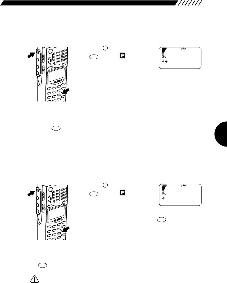
53
• CTCSS scanning
This function is used to scan for CTCSS signals.
1Call up the CTCSS SET menu.
Press the key, and then press
the key with shown on
the display.
The CTCSS SET menu will
appear.
2Start scanning
Point the arrow at CTCSS SCAN using the dial or UP/DOWN key, and then
press the key. This will start scanning.
Once CTCSS signals are detected, the scanning stops.
• CTCSS reversing
This function is used to reverse the CTCSS decoding function. When it is set to
ON, CTCSS signals of a mismatching frequency are received while those of a
matching frequency are not received.
1Call up the CTCSS REVERSE screen.
Press the key, and then press
the key with shown on
the display.
The CTCSS SET menu will
appear. Point the arrow at REVERSE using the dial or
UP/DOWN key, and then press the key.
2Select ON/OFF for the CTCSS reversing function.
Point the arrow at ON or OFF using the dial or UP/DOWN key, and then press
the key.
Note: This function may fail if signals are too weak or include too many noises.
ENT
TF
ENT
TF
9
CTCSS
F
MODE
AUTO MW
MIC
SCRTPRIO
REC
CTCSS
F TUNE
A-B S
M NAME
TF
SKIP
STEPATT
SET
POWER
PMS
VFOMR MW
A B
SET
KL
3
6
9
8
0
5
2
1
4
R
ENT
SCN
RF C
HELP
7
MONI
F
SRCH
LAMP
SQL VOL
DOWN UP
ENT
TF
9
CTCSS
F
MODE
AUTO MW
MIC
SCRTPRIO
REC
CTCSS
F TUNE
A-B S
M NAME
TF
SKIP
STEPATT
SET
POWER
PMS
VFOMR MW
A B
SET
KL
3
6
9
8
0
5
2
1
4
R
ENT
SCN
RF C
HELP
7
MONI
F
SRCH
LAMP
SQL VOL
DOWN UP
MANUA L
CTCSS SCAN
CTCSS SET
OFF
ON
REVERSE
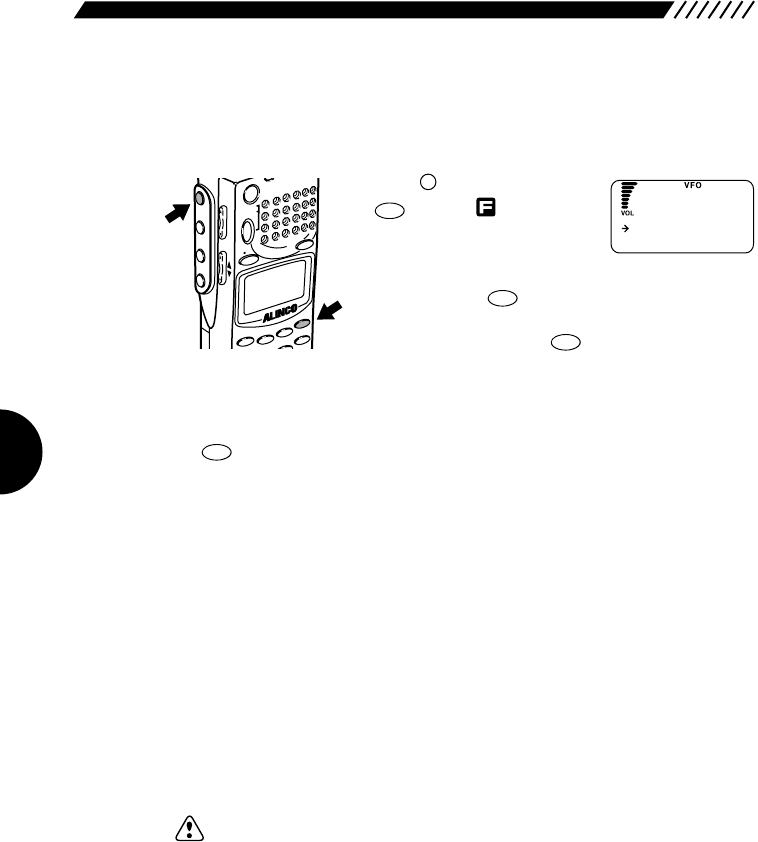
54
3.1.26 A/B squelch
This function is used to start squelch by detecting free-line signals.
1Call up the A/B SQ SET screen.
Press the key, and then press
the key with shown on
the display.
The menu will appear. Point the
arrow at +SPECIAL using the dial or UP/DOWN key,
and then press the key.
The SPECIAL menu will appear. Point the arrow at +A/B
SQ SET and then press the key.
2Select ON/OFF for A/B squelch.
Point the arrow at ON or OFF using the dial or UP/DOWN key, and then press
the key (the initial setting is OFF).
ON If modulation signals of 2300 Hz used for free-line signals are
detected, the squelch is activated and the sound is muted. If
those signals are no longer detected, the squelch is canceled.
OFF The A/B squelch is disabled.
• Priority order in comparison with the Descrambler and CTCSS decoding
function
The A/B squelch cannot be used with the Descrambler or CTCSS decoding
function.
• If the A/B squelch is turned ON when the Descrambler is active, the A/B
squelch takes priority.
• If the Descrambler or A/B squelch is active, the CTCSS decoding function is
disabled.
• If the A/B squelch is turned ON when the CTCSS decoding function is active,
the CTCSS decoding function is canceled during its use.
Note: • This function may fail if radio or modulation signals are too weak or include
too many noises.
• It is not applicable to free-line signals of any frequency other than 2300 Hz.
ENT
TF
ENT
TF
ENT
TF
HELP
SET
F
MODE
AUTO MW
MIC
A-B S
M NAME
STEPATTSET
POWER
PMS
VFOMR MW
A B
SET
KL
3
2
1
RF C
HELP
MONI
F
SRCH
LAMP
SQL VOL
DOWN UP
OFF
ON
A/B S
Q
SET
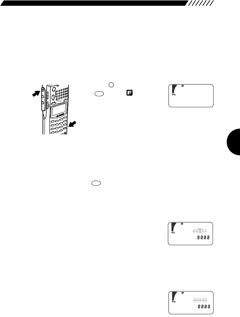
55
3.1.27 Transweeper
This function is used to detect a wireless microphone or any other bug using
radio and locate the place where it is installed. If you previously assign any
frequency expected for bugging purposes to the memory channel or auto
memory channel, the DJ-X2000 will scan for that frequency. The settings for
bank link and channel skipping will become valid.
1Turn ON the transweeper.
Press the key, and then press
the key with shown on
the display.
The transweeper will start.
The scanning varies depending on the basic mode in
use.
VFO mode The scanning is performed from the currently received
frequency toward higher frequencies. The scanning
direction is changed using the dial or UP/DOWN key.
MR mode Only the specified bank is scanned. The settings for
bank link and channel skipping become valid. Pressing
the key starts the scanning.
PMS mode The scanning is performed only within the programmed
scanning range that you have specified.
2Check for bugging.
In this state, control the sound volume and the orientation
of the DJ-X2000. If the existence of any bug is detected,
the display changes as shown here.
3Search for the location of the bug while slowly bringing the DJ-X2000
closer to that bug.
You can find the distance to the location of the bug according to the changes on
the display.
• As the DJ-X2000 comes closer to the bug
SCN
A~B S
ENT
TF
F
MODE
AUTO MW
X2
MIC
SCRTPRIO
REC
CTCSS
F TUNE
A-B S
M NAME
TF
SKIP
STEPATTSET
POWER
RX/ST
PMS
VFOMR MW
A B
SET
KL
3
6
9
8
0
5
2
1
4
CLR
ENT
MIC
SCN
RF C
HELP
7
MONI
F
SRCH
LAMP
SQL VOL
DOWN UP
T
NNO FOU D
F
A
(
1 154.
)
_
,,
A
(
1 154.
)
_
,,
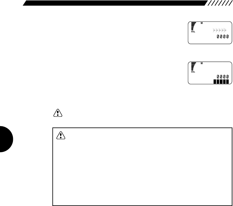
56
CAUTION: • The effective range of sound monitoring for bugs is normally
between approximately 1 m and 5 m.
• The transweeper is greatly affected by the intensity of radio from
the bug and the sensitivity of the microphone. It may malfunction
or fail depending on the ambient conditions (where there are too
many echoes).
• If the DJ-X2000 is suddenly moved during its transweeper process,
the Doppler effect causes a malfunction.
• The transweeper may not work normally depending on the relation
between the orientation of the speaker and the location of the bug.
• This function does not work normally when radio with modulation
signals of 2300 Hz is received.
• As the DJ-X2000 goes away from the bug
• The number of ■shown at the lower right corner of the
display tells you the distance to the location of the bug.
Each ■represents approximately 1 m. For example, 5
■show that the bug is located more than 5 m away.
Note: If no bug is found after the specified range has been scanned, the message
“NO FOUND” appears on the display.
A
(
1 154.
)
_
,,
A
(
1 154.
)
_
,,
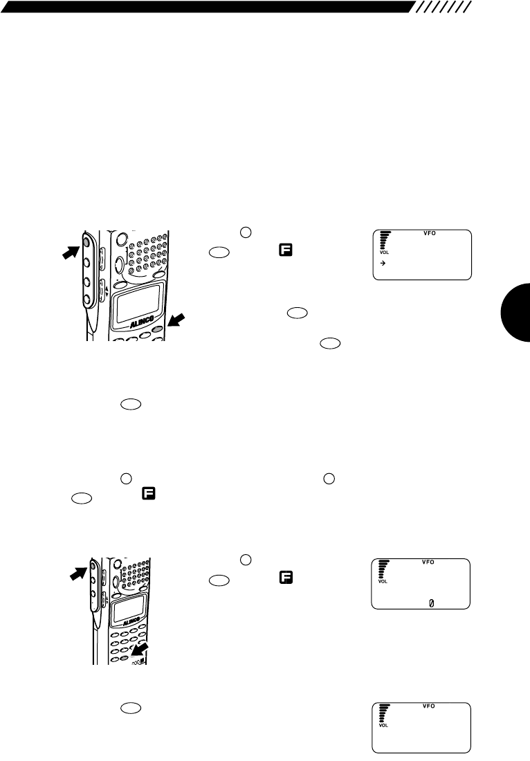
57
3.1.28 Recording function
This function is used to record the received sound or sound from the speaker
using the internal IC. It allows you to record such sound for 160 seconds
maximum. Recording, playback, and erasing can be repeated as many times as
you like.
• Selecting a source
Specify which sound is recorded, the received sound or the sound from the
speaker.
1Call up the REC screen.
Press the key, and then press
the key with shown on
the display.
The menu will appear. Point the
arrow at +SPECIAL using the dial or UP/DOWN key,
and then press the key.
The SPECIAL screen will appear. Point the arrow at
+REC and then press the key.
2Select the received sound or the sound from the speaker.
Point the arrow at the desired option using the dial or UP/DOWN key, and then
press the key (the initial setting is MIC).
RX AF The received sound is recorded.
MIC The sound from the speaker is recorded.
The display will return to the SPECIAL screen. Point the arrow at END and then
press the key (Alternatively, you may press the key, and then press the
key with shown on the display).
• Recording the sound
1Call up the recording screen.
Press the key, and then press
the key with shown on
the display.
The recording screen will appear.
2Start the recording
Press the key. The recording will start and the
elapsed time will appear on the display. The sound can
be recorded for 160 seconds maximum.
1
MODE
0
REC
F
MODE
AUTO MW
JX2
MIC
SCRTPRIO
REC
CTCSS
F TUNE
A-B S
M NAME
TF
SKIP
STEPATTSET
POWE
R
PMS
VFOMR MW
A B
SET
KL
3
6
9
8
0
5
2
1
4
CLR
ENT
MIC
SCN
RF C
HELP
7
MONI
F
SRCH
LAMP
SQL VOL
DOWN UP
ENT
TF
F
F
ENT
TF
ENT
TF
ENT
TF
HELP
SET
F
MODE
M NAME
STEPATTSET
POW
ER
PMS
VFOMR MW
A B
SET
KL
3
2
RFC
HELP
MONI
F
SRCH
LAMP
SQL VOL
DOWN UP
RX AF
MIC
REC
1
2
STOP
3
PLAY
.
PUASE DE
L
REC
RECORD I NG
5s
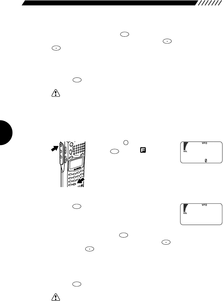
58
3Stop or pause the recording.
To stop the recording, press the key.
To pause (temporarily stop) the recording, press the key. If you press the
key again, the recording is resumed.
When the recording time reaches 160 seconds, “END” appears on the display
and the recording stops automatically.
4Exit the recording mode.
Press the key.
Note: • Only a single session of sound can be recorded.
• No other function can be used during the recording.
• The sound volume can be controlled in the recording mode.
• Sound can be repeatedly recorded approximately 10,000 times.
• The RX AF recording starts when sound signal is received.
• Playing back the recorded sound
1Call up the recording screen.
Press the key, and then press
the key with shown on
the display.
The recording screen will appear.
2Start the playback.
Press the key. The playback will start and the
elapsed time will appear on the display.
3Stop or pause the playback.
To stop the playback, press the key.
To pause (temporarily stop) the playback, press the key.
If you press the key again, the playback is resumed.
After all the recorded sound has been played back, “END” appears on the
display and the playback stops automatically.
4Exit the recording mode.
Press the key.
Note: • No other function can be used during playback.
• No battery backup is required to store the recorded data.
• If the all reset function is used, the recorded data is erased.
CLR
SKIP
F TUNE
2
STEP
3
ATT
0
REC
F
MODE
AUTO MW
JX2
MIC
SCRTPRIO
REC
CTCSS
F TUNE
A-B S
M NAME
TF
SKIP
STEPATTSET
POWE
R
PMS
VFOMR MW
A B
SET
KL
3
6
9
8
0
5
2
1
4
CLR
ENT
MIC
SCN
RF C
HELP
7
MONI
F
SRCH
LAMP
SQL VOL
DOWN UP
CLR
SKIP
F TUNE
2
STEP
1
2
STOP
3
PLAY
.
PUASE DE
L
REC
PLAYING
5s
F TUNE
F TUNE
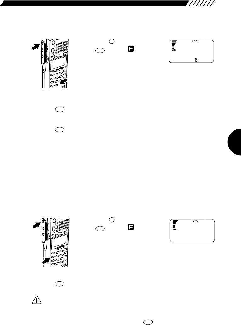
59
• Erasing the recorded data
1Call up the recording screen.
Press the key, and then press
the key with shown on
the display.
The recording screen will appear.
2Erase the recorded data.
Press the key. The recorded data will be erased.
3Exit the recording mode.
Press the key.
3.1.29 Sound pickup
The sound picked up through the microphone can be heard using an earphone
or external speaker.
• Picking up sound
1Connect an earphone or external speaker to the SP terminal on the
top of the DJ-X2000.
2Start picking up sound.
Press the key, and then press
the key with shown on
the display.
The sound pickup will start.
• Canceling the sound pickup
Press the key.
Note: • If no earphone or external speaker is connected, the sound pickup does
not function. If you try to use this function without connecting any earphone
or external speaker, the beep sound is emitted and the message “INSERT
EARPHONE” appears on the display.
• Only the POWER switch, VOL key, and key are valid during the
sound pickup.
• If howling occurs, turn down the volume or keep the earphone or external
speaker away from the microphone.
CLR
SKIP
CLR
SKIP
4
MIC
F
MODE
AUTO MW
JX2
MIC
SCRTPRIO
REC
CTCSS
F TUNE
A-B S
M NAME
TF
SKIP
STEPATTSET
POWE
R
PMS
VFOMR MW
A B
SET
KL
3
6
9
8
0
5
2
1
4
CLR
ENT
MIC
SCN
RF C
HELP
7
MONI
F
SRCH
LAMP
SQL VOL
DOWN UP
CLR
SKIP
0
REC
0
REC
F
MODE
AUTO MW
JX2
MIC
SCRTPRIO
REC
CTCSS
F TUNE
A-B S
M NAME
TF
SKIP
STEPATTSET
POWE
R
PMS
VFOMR MW
A B
SET
KL
3
6
9
8
0
5
2
1
4
CLR
ENT
MIC
SCN
RF C
HELP
7
MONI
F
SRCH
LAMP
SQL VOL
DOWN UP
1
2
STOP
3
PLAY
.
PUASE DE
L
REC
M
The sound
Can be heard
IC
O
N
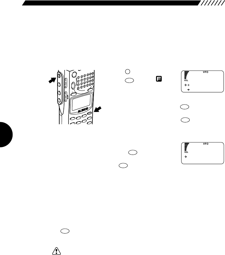
60
3.1.30 Transceiver function
This function allows you to use the DJ-X2000 as a transceiver. The <SRCH> key
located on the left side of the DJ-X2000 will work as the PTT (Press to Talk) key.
• Entering the TRANCEIVER mode
1Call up the TRANCEIVER screen.
Press the key, and then
press the key with
shown on the display.
The TRANCEIVER menu will
appear. Point the arrow at +SPECIAL using the dial or
UP/DOWN key, and then press the key.
The SPECIAL menu will appear. Point the arrow at
+TRANCEIVER and then press the key.
2Set the function of the PTT (SRCR) key.
Point the arrow at +PTT MODE using the dial or
UP/DOWN key, and then press the key.
The PTT MODE screen will appear. Point the arrow at
OFF or ON and then press the key.
OFF Transmission is performed while the PTT (SRCH) key is being
held down.
ON Pressing the PTT (SRCH) key toggles between transmission and
reception.
The display will return to the TRANCEIVER menu.
3Activate the transceiver function.
Point the arrow at +TR MODE using the dial or UP/DOWN key, and then press
the key.
The transceiver function will be activated.
Note: • The transceiver function is only available in the World version.
ENT
TF
ENT
TF
ENT
TF
ENT
TF
ENT
TF
HELP
SET
F
MODE
AUTO MW
MIC
CTCSS
A-B S
M NAME
STEPATTSET
POWER
PMS
VFOMR MW
A B
SET
KL
3
6
5
2
1
4
SCN
RF C
HELP
MONI
F
SRCH
LAMP
SQL VOL
DOWN UP
TR
モート゛
PTT
モート゛
トランシーハ゛
OFF
ON
PTT
モート゛
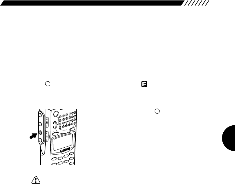
61
• Transmission and reception
1Select the frequency you want to receive.
The frequency can be selected using the dial or UP/DOWN key. However, the
following limitations apply:
Radio type NFM only
Frequency range 250.000 MHz to 259.975 MHz
Frequency step Fixed at 25 kHz
When is shown on the display by pressing the key, the frequency can be
increased or decreased in steps of 250 kHz using the dial or UP/DOWN key.
2Perform transmission.
In the TRANCEIVER mode, the key located on the
left side of the DJ-X2000 works as the PTT key.
If you speak to the microphone when the PTT key is ON,
the voice can be transmitted at the currently received
frequency.
The status of the PTT key can be selected from ON and
OFF.
Note: • Since the transmission uses only weak signals, no license for an amateur
radio station or the like is required.
• For the same reason, no antenna for weak transmission is connected to the
BNC connector.
SRCH
MODE
AUTO MW
MIC
CTCSSA-B S
M NAME
STEPATTSET
POWERR
PMS
VFOMR MW
A B
SET
KL
3
6
5
2
1
4
SCN
RF C
HELP
MONI
F
SRCH
LAMP
SQL VOL
DOWN UP
F
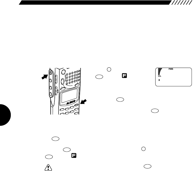
62
3.1.31 Directly changing the settings
This function allows you to enable/disable the direct changes of the settings for
radio type, frequency step, attenuator, and CTCSS decoding function in the MR
or PMS modes. When it is turned ON, the settings for radio type, frequency step,
attenuator, and CTCSS decoding function can be directly changed in the
currently displayed MR or PMS mode.
1Call up the DIRECT WR screen.
Press the key, and then press
the key with shown on
the display.
The menu will appear. Point the
arrow at +CONFIG using the dial or UP/DOWN key, and
then press the key.
The CONFIG screen will appear. Point the arrow at
+DIRECT WR and then press the key.
2Selecting ON/OFF for DIRECT WR.
Point the arrow at ON or OFF using the dial or UP/DOWN key, and then press
the key (the initial setting is OFF).
The display will return to the CONFIG screen. Point the arrow at END and then
press the key (Alternatively, you may press the key, and then press the
key with shown on the display).
Note: If you exit the CONFIG screen by pressing the key, the changed
settings are canceled.
CLR
SKIP
ENT
TF
F
ENT
TF
ENT
TF
ENT
TF
ENT
TF
HELP
SET
F
MODE
AUTO MW
MIC
CTCSS
A-B S
M NAME
STEPATTSET
POWER
PMS
VFOMR MW
A B
SET
KL
3
6
5
2
1
4
SCN
RF C
HELP
MONI
F
SRCH
LAMP
SQL VOL
DOWN UP
O
N
O
FF
DI
R
ECT
W
R
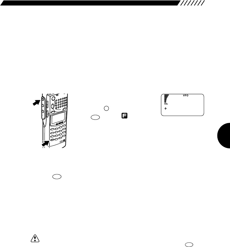
63
3.2 Functions in the VFO mode
This section describes various functions available in the VFO mode.
3.2.1 VFO link function
This function is used to synchronously change two VFO frequencies, the
currently received frequency and another frequency.
1Call up the LINK SET screen.
Specify frequencies in bands A
and B of VFO.
Press the key, and then press
the key with shown on
the display.
2Select a type of the VFO link function.
Point the arrow at the desired option using the dial or UP/DOWN key, and then
press the key (the initial setting is LINK OFF).
AUTO LINK The frequencies in bands A and B interlock and change
at the interval that was set using the auto link function.
USER LINK Both bands A and B are displayed in capital letters and
the VFO link function becomes active. As the frequency
on the upper line of the display is changed, the one on
the lower line changes simultaneously.
LINK OFF The VFO link function is canceled.
Note: The frequency on the upper line may exceed 2149.999950 MHz (the upper
limit for the DJ-X2000) when it is changed. In this case, press the key
toggle between bands A and B. The band shown on the upper line will be
switched to the lower line. The band shown on the lower line (exceeding
2149.9999 MHz) will be included in a range between 0.1 MHz and
2149.999 MHz and then switched to the upper line while maintaining the
difference between the two frequencies. The VFO link function is not
canceled.
A=B
VFO
ENT
TF
CLR
SKIP
F
MODE
AUTO MW
INTELLIGENT
RECEIVER
DJ-X2
MIC
SCRTPRIO
REC
CTCSS
F TUNE
A-B S
M NAME
TF
SKIP
STEPATTSET
POWERRX
/ST
PMS
VFOMR MW
A B
SET
KL
3
6
9
8
0
5
2
1
4
CLR
ENT
MIC
SCN
RF C
HELP
7
MONI
F
SRCH
LAMP
SQL VOL
DOWN UP
AUT
O
LINK
USER L I NK
LINK SET
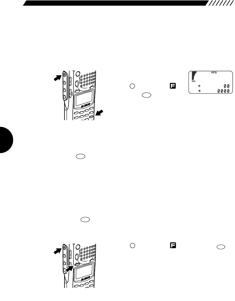
64
3.2.2 Scanning between VFO's A and B
(AB SCAN)
This function is for scanning the band between the current frequencies of VFO-A
and VFO-B.
• To scan between VFO’s A and B
Set frequency on each band A
and B.
Press the key to display ,
Then press the key.
This will start scanning and will display the arrow next to
both bands.
Scanning direction can be changed using the dial or the UP/DOWN key.
• To cancel AB scan
Press the key. This will cancel AB scanning.
3.2.3 Copying frequencies from
memories to the VFO
You can copy frequencies from a memory channel to the VFO.
1Call up the frequency in memory.
Press the key to get the MR mode. Then set the memory bank No. and
channel No. you want .
2Copy the frequency into the VFO.
Press the key to display , followed by the
key. The frequency in the selected memory channel will
be displayed on the upper line (currently used) band.
A=B
VFO
F
MODE
AUTO MW
IC
A-B S
M NAME
STEPATT
SET
PO
WER
PMS
VFOMR MW
A B
SET
KL
3
2
1
RF C
HELP
MONI
F
SRCH
LAMP
SQL VOL
DOWN UP
MRMW
SCN
A~B S
SCN
A~B S
F
MODE
AUTO MW
MIC
SCRTPR
IO CTCSSA-B S
M NAME
T
F
STEPATT
SET
PO
WER
PMS
VFOMR MW
A B
SET
KL
3
6
9
5
2
1
4
SCN
RF C
HELP
MONI
F
SRCH
LAMP
SQL VOL
DOWN UP
N
A 145.34
b 144.
F
M
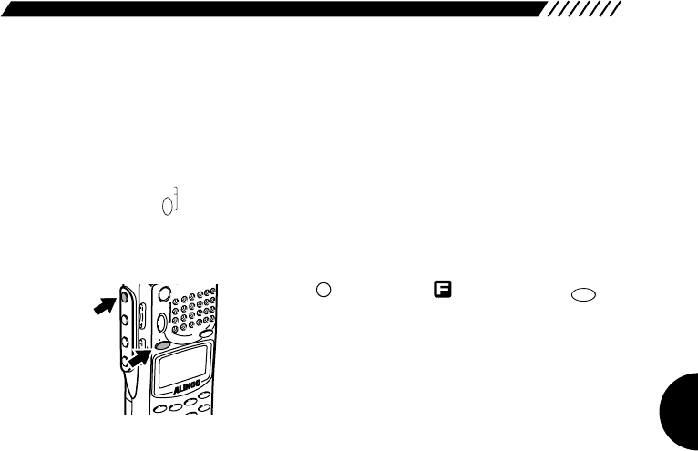
65
3.2.4 Copying frequencies from the PMS
mode to the VFO
You can copy frequencies in the PMS mode to the VFO.
1Call up the frequency in memory.
Press the key to get the PMS mode. Then set the program bank No. you
want to display in the VFO mode.
2Copy the frequency into the VFO.
Press the key to display , followed by the
key. The frequency in the selected program bank will be
displayed on the upper line (currently used) band the
instant that scanning picks it up.
A=B
VFO
F
MODE
AUTO MW
IC
A-B S
M NAME
STEPATT
SET
PO
WER
PMS
VFOMR MW
A B
SET
KL
3
2
1
RF C
HELP
MONI
F
SRCH
LAMP
SQL VOL
DOWN UP
PMS
SET
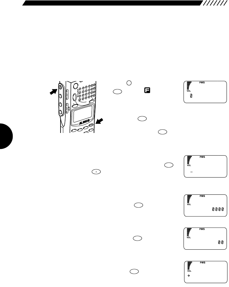
66
3.3 PMS mode functions
This section explains operations in the PMS mode.
3.3.1 Programmed scan operations
This section is for programmed scan operations.
1Call up the PMS SET screen.
Press the key, and then press
the key with shown on
the display.
The menu will appear. Point the
arrow at +PMS using the dial or UP/DOWN key, and
then press the key.
The PMS screen will appear. Point the arrow at +PMS
SET and then press the key.
2Select the bank on which you want to store the scanning program.
Using the dial or numeric keys, select the bank on which
you want to store the scanning program. Press the
key (Pressing the key toggles between the
uppercase P and the lowercase p).
3Specify the frequency to start the scanning.
Using numeric keys, enter the frequency at which you
want to start the scanning. Press the key.
4Specify the frequency to end the scanning.
Using numeric keys, enter the frequency at which you
want to end the scanning. Press the key.
5Select a radio type.
Point the arrow at the desired radio type using the dial or
UP/DOWN key, and then press the key.
ENT
TF
ENT
TF
ENT
TF
F TUNE
ENT
TF
ENT
TF
ENT
TF
HELP
SET
F
MODE
AUTO MW
MIC
A-B S
M NAME
STEPATTSET
POWER
PMS
VFOMR MW
A B
SET
KL
3
2
1
RF C
HELP
MONI
F
SRCH
LAMP
SQL VOL
DOWN UP
S
P
----
.
----
--------
etPMS BANK
S
p1
----
.
----
--------
etPMS BANK
S
p1 82.
--------
etPMS START
S
p1 145.34
etP
M
SEND
AUT
O
M
O
DE
AM
MO
DE
W
FM
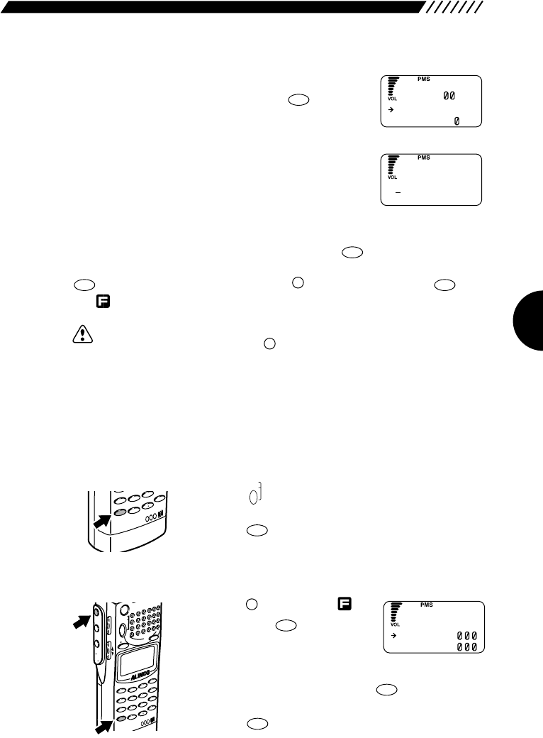
67
6Select a frequency step.
Point the arrow at the desired frequency step using the
dial or UP/DOWN key, and then press the key.
7Give a name to the program.
Select each character by turning the dial and then
establish it by pressing the DOWN key. The established
character can be canceled by pressing the UP key. Up
to 8 characters may be entered for the name.
8Store the scanning program.
After you have finished entering the name, press the key. The display
will return to the PMS menu. Point the arrow at END and then press the
key (Alternatively, you may press the key, and then press the key
with shown on the display).
Note: In naming the program, you can move 11 characters ahead by turning the
dial while holding down the key.
3.3.2 Setting scan pass-frequency
This setting specifies frequencies to be passed in the scanning operation
regardless of signal presence. As many as 50 pass frequencies can be set in a
single program bank.
• To set pass frequencies
Press the key to get the PMS mode. Then set the
program bank where pass frequencies are to be set.
Press the key whenever the program stops on a
frequency you want to pass.
• To clear pass settings
Press the key to display ,
followed by the key. This will
display the PASS EDIT display.
Then move the arrow to pass
frequency settings you want to clear, using the dial or
the UP/DOWN keys, and press the key. The
selected frequency will be disappear from the display.
Press the key to exit.
ENT
TF
0
REC
CLR
SKIP
F
MODE
AUTO MW
INTELLIGENT
RECEIVER
DJ-X2
MIC
SCRT PRIO
REC
CTCSS
F TUNE
A-B S
M NAME
TF
SKIP
STEPATT
SET
POWER
PMS
VFOMR MW
A B
SET
KL
3
6
9
8
0
5
2
1
4
CLR
ENT
MIC
SCN
RF C
HELP
7
MONI
F
SRCH
LAMP
SQL VOL
DOWN UP
CLR
SKIP
PMS
SET
INTELLIGENT
RECEIVER
DJ-X2
SCRTPRIO
REC
CTC
F TUNETF
SKIP
9
8
0
4
CLR
ENT
MIC
7
F
ENT
TF
F
ENT
TF
ENT
TF
ENT
TF
AUTO STEP
5Hz
STEP 1 KHz
S
ABCDEFGH I JK
etP
M
SNA
M
E
85.1
153.6
PASS ED I T
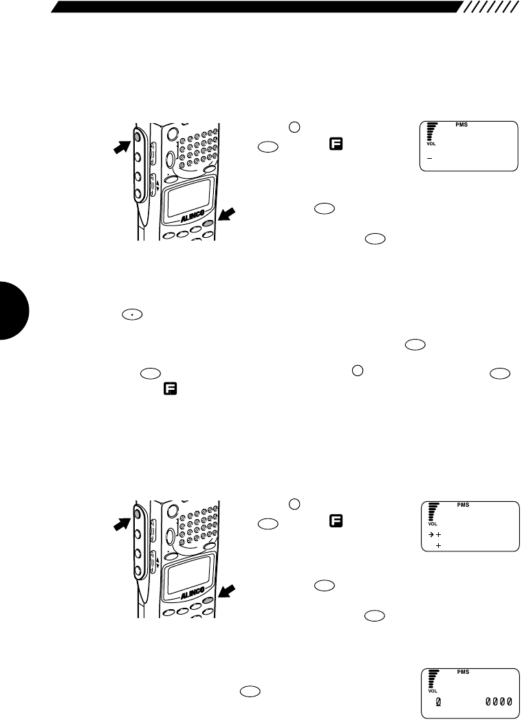
68
3.3.3 Setting program link
This function lets you scan a combination of frequency ranges.
1Call up the PMS LINK screen.
Press the key, and then press
the key with shown on
the display.
The menu will appear. Point the
arrow at +PMS using the dial or UP/DOWN key, and
then press the key.
The PMS screen will appear. Point the arrow at +PMS
LINK and then press the key.
2Enter a program bank number.
Using a numeric key, enter the program number you want to link. Pressing the
key toggles between the uppercase P and the lowercase p. To link all the
programs, enter all the numbers from 0 to 9.
After you have finished entering the number(s), press the key.
The display will return to the PMS menu. Point the arrow at END and then press
the key (Alternatively, you may press the key, and then press the
key with shown on the display).
3.3.4 Copying scan programs
This function copies scan programs from one bank to another.
1Call up the PMS EDIT screen.
Press the key, and then press
the key with shown on
the display.
The menu will appear. Point the
arrow at +PMS using the dial or UP/DOWN key, and
then press the key.
The PMS screen will appear. Point the arrow at +PMS
EDIT and then press the key.
2Call up the COPY screen.
Point the arrow at +COPY using the dial or UP/DOWN
key, and then press the key.
ENT
TF
ENT
TF
ENT
TF
HELP
SET
F
MODE
AUTO MW
MIC
A-B S
M NAME
STEPATTSET
POWER
PMS
VFOMR MW
A B
SET
KL
3
2
1
RF C
HELP
MONI
F
SRCH
LAMP
SQL VOL
DOWN UP
ENT
TF
F
ENT
TF
ENT
TF
F TUNE
ENT
TF
ENT
TF
HELP
SET
F
MODE
AUTO MW
MIC
A-B S
M NAME
STEPATTSET
POWER
PMS
VFOMR MW
A B
SET
KL
3
2
1
RF C
HELP
MONI
F
SRCH
LAMP
SQL VOL
DOWN UP
P
P
----------
p
----------
M
SBankLink
C
O
PY
MO
VE
P
M
SEDIT
C
P82.
OPY FROM
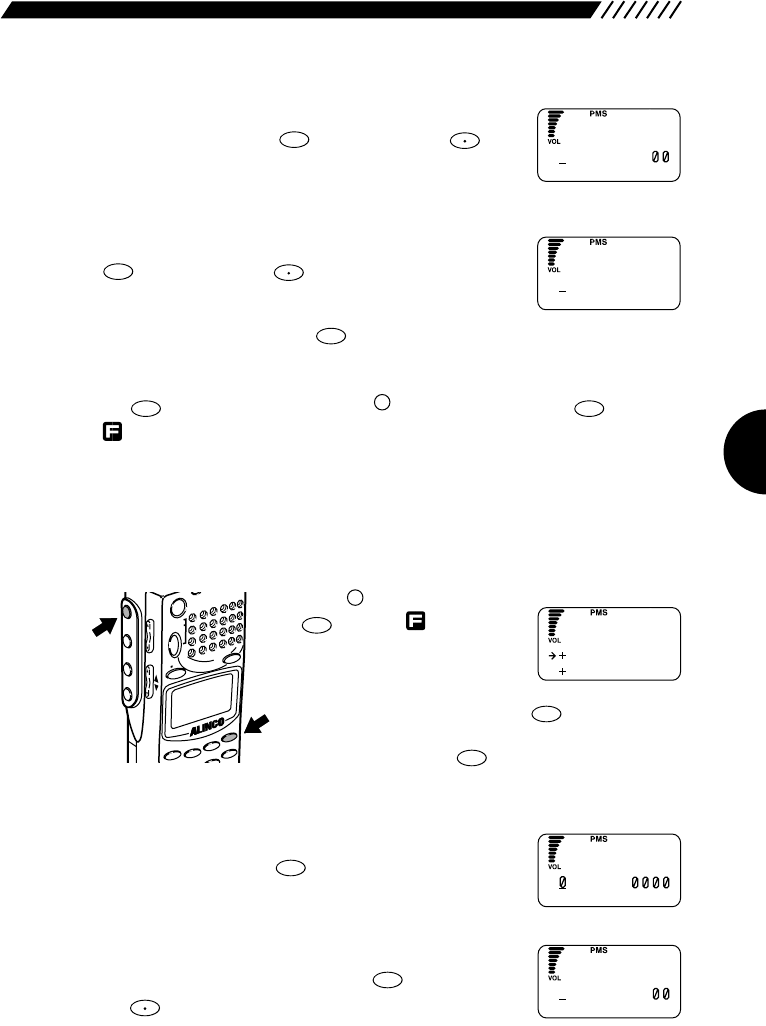
69
3Select a source program.
Using the dial or a numeric key, select the program you
want to copy. Press the key (pressing the key
toggles between the uppercase P and lowercase p).
4Select a destination program.
Using the dial or a numeric key, select the program to
which you want to copy the source program. Press the
key (pressing the key toggles between the
uppercase P and the lowercase p).
To retry the setting, press the key.
The display will return to the PMS EDIT screen. Point the END and then press
the key (Alternatively, press the key, and then press the key with
shown on the display).
3.3.5 Moving a scanning program
The selected scanning program may be moved to another program number.
1Call up the PMS EDIT screen
Press the key, and then press
the key with shown on
the display.
The menu will appear. Point the
arrow at +PMS using the dial or
UP/DOWN key, and then press the key.
The PMS screen will appear. Point the arrow at +PMS
EDIT and then press the key.
2Call up the MOVE screen.
Point the arrow at +MOVE using the dial or UP/DOWN
key, and then press the key.
3Select the program you want to move.
Using the dial or a numeric key, select the program
number you want to move. Press the key (Pressing
the key toggles between the uppercase P and the
lowercase p).
F TUNE
ENT
TF
ENT
TF
ENT
TF
ENT
TF
HELP
SET
F
MODE
AUTO MW
MIC
A-B S
M NAME
STEPATTSET
POWER
PMS
VFOMR MW
A B
SET
KL
3
2
1
RF C
HELP
MONI
F
SRCH
LAMP
SQL VOL
DOWN UP
ENT
TF
F
ENT
TF
CLR
SKIP
F TUNE
ENT
TF
F TUNE
ENT
TF
C
P1 145 . 34
OPY FROM
C
P2
----
.
----
--------
OPY TO
C
O
PY
MO
VE
P
M
SEDIT
M
P82.
OVE FROM
M
P1 145.34
OVE FROM
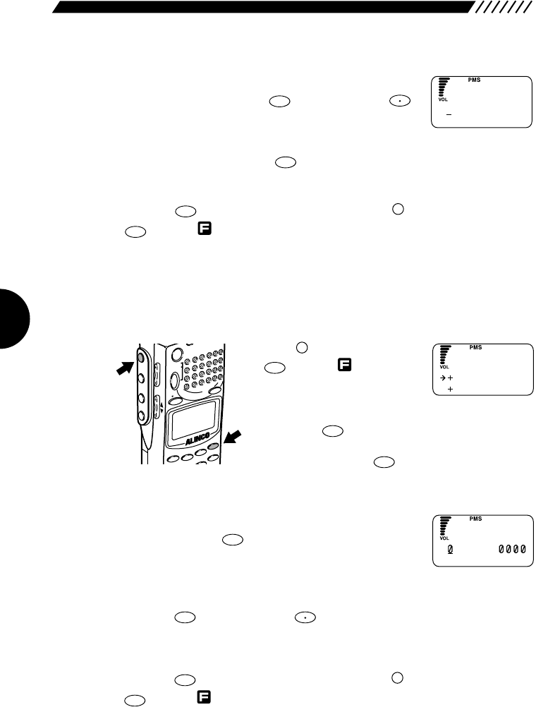
70
4Select the desired destination program.
Using the dial or a numeric key, select the destination
program number. Press the key (Pressing the
key toggles between the uppercase P and the lowercase
p).
To retry the setting, press the key.
The display will return to the PM EDIT screen. Point the arrow at END and then
press the key (Alternatively, you may press the key, and then press the
key with shown on the display).
3.3.6 Deleting scan programs
This function deletes scan programs from the program banks.
1Call up the PMS EDIT screen.
Press the key, and then press
the key with shown on
the display.
The menu will appear. Point the
arrow at +PMS using the dial or UP/DOWN key, and
then press the key.
The PMS screen will appear. Point the arrow at +PMS
EDIT and then press the key.
2Call up the DEL screen.
Point the arrow at +DEL using the dial or UP/DOWN key,
and then press the key.
3Select the program you want to delete.
Using the dial or a numeric key, select the program number you want to delete.
Press the key (Pressing the key toggles between the uppercase P
and the lowercase p).
The display will return to the PMS EDIT screen. Point the arrow at END and
press the key (Alternatively, you may press the , and then press the
key with shown on the display).
ENT
TF
F
ENT
TF
F TUNE
ENT
TF
ENT
TF
ENT
TF
ENT
TF
HELP
SET
F
MODE
AUTO MW
MIC
A-B S
M NAME
STEPATTSET
POWER
PMS
VFOMR MW
A B
SET
KL
3
2
1
RF C
HELP
MONI
F
SRCH
LAMP
SQL VOL
DOWN UP
ENT
TF
F
ENT
TF
CLR
SKIP
F TUNE
ENT
TF
M
P2
----
.
----
--------
OVE TO
C
O
PY
MO
VE
P
M
SEDIT
D
P82.
EL
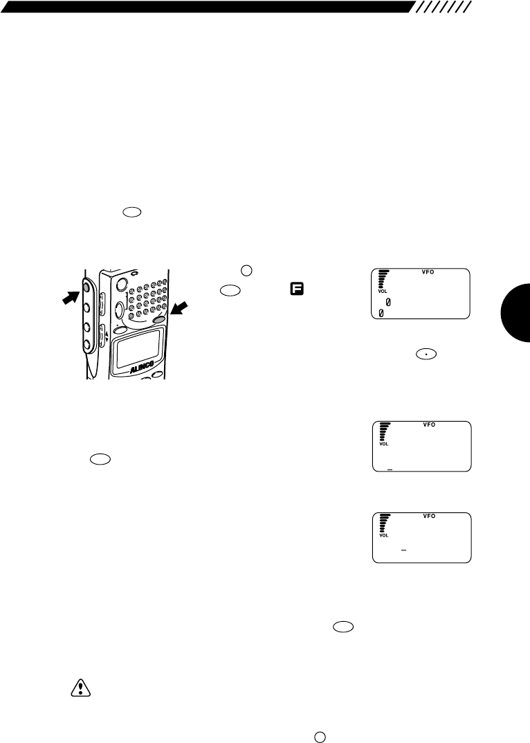
71
3.4 MR mode functions
This section explains operations into the MR mode.
3.4.1 Memorizing frequencies
This function saves selected frequencies into memory channels.
1Set the frequency you want to memorize, in the VFO mode.
Press the key to get the VFO mode. Then, set the frequency on the top line
(currently used) band.
2Select the bank number to which you want to assign a frequency.
Press the key, and then press
the key with shown on
the display.
The SET MR screen will appear.
Select the bank number using the dial or a numeric key,
and then press the DOWN key (Pressing the key
toggles from the bank groups A through E).
3Select a memory channel.
Using the dial or a numeric key, select the channel
number to which you want to assign the frequency. Press
the key.
4Give a name to the memory channel.
Select each character by turning the dial, and then
establish it by pressing the DOWN key. The established
character can be canceled by pressing the UP key. Up
to 8 characters may be entered for the name.
5Store the memory channel.
After you have finished entering the name, press the key. The frequency
will be assigned to the selected memory channel, and then the display will return
to the VFO mode.
Note: • The settings for the radio, frequency step, attenuator, and CTCSS
decoding function, which were completed in the VFO mode, will be stored
on the memory channel.
• In naming the memory channel, you can move 11 characters ahead by
turning the dial while holding down the key.
F
ENT
TF
ENT
TF
F TUNE
MRMW
F
ODE
NAME
STEP
ATTSET
POWER
RX/ST
PMS
VFOMR MW
A B
SET
HELP
MONI
F
SRCH
LAMP
SQL VOL
DOWN UP
A=B
VFO
S
A
----
.
----
1
--------
ET MR
S
A2
----
.
----
12
--------
ET MR
S
ABCDEFGH I JK
ABC
et
M
RNA
M
E
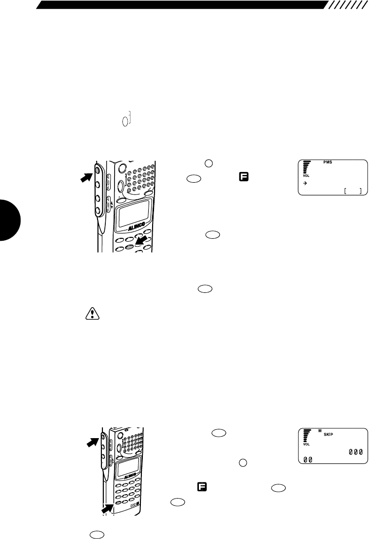
72
3.4.2 Setting the auto memory write
function
This function is used to automatically assign the frequency that has been
received during scanning in the PMS mode, to the memory bank.
1Call up the scanning program.
Press the key to enter the PMS mode. Select a program bank number. The
programmed scanning will start.
2Set the auto memory write function.
Press the key, and then press
the key with shown on
the display. The AUTO MW
screen will appear.
Point the arrow at START using the UP/DOWN key, and
select a program bank using the dial.
Press the key. The programmed scanning will
start and the received frequency will be assigned to the
automatically selected memory bank.
To stop the auto memory write function, point the arrow at STOP on the AUTO
MW screen, and then press the key.
Note: The settings for the radio type, frequency step, attenuator, and CTCSS
decoding function, which were completed in the PMS mode, will be stored on
the memory channel.
3.4.3 Setting memory scan skip
This setting specifies memory channels to be skipped while scanning in the MR
mode. The memory scan will not stop on these frequencies even if a signal is
present.
• To skip memory channels
Press the key to get the
MR mode. Then set the memory
channel where skip channels are
to be set. Press the key to
display , followed by the key (or press only the
key). SKIP will be displayed to indicate the
channel will be skipped during
the memory scan.
Pressing the key again will cancel the skip setting.
CLR
SKIP
CLR
SKIP
CLR
SKIP
F
MRMW
MODE
AUTO MW
INTELLIGENT
RECEIVER
DJ-X2
MIC
SCRTPRIO
REC
CTCSS
F TUNE
A-B S
M NAME
TF
SKIP
STEPATTSET
POWERRX
/ST
PMS
VFOMR MW
A B
SET
KL
3
6
9
8
0
5
2
1
4
CLR
ENT
MIC
SCN
RF C
HELP
7
MONI
F
SRCH
LAMP
SQL VOL
DOWN UP
ENT
TF
ENT
TF
5
AUTO MW
F
MODE
AUTO MW
MIC
CRTPRIO
CTCSSA-B S
M NAME
TF
STEPATTSET
POWER
PMS
VFOMR MW
A B
SET
KL
3
6
9
5
2
1
4
SCN
RF C
HELP
MONI
F
SRCH
LAMP
SQL VOL
DOWN UP
PMS
SET
A
ST
O
P
START A9
UTO MR WR
W
A1 84 . 5
F
M
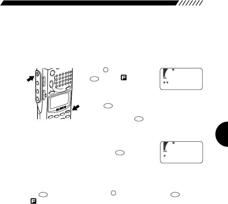
73
3.4.4 Setting memory scan radio
system (MODE SEL)
By setting a mode in the “MODE SEL” menu, the DJ-X2000 will selectively scan
the memory channels of the specified mode.
1Call up the MODE SEL screen.
Press the key, and then press
the key with shown on
the display.
The menu will appear. Point the
arrow at +MR using the dial or UP/DOWN key, and then
press the key.
The MR screen will appear. Point the arrow at +MODE
SEL and then press the key.
2Select the radio type you are scanning.
Using the dial or UP/DOWN key, point the arrow at the
radio type you are scanning. Press the key. The
radio type can be selected from ALL, AM, NFM, WFM,
USB, LSB, and CW. If ALL is selected, all the channels
will be scanned regardless of the radio type (the initial setting is ALL).
The display will return to the MR screen. Point the arrow at END and then press
the key (Alternatively, press the key, and then press the key with
appearing on the display).
ENT
TF
F
ENT
TF
ENT
TF
ENT
TF
ENT
TF
HELP
SET
F
MODE
AUTO MW
MIC
A-B S
M NAME
STEPATTSET
POWER
PMS
VFOMR MW
A B
SET
KL
3
2
1
RF C
HELP
MONI
F
SRCH
LAMP
SQL VOL
DOWN UP
MODE SE L
END
M
R
ALL
AM
M
ODE SE L
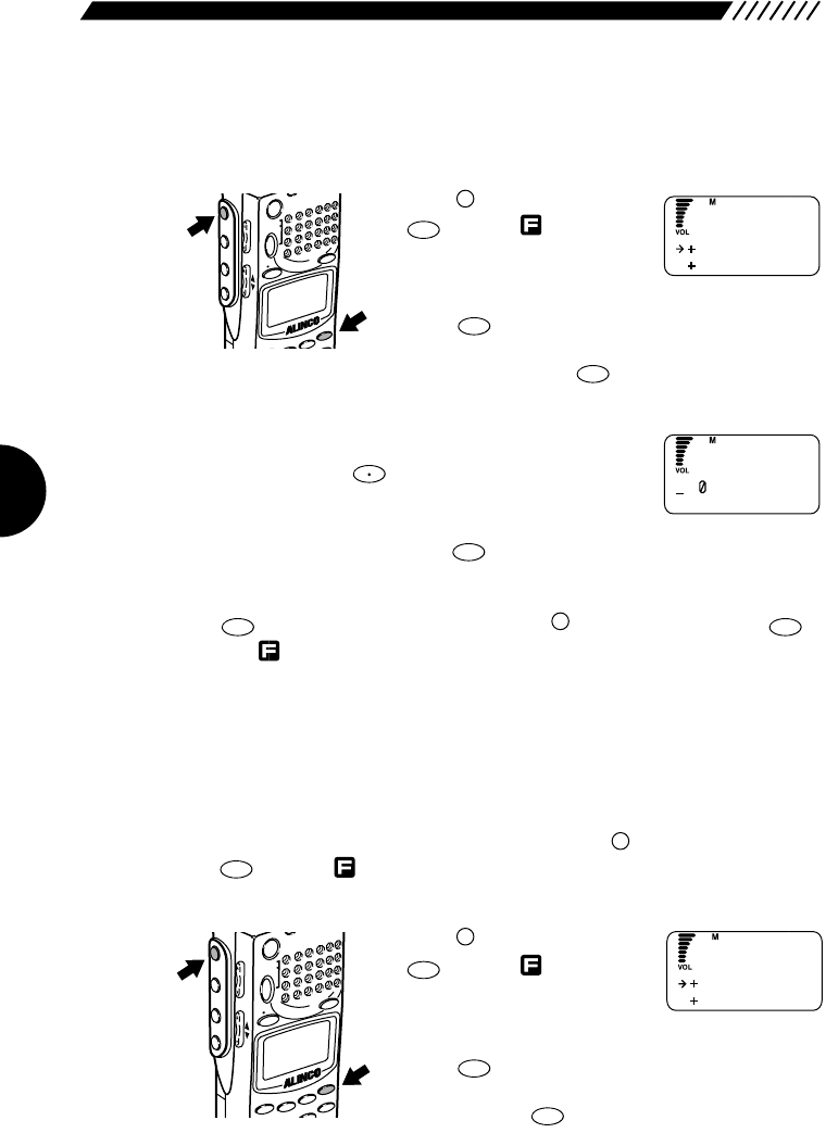
74
3.4.5 Using the BANK LINK function
This function lets you scan specific memory banks.
1Call up the MR LINK screen.
Press the key, and then press
the key with shown on
the display.
The menu will appear. Point the
arrow at +MR using the dial or UP/DOWN key, and then
press the key.
The MR screen will appear. Point the arrow at +MR
LINK and then press the key.
2Select the memory bank you want to use for scanning.
Using a numeric key, specify the bank number you want
to link. Pressing the key toggles from bank groups
A through E. To use all the memory banks for scanning,
select all the banks 0 through 9. After you have finished
specifying the bank(s), press the key.
The display will return to the MR screen. Point the arrow at END and then press
the key (Alternatively you may press the key, and then press the
key with appearing on the display).
3.4.6 Selecting memory channels for
scanning
Only the specified memory channels can be used for scanning. Up to 200
memory channels (20 programs x 10 banks) may be specified for scanning. To
perform scanning on the memory channels, press the key, and then press
the key with appearing on the display.
1Call up the PMR screen.
Press the key, and then press
the key with shown on
the display.
The menu will appear. Point the
arrow at +MR using the dial or UP/DOWN key, and then
press the key.
The MR screen will appear. Point the arrow at +PMR
and then press the key.
ENT
TF
ENT
TF
HELP
SET
F
MODE
AUTO MW
MIC
A-B S
M NAME
STEPATTSET
POWER
PMS
VFOMR MW
A B
SET
KL
3
2
1
RF C
HELP
MONI
F
SRCH
LAMP
SQL VOL
DOWN UP
SCN
A~B S
F
ENT
TF
F
ENT
TF
ENT
TF
F TUNE
ENT
TF
ENT
TF
HELP
SET
F
MO
DE
M N
AME
STEPATTSET
POWER
PMS
VFO MR MW
A B
SET
3
HELP
MONI
F
SRCH
LAMP
SQL VOL
DOWN UP
MR L I NK
MODE SE L
M
R
M
A1
---
5
----
B
----------
RBankLink
P
M
R
M
RLINK
M
R
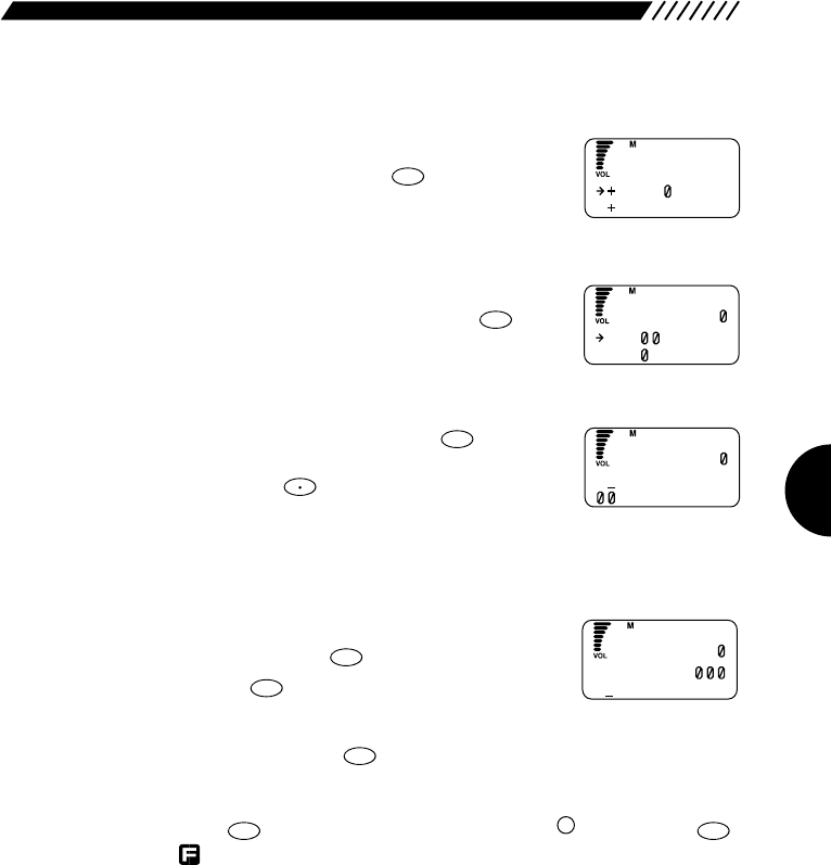
75
2Select the program bank on which you want to set a memory channel
for scanning.
Using the dial or UP/DOWN key, point the arrow at the
program you want to set. Press the key.
3Select the program number you want to assign to a memory channel.
Using the dial or UP/DOWN key, point the arrow at the
program number you want to select. Press the key.
4Select a memory bank.
Select a memory bank and then press the key.
Using the dial or a numeric key, specify a memory bank
number (Pressing the key toggles from bank groups
A through E). Move the arrow back to the position
pointing at the channel by pressing the DOWN key.
5Select a memory channel.
Using the dial or a numeric key, specify a memory
channel number. Press the key (To cancel the
setting, press the key).
Repeat the above steps 2 through 5 to register all the channels on which you are
scanning, and then press the key.
The display will return to the PMR BANK screen. Point the arrow at END and
then press the key (Alternatively you may press the key, and then
key with shown on the display).
ENT
TF
F
ENT
TF
ENT
TF
CLR
SKIP
ENT
TF
F TUNE
ENT
TF
ENT
TF
ENT
TF
BANK
BANK1
P
M
R
P
PG
-----
PG 1
-----
M
RBANK
P
A2
----
.
----
--------
M
R
M
E
MO
RY
P
A2 84 . 5
12 ABC
M
R
M
E
MO
RY
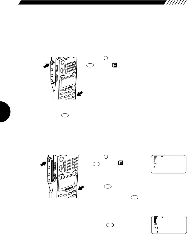
76
3.4.7 Scanning the memory channels
selected in the PMR screen
This function is used to scan only the memory channel selected on the PMR
screen (See “3.4.6 Selecting memory channels for scanning” (page 75)).
• Scanning only the memory channels selected on the PMR screen.
Press the key in the MR mode, and then press the
key with appearing on the display. Only the
channels selected on the PMR screen will be scanned.
The scanning direction can be changed using the dial or
UP/DOWN key.
• Stopping the scanning
Press the key again. The scanning will stop.
3.4.8 Copying memory banks
This function copies channels from one memory bank to another.
1Call up the MR EDIT screen.
Press the key, and then press
the key with shown on the
display.
The menu will appear. Point the
arrow at +MR using the dial or UP/DOWN key, and then
press the key.
The MR screen will appear. Point the arrow at +MR
EDIT and then press the key.
2Call up the COPY BANK screen.
Point the arrow at +COPY BANK using the dial or
UP/DOWN key, and then press the key.
ENT
TF
ENT
TF
ENT
TF
HELP
SET
F
MODE
AUTO MW
MIC
A-B S
M NAME
STEPATTSET
POWER
PMS
VFOMR MW
A B
SET
KL
3
2
1
RF C
HELP
MONI
F
SRCH
LAMP
SQL VOL
DOWN UP
SCN
A~B S
SCN
A~B S
F
MODE
AUTO MW
MIC
SCRTPR
IO CTCSSA-B S
M NAME
T
F
STEPATT
SET
POWER RX/ST
PMS
VFOMR MW
A B
SET
KL
3
6
9
5
2
1
4
SCN
RF C
HELP
MONI
F
SRCH
LAMP
SQL VOL
DOWN UP
COPY CH
MOV E CH
MR ED I T
COPY BANK
MOV E BANK
MR ED I T
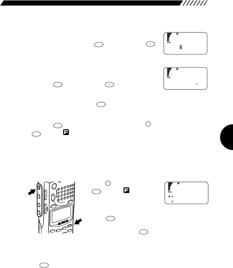
77
3Select a source memory bank.
Using the dial or a numeric key, select the bank number
you want to copy. Press the key (Pressing the
key toggles from bank groups A through E).
4Select a destination memory bank.
Using the dial or a numeric key, select the bank number
to which you want to copy the source memory bank.
Press the key (Pressing the key toggles from
bank groups A through E).
To retry the setting, press the key.
The display will return to the MR EDIT screen. Point the arrow at END and then
press the key (Alternatively you may press the key, and then press the
key with appearing on the display).
3.4.9 Copying memory channels
This function copies the contents of one memory channel to another.
1Call up the MR EDIT menu.
Press the key, and then press
the key with shown on
the display.
The menu will appear. Point the
arrow at +MR using the dial or UP/DOWN key, and then
press the key.
The MR screen will appear. Point the arrow at +MR
EDIT and then press the key.
2Call up the COPY CH screen.
Point the arrow at +COPY CH using the dial or UP/DOWN key, and then press
the key.
ENT
TF
ENT
TF
ENT
TF
HELP
SET
F
MODE
AUTO MW
MIC
A-B S
M NAME
STEPATTSET
POWER
PMS
VFOMR MW
A B
SET
KL
3
2
1
RF C
HELP
MONI
F
SRCH
LAMP
SQL VOL
DOWN UP
ENT
TF
F
ENT
TF
CLR
SKIP
F TUNE
ENT
TF
F TUNE
ENT
TF
CA=
--
OPY BANK
CA1 = B2
OPY BANK
COPY CH
MOV E CH
MR ED I T
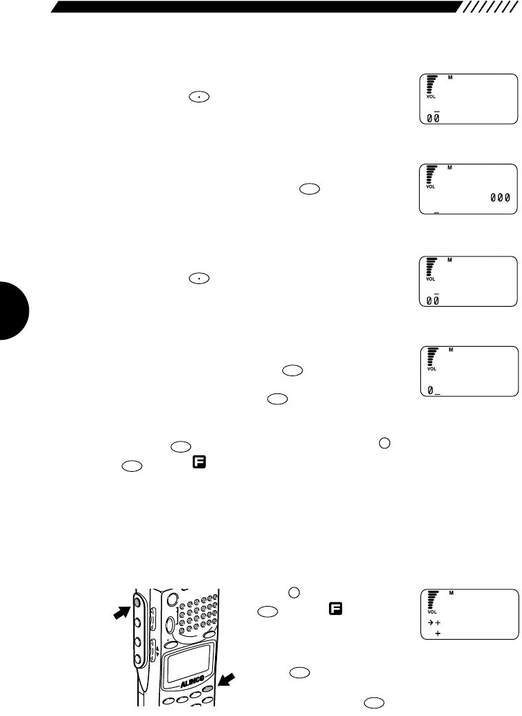
78
3Select the bank that includes the memory channel to be copied.
Select the bank number using the dial or a numeric key
(Pressing the key toggles from bank groups A
through E). Move the arrow to the position pointing at the
channel by pressing the DOWN key.
4Select the memory channel you are copying.
Using the dial or a numeric key, select the channel
number you are copying. Press the key.
5Select the bank that includes the destination memory channel.
Using the dial or a numeric key, select the bank number
(Pressing the key toggles from bank groups A
through E). Move the arrow to the position pointing at the
channel by pressing the DOWN key.
6Select the destination memory channel.
Select the destination channel number using the dial or a
numeric key, and then press the key.
To retry the setting, press the key.
The display will return to the MR EDIT screen. Point the arrow at END and then
press the key (Alternatively you may press the key, and then press the
key with appearing on the display).
3.4.10 Moving a memory bank
Any channel assigned to a memory bank can be moved to another memory
bank.
1Call up the MR EDIT screen.
Press the key, and then press
the key with shown on
the display.
The menu will appear. Point the
arrow at +MR using the dial or UP/DOWN key, and then
press the key.
The MR screen will appear. Point the arrow at +MR
EDIT and then press the key.
ENT
TF
ENT
TF
HELP
SET
F
MODE
AUTO MW
MIC
A-B S
M NAME
STEPATTSET
POWER
PMS
VFOMR MW
A B
SET
KL
3
2
1
RF C
HELP
MONI
F
SRCH
LAMP
SQL VOL
DOWN UP
ENT
TF
F
ENT
TF
CLR
SKIP
ENT
TF
F TUNE
ENT
TF
F TUNE
C
A2
----
.
----
--------
OPY FROM
C
A2 84 . 5
12 ABC
OPY FROM
C
B3
----
.
----
--------
OPY TO
C
B3
----
.
----
5
--------
OPY TO
COPY CH
MOV E CH
MR ED I T
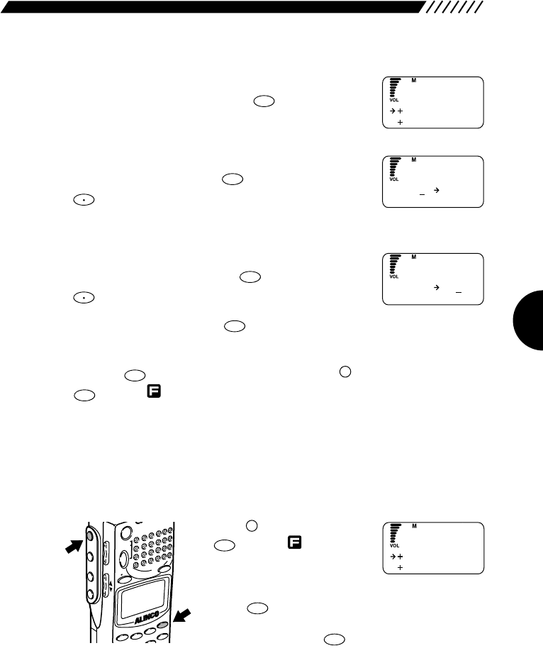
79
2Call up the MOVE BANK screen.
Point the arrow at +MOVE BANK using the dial or
UP/DOWN key, and then press the key.
3Select the memory bank you want to move.
Using the dial or a numeric key, select the memory bank
you want to move. Press the key (Pressing the
key toggles from bank groups A through E).
4Select the destination memory bank.
Select the destination bank number using the dial or a
numeric key, and then press the key (Pressing the
key toggles from bank groups A through E).
To retry the setting, press the key.
The display will return to the MR EDIT screen. Point the arrow at END and then
press the key (Alternatively you may press the key, and then press the
key with appearing on the display).
3.4.11 Moving a memory channel
This function is used to move the frequency and name assigned to a memory
channel to another memory channel.
1Call up the MR EDIT menu.
Press the key, and then press
the key with shown on
the display.
The menu will appear. Point the
arrow at +MR using the dial or UP/DOWN key, and then
press the key.
The MR screen will appear. Point the arrow at +MR
EDIT and then press the key.
ENT
TF
ENT
TF
HELP
SET
F
MODE
AUTO MW
MIC
A-B S
M NAME
STEPATTSET
POWER
PMS
VFOMR MW
A B
SET
KL
3
2
1
RF C
HELP
MONI
F
SRCH
LAMP
SQL VOL
DOWN UP
ENT
TF
F
ENT
TF
CLR
SKIP
F TUNE
ENT
TF
F TUNE
ENT
TF
ENT
TF
MO
VE BANK
DEL BANK
M
REDIT
M
A1
--
O
VE BANK
M
A1 B2
O
VE BANK
COPY CH
MOV E CH
MR ED I T
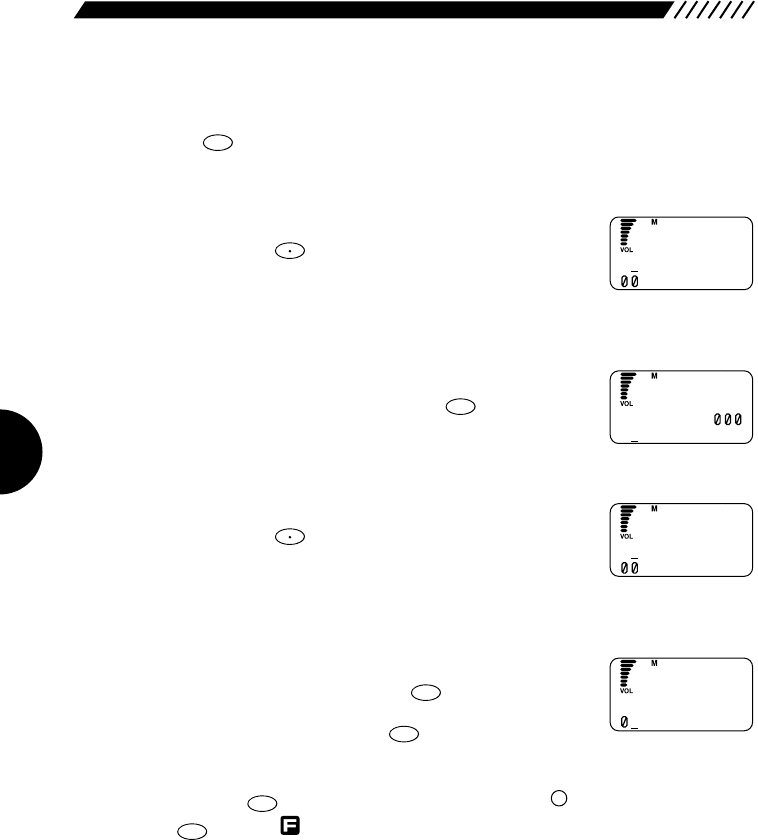
80
2Call up the MOVE CH screen.
Point the arrow at +MOVE CH using the dial or UP/DOWN key, and then press
the key.
3Select the bank that includes the memory channel you want to move.
Select the bank number using the dial or a numeric key
(Pressing the key toggles from bank groups A
through E). Move the arrow to the position pointing at the
channel by pressing the DOWN key.
4Select the memory channel you want to move.
Using the dial or a numeric key, select the channel
number you want to move. Press the key.
5Select the bank that includes the destination memory channel.
Select the bank number using the dial or a numeric key
(Pressing the key toggles from bank groups A
through E). Move the arrow to the position pointing at the
channel by pressing the DOWN key.
6Select the destination memory channel.
Select the destination channel number using the dial or a
numeric key, and then press the key.
To retry the setting, press the key.
The display will return to the MR EDIT screen. Point the arrow at END and then
press the key (Alternatively you may press the key, and then press the
key with appearing on the display).
ENT
TF
F
ENT
TF
CLR
SKIP
ENT
TF
F TUNE
ENT
TF
F TUNE
ENT
TF
M
A2
----
.
----
--------
OVE FROM
M
A2 84 . 5
12 ABC
OVE FROM
M
B3
----
.
----
--------
OVE TO
M
B3
----
.
----
5
--------
OVE TO
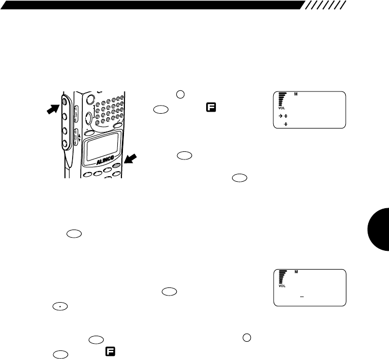
81
3.4.12 Deleting memory banks
This function deletes entire memory banks.
1Call up the MR EDIT screen.
Press the key, and then press
the key with shown on
the display.
The menu will appear. Point the
arrow at +MR using the dial or UP/DOWN key, and then
press the key.
The MR screen will appear. Point the arrow at +MR
EDIT and then press the key.
2Call up the DEL BANK screen.
Point the arrow at +DEL BANK using the dial or UP/DOWN key, and then press
the key.
3Select the memory bank you want to delete.
Using the dial or a numeric key, select the bank number
you want to delete. Press the key (Pressing the
key toggles from bank groups A through E).
The display will return to the MR EDIT screen. Point the arrow at END and then
press the key (Alternatively you may press the key, and then press the
key with appearing on the display).
ENT
TF
F
ENT
TF
F TUNE
ENT
TF
ENT
TF
ENT
TF
ENT
TF
HELP
SET
F
MODE
AUTO MW
MIC
A-B S
M NAME
STEPATTSET
POWER
PMS
VFOMR MW
A B
SET
KL
3
2
1
RF C
HELP
MONI
F
SRCH
LAMP
SQL VOL
DOWN UP
COPY CH
MOV E CH
MR ED I T
DA3
ELETE BANK
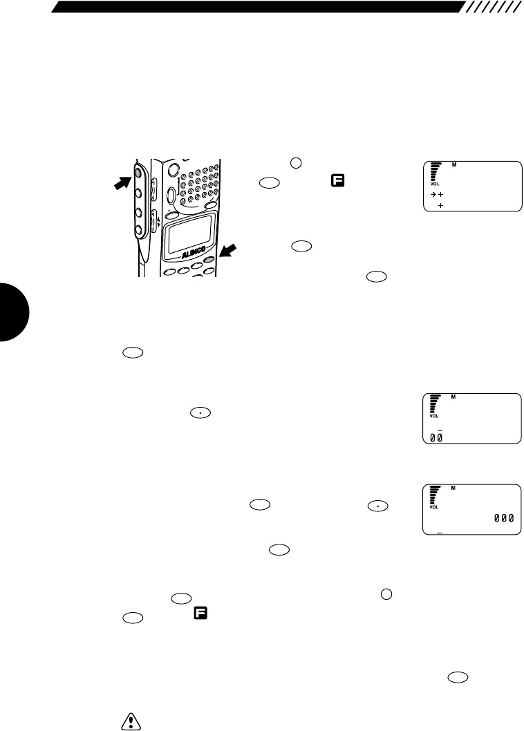
82
3.4.13 Deleting and restoring memory
channels
This function is used to delete and restore the frequency and name assigned to
a memory channel.
1Call up the MR EDIT screen.
Press the key, and then press
the key with shown on
the display.
The menu will appear. Point the
arrow at +MR using the dial or UP/DOWN key, and then
press the key.
The MR screen will appear. Point the arrow at +MR
EDIT and then press the key.
2Call up the DEL CH screen.
Point the arrow at +DEL CH using the dial or UP/DOWN key, and then press the
key.
3Select the bank that includes the memory channel you want to delete.
Select the bank number using the dial or a numeric key
(Pressing the key toggles from bank groups A
through E). Move the arrow to the position pointing at the
channel by pressing the DOWN key.
4Select the memory channel you want to delete.
Using the dial or a numeric key, select the channel you
want to delete. Press the key (Pressing the
key toggles from bank groups A through E).
To retry the setting, press the key.
The display will return to the MR EDIT screen. Point the arrow at END and then
press the key (Alternatively you may press the key, and then press the
key with appearing on the display).
• Restoring the deleted memory channel
The memory channel you have deleted can be restored. As in the above steps,
call up the channel number you have deleted, and then press the key. The
previously stored channel will be restored.
Note: If any other frequency is already assigned to the once deleted channel, the
previous channel data cannot be restored.
ENT
TF
ENT
TF
F
ENT
TF
CLR
SKIP
F TUNE
ENT
TF
F TUNE
ENT
TF
ENT
TF
ENT
TF
HELP
SET
F
MODE
AUTO MW
MIC
A-B S
M NAME
STEPATTSET
POWER
PMS
VFOMR MW
A B
SET
KL
3
2
1
RF C
HELP
MONI
F
SRCH
LAMP
SQL VOL
DOWN UP
COPY CH
MOV E CH
MR ED I T
D
A2
----
.
----
--------
EL
D
A2 84 . 5
12 ABC
EL
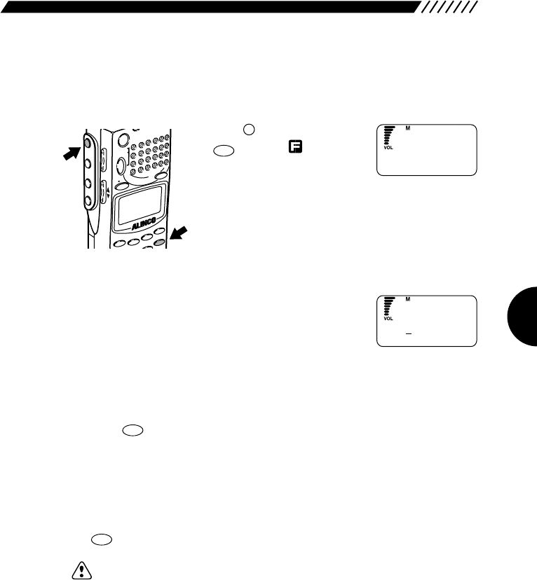
83
3.4.14 Searching for a memory tag
This function is used to search for a stored memory channel using its name.
1Call up the MR NAME SRC screen.
Press the key, and then press
the key with appearing
on the display.
2Enter the characters you want to search for.
Select each character by turning the dial, and then
establish it by pressing the DOWN key. The established
character can be canceled by pressing the UP key. Even
if you enter the first few characters, the appropriate
channel can be searched for. At least 1 character should be entered.
3Start the search.
Press the key. The search will start.
After the search has been finished, the appropriate channel appears on the
display. If more than 1 channel are found, “→” appears on the right end of the
display indicating that more than 1 channel have been found.
4Select a channel.
Using the dial or UP/DOWN key, select the channel you want to receive. Press
the key.
Note: If many memory channels are stored, it will take longer time for the search.
ENT
TF
ENT
TF
RFC
M NAME
F
MODE
AUTO MW
MIC
A-B S
M NAME
STEPATTSET
POWER
PMS
VFOMR MW
A B
SET
KL
3
2
1
RF C
HELP
MONI
F
SRCH
LAMP
SQL VOL
DOWN UP
M
ABCDEFGH I JK
R
NAME SRC
M
ABCDEFGH I JK
ABC
R
NAME SRC

84
4. Appendix
4.1 Specifications
Range of
received frequencies
Received radio type
Memory channel
Search path memory
Priority channel
Memory banks
1-bank channel
Band search
Antenna connector
Frequency steps
Receiving sensitivity
※
Excluding the frequency band
for electric communication
business use
※
The typical sensitivity values
are shown here.
0.1MHz∼2149.999950MHz
WFM, NFM, AM, USB, LSB, CW
2,000 channel
1,000channel
1channel (freely selectable from 2,000 channels)
50
40
20
BNC,50Ω
AUTO STEP, 50Hz, 100Hz, 200Hz, 500Hz, 1kHz, 2kHz, 5kHz,
6.25kHz, 8.33kHz, 9kHz, 10kHz, 12.5kHz, 15kHz, 20kHz, 25kHz,
30kHz, 50kHz, 100kHz, 125kHz, 150kHz, 200kHz, 250kHz,
500kHz, USER STEP (optional)
(
Only the digits of 1 MHz, 10 MHz, and 100 MHz can be changed.
)
0.1MHz∼5MHz AM 1.5μV (10dB S/N)
SSB/CW 0.6μV (10dB S/N)
5MHz∼900MHz
AM 1.0μV (10dB S/N)
SSB/CW 0.5μV (10dB S/N)
NFM 0.5μV (12dB SINAD)
WFM 2.0μV (12dB SINAD
when stereo signal are received)
900MHz∼2150MHz SSB/CW 1μV (10dB S/N)
NFM 2μV (12dB SINAD)
WFM 4μV (12dB SINAD)
Approx. 200 g
57×150×27.5mm
14∼50F
4.8V DC (Ni-Cd), 7.2V DC (Ni-Cd), 6V DC
(AA battery)
10∼16V DC
min.100 mW, 10% THD
At rated output: Approx. 150 mA (when 6 V power source is used)
At standby: Approx. 100 mA
In BS mode: Approx. 50 mA
Weight
External dimensions
Operating temperature
Power source
External power source
Rated output
Current consumption
Note: The North American version cannot be used to receive any frequency for cellular phones.
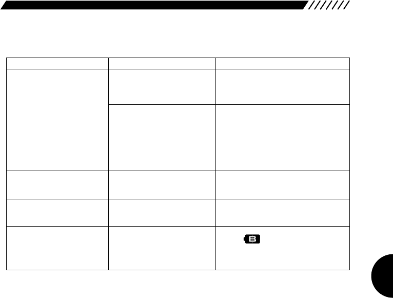
85
4.2 Troubleshooting
4.3 Optional items
The optional items available for the DJ-X2000 are listed below:
EBP-33N NiCd battery pack (4.8V 650mA)
EBP-34N NiCd battery pack (4.8V 1200mA)
EBP-35N NiCd battery pack (7.2V 900mA)
EBP-37N NiCd battery pack (4.8V 700mA)
EDC-36 Cigarette lighter cable with active filter
EDC-59 Rapid recharger
EME-6 Earphone
ESC-28 Soft case (Short size)
ESC-29 Soft case (Standard size)
ESC-30 Soft case (Long size)
EBC-6 Mobile bracket
DM-305MV
External DC power source
EDC-75 AC adapter-
EDC-37 DC cable for station use
Trouble Cause Remedial action
No sound is heard from
the speaker.
No signal can be
received.
The settings for
frequencies, etc. cannot
be performed.
The warning beep is
emitted or the sound is
distorted.
The display turns OFF.
The volume level is too
low.
The squelch level is too
high.
The antenna is not
properly set.
The key locking function
is active.
The battery has run out.
Press the VOL key on the left side of the
DJ-X2000, and then turn up the volume (see
page 20).
Press the SQL key on the left side of the
DJ-X2000, press the DOWN key to
decrease the level until any noise can be
heard, and then increase the level until
the noise is no longer heard (see page
21).
Properly attach the antenna (see
page 13).
Cancel the key locking function
(see page 28).
When appears on the display,
replace the battery.
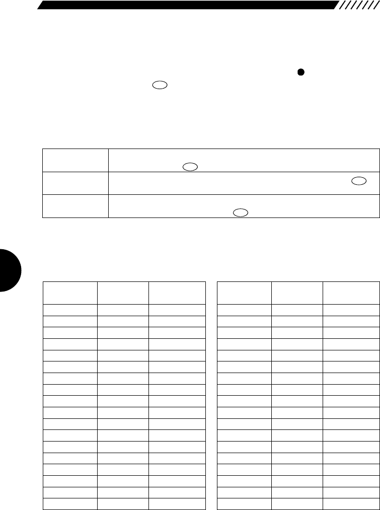
86
4.4 List of Help menu items
The list of Help menu items is given below. For the items marked with in the column for
"Function involved", when the key is pressed, the currently
displayed function or setting is executed.
For the operation procedure for the Help menu, see "2.15 Help menu" (page 32).
Organization of Help menu
Keys
ENT
TF
Describes how to use the Help information. Point the arrow at HELP
and then press the key.
Describes each key. Point the arrow at +KEY and then press the
key.
Describes the operation procedure for each function. Point the arrow at
+FUNCTION and then press the key.
Help
Keys
Function
ENT
TF
ENT
TF
ENT
TF
Operational
explanation available
●
●
●
●
●
●
●
●
●
●
●
●
●
●
●
●
●
●
Operational
explanation available
●
●
●
●
●
●
●
●
●
●
●
●
●
●
●
●
●
●
Menu
[SET]
[POWER]
[DIAL]
[VOL]
[SQL]
[F]
[MONI]
[F]&[MONI]
[LAMP]
[SRCH]
[F]&[SRCH]
[VFO]
[A=B]
[MR]
[MW]
[PMS]
[ENT]
[CLR]
Function involved Function involved
Menu
[SCN]
[RF C]
[.]
[MODE]
[STEP]
[ATT]
[MIC]
[
AUTO MW
]
[KL]
[M NAME]
[SCRT]
[PRIO]
[CTCSS]
[A∼B S]
[SKIP]
[REC]
[F TUNE]
[TF]

87
Functions
Menu Submenu
Function involved
Operational
explanation available
Inst
COPY A=B
COPY MR. CH
COPY PMS
Inst
COPY CH
DEL CH
COPY BANK
DEL BANK
MR LINK
MODE SEL
SCAN SKIP
SET CTCSS
M. TUNE
Inst
SCAN PASS
COPY
DEL
PMS LINK
AUTO MR WR
VFO
MR
A∼B S
MODE SCAN
PMR SCAN
VFO LINK
S_LEVEL
CTCSS SCAN
SCAN
SETUP
SCAN
MODE
SCAN MODE
BUSY Timer
RX Timer
SINGLE
INTERVAL
CONTINUE
SET
CH SCOPE
SCAN
PMS
MR
VFO
●
●
●
●
●
●
●
●
●
●
●
●
●
●
●
●
●
●
●
●
●
●
●
●
●
●
●
●
●
●
●
●
●
●
●
●
●
●
●
●
●
●
●
●
●
●
●
●
●
●
●
●
●
●
●
●
●
●
●
●

88
Function involved
Menu Submenu
Operational
explanation available
AUTO
MOMENTARY
ALTERNATE
Inst
Japanese
English
SET
Inst
TX CLONE
RX CLONE
MANUAL
REVERSE
SET
SYSTEM
ALL
A/B SQ SET
FLASH TUNE
RF CHECK
REC
TRANCEIVER
LAMP
TIMER
BEEP
TONE
STEREO
BELL
BATT SAVE
BATT VOLT
LANGUAGE
DIRECT WR
MESSAGE
CLONE
CTCSS SET
RESET
SPECIAL
●
●
●
●
●
●
●
●
●
●
●
●
●
●
●
●
●
●
●
●
●
●
●
●
●
●
●
●
●
●
●
●
●
●
●
●
●
●
●
●
●
●
●
●
●
●
●
●
CHECKER
CallWait
RX AF
MIC
SET

Copyright 2000, Alinco,Inc. Osaka Japan
Printed in Japan