USA Alo Branch DJ-X2000T Wide Range Scanning Receiver User Manual 2000448 FCC
USA Alinco Branch Wide Range Scanning Receiver 2000448 FCC
UserManual.wiki
>
USA Alo Branch
>
DJ X2000T User Manual
Manual
Navigation menu
Upload a User Manual
Namespaces
Wiki Guide
HTML
PDF
Info
Views
User Manual
Discussion / Help
Navigation
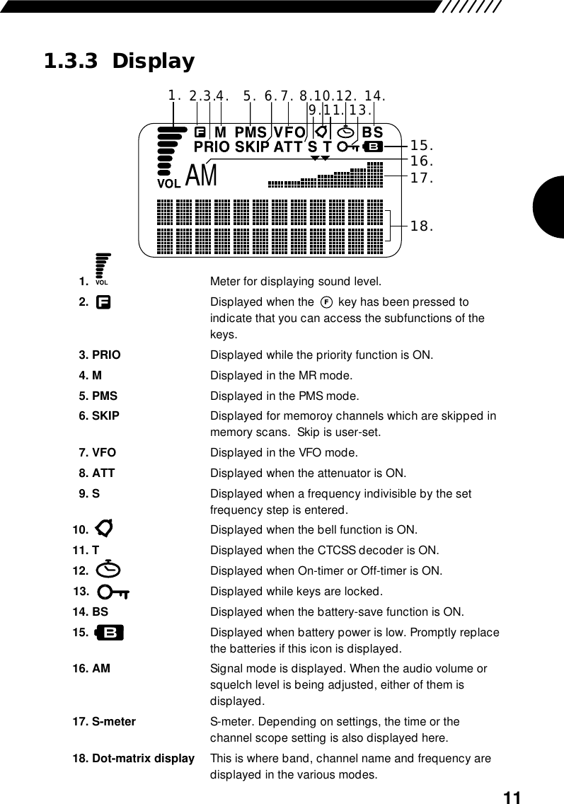
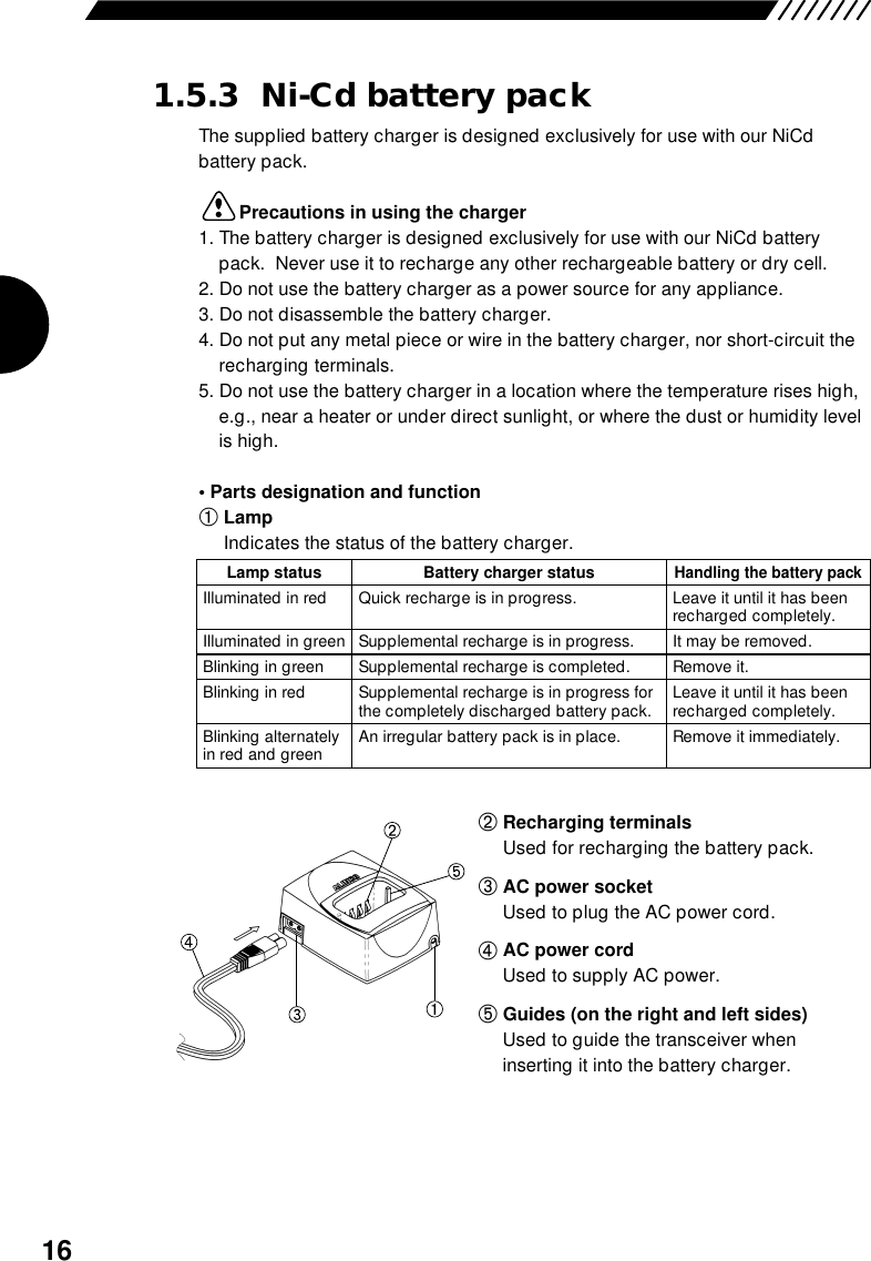
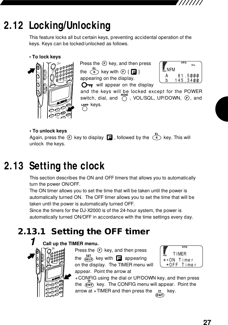
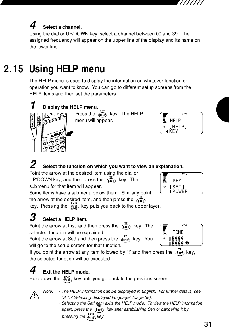
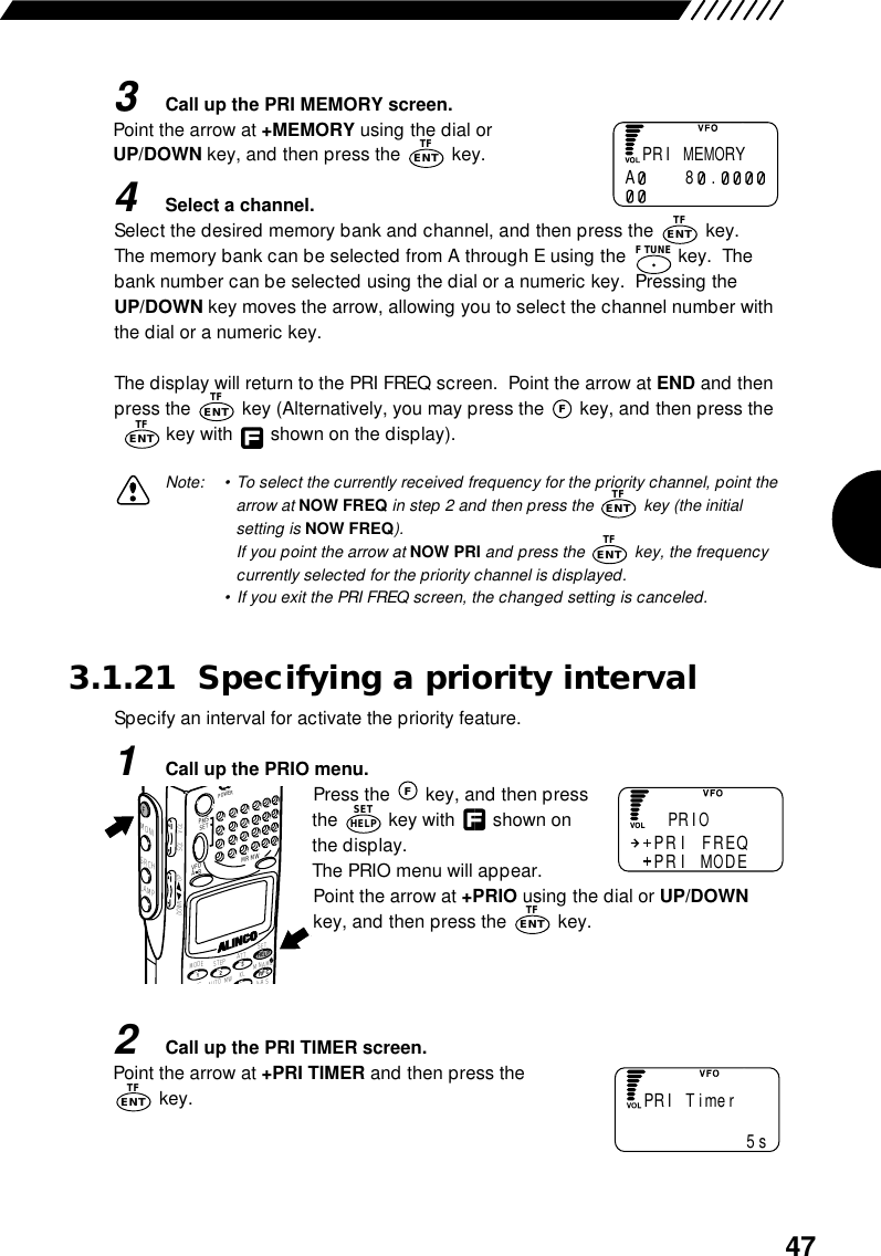
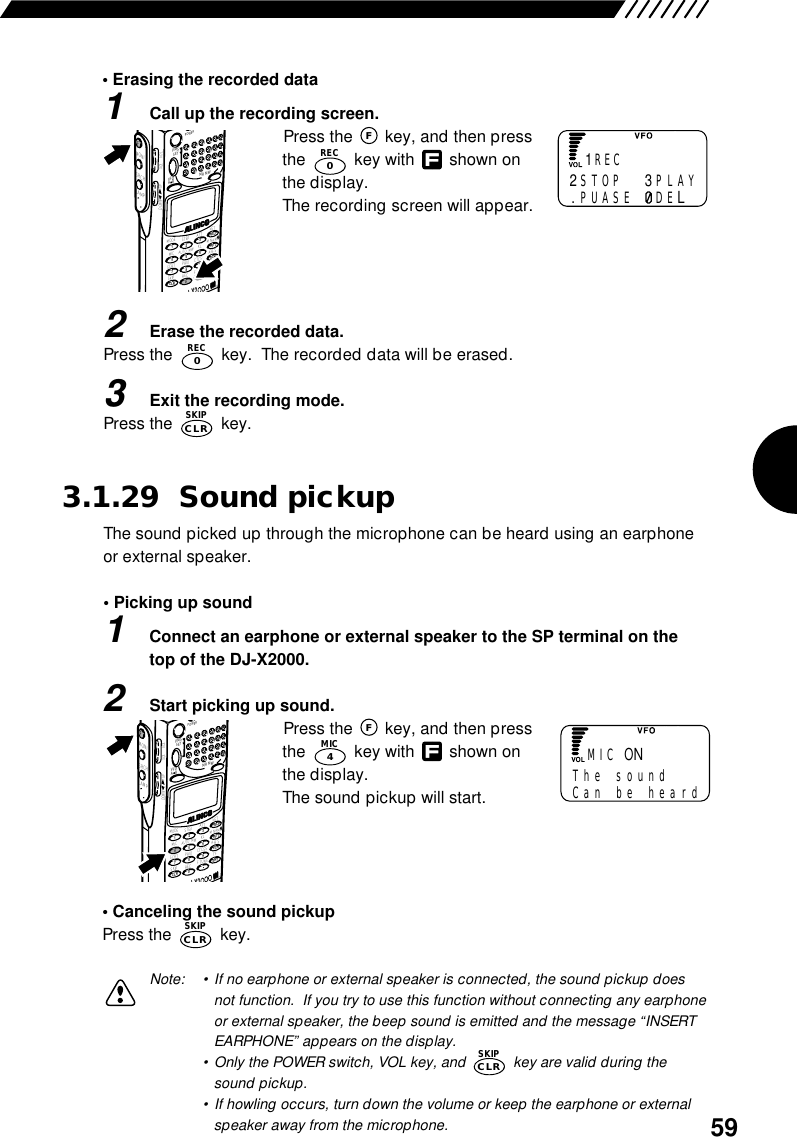
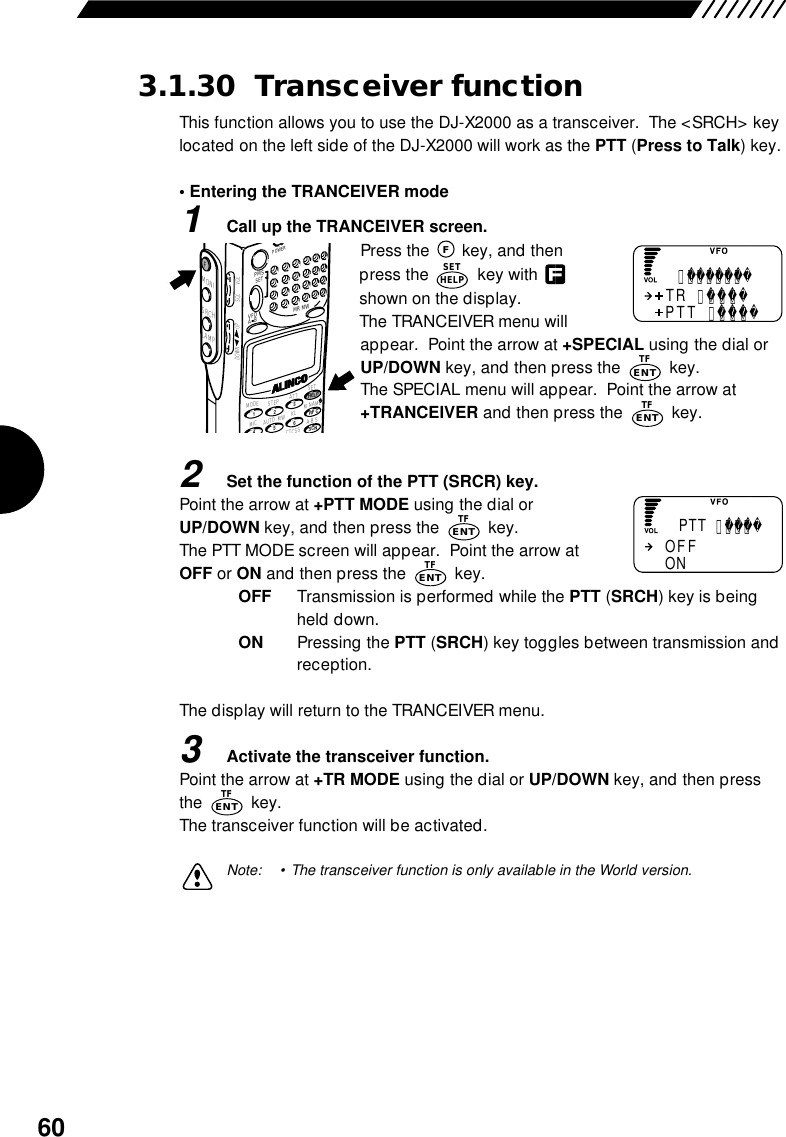
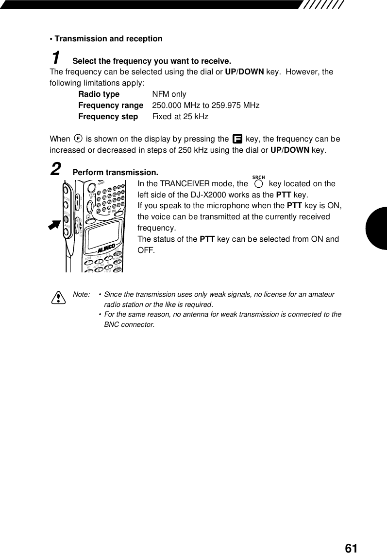
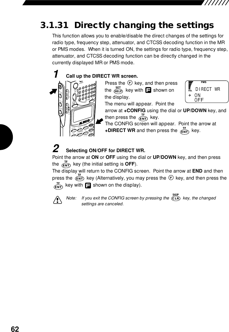
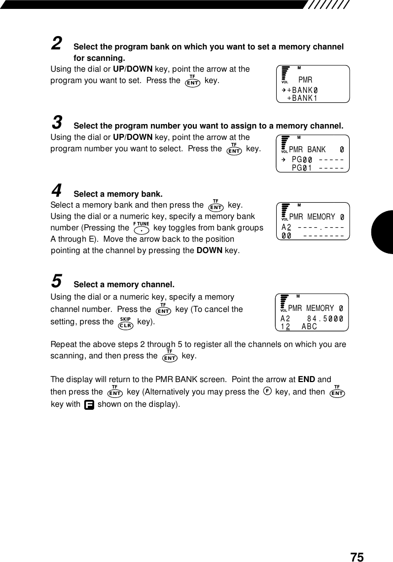
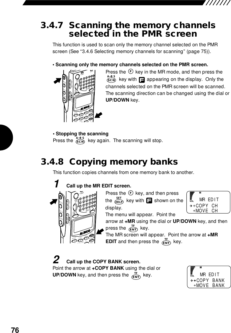
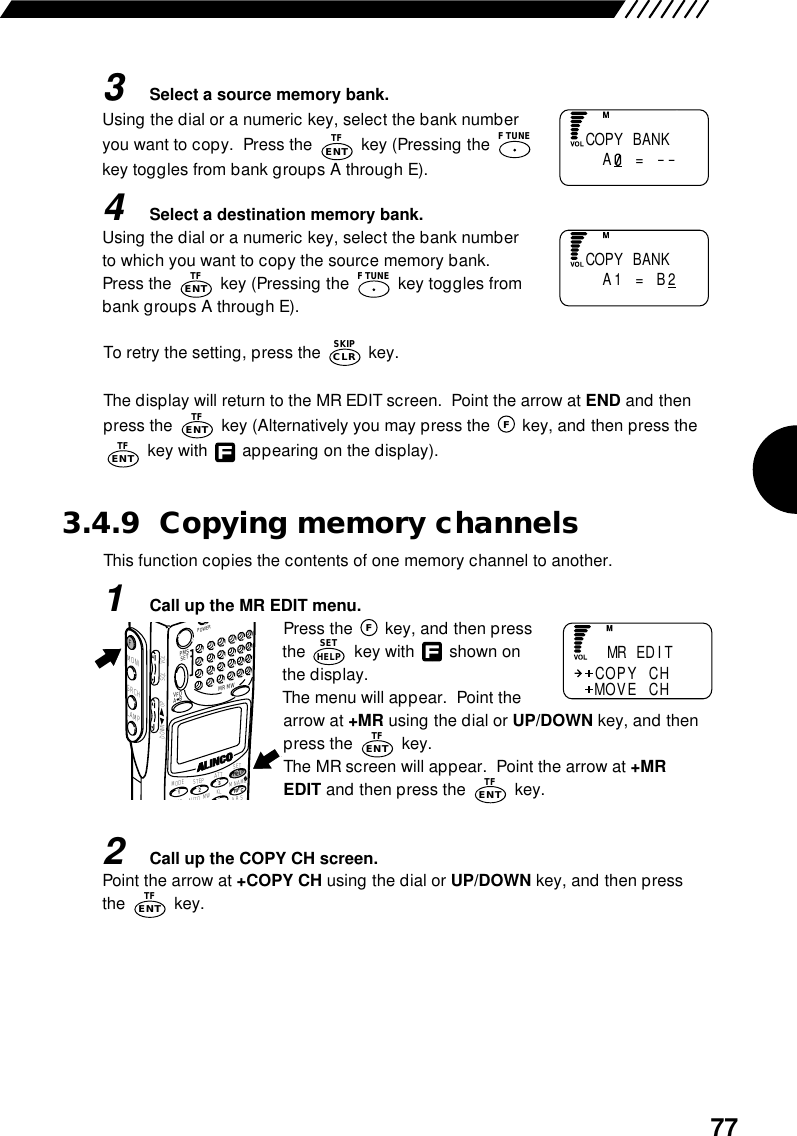
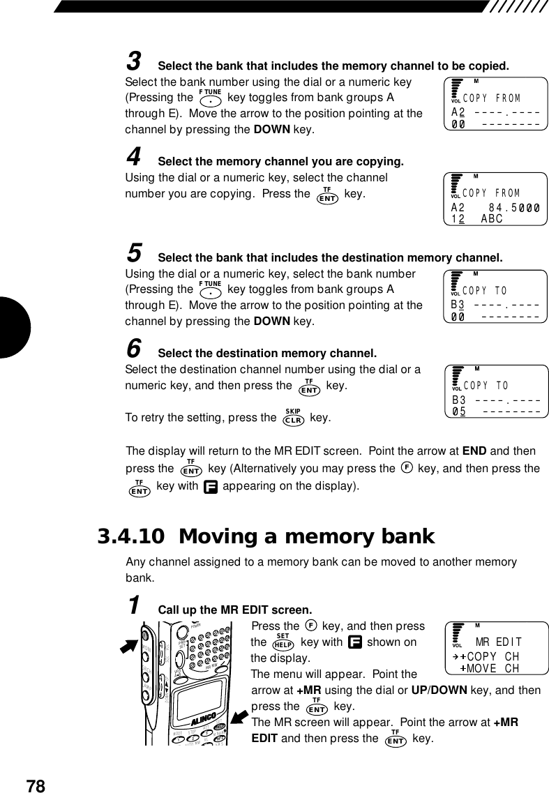
![864.4 List of Help menu itemsThe list of Help menu items is given below. For the items marked with in the column for"Function involved", when the key is pressed, the currentlydisplayed function or setting is executed.For the operation procedure for the Help menu, see "2.15 Help menu" (page 32).Organization of Help menuKeysENTTFDescribes how to use the Help information. Point the arrow at HELP and then press the key.Describes each key. Point the arrow at +KEY and then press the key.Describes the operation procedure for each function. Point the arrow at +FUNCTION and then press the key.HelpKeysFunctionENTTFENTTFENTTFOperational explanation available●●●●●●●●●●●●●●●●●●Operational explanation available●●●●●●●●●●●●●●●●●● Menu[SET] [POWER][DIAL][VOL][SQL][F][MONI][F]&[MONI][LAMP][SRCH][F]&[SRCH][VFO][A=B][MR][MW][PMS][ENT][CLR]Function involved Function involved Menu[SCN] [RF C] [.] [MODE] [STEP] [ATT] [MIC] [AUTO MW] [KL] [M NAME] [SCRT] [PRIO] [CTCSS] [A∼B S] [SKIP] [REC] [F TUNE] [TF]](https://usermanual.wiki/USA-Alo-Branch/DJ-X2000T/User-Guide-126046-Page-89.png)