UTC Fire and Security Americas RS3130 IR Network Camera User Manual
UTC FIRE & SECURITY AMERICAS CORPORATION, INC IR Network Camera
UserManual.wiki
>
UTC Fire and Security Americas
>
RS3130 User Manual
User Manual
Navigation menu
Upload a User Manual
Namespaces
Wiki Guide
HTML
PDF
Info
Views
User Manual
Discussion / Help
Navigation
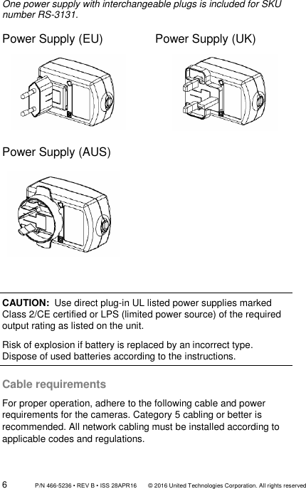
![P/N 466-5236 • REV B • ISS 28APR16 © 2016 United Technologies Corporation. All rights reserved 11 3. Loosen the screws with the tamper-resistant hex wrench (supplied) to remove the camera cover. 4. Mount the camera base to the converter pan or mounting surface, depending on the installation. 5. Use the supplied lens alignment tool to adjust the pan [±30°], tilt [0 to 80°], and rotation direction [0 to 360°]. Tilt Pan Adjusting Tool Rotation](https://usermanual.wiki/UTC-Fire-and-Security-Americas/RS3130/User-Guide-3040200-Page-11.png)