UTC Fire and Security Americas RS3130 IR Network Camera User Manual
UTC FIRE & SECURITY AMERICAS CORPORATION, INC IR Network Camera
User Manual

P/N 466-5236 • REV B • ISS 28APR16 © 2016 United Technologies Corporation. All rights reserved 1
UltraSync Wi Fi IP Camera
Installation Guide
2 P/N 466-5236 • REV B • ISS 28APR16 © 2016 United Technologies Corporation. All rights reserved
Contents
Installation environment ...........................................................3
Package contents ....................................................................4
Cable requirements .................................................................6
Camera description .................................................................7
Accessing the SD card ............................................................8
Wedge Camera .....................................................................9
Desktop Camera ...................................................................9
Mounting the Wedge Camera ................................................ 10
Mounting the Desktop Camera .............................................. 13
Quick Setup ........................................................................... 16
Setting up Ethernet/Wi Fi transmission .................................. 16
Wi Fi Signal Strength ............................................................. 17
Add Cameras to a Wi Fi Network ........................................... 18
Add Cameras to UltraSync .................................................... 19
Reboot Cameras ................................................................... 20
View Live Stream and Latest Clip .......................................... 20
Program Event Triggered camera clips .................................. 21
Change Default Camera Settings ........................................... 26
Alternatives for Adding Cameras............................................ 27
via Wi Fi (using Windows PC for setup) ............................... 27
via Ethernet (non-DHCP, using iOS Device for setup) .......... 27
via Ethernet (non-DHCP, using Windows PC for setup) ....... 28
Troubleshooting ..................................................................... 29
Specifications ........................................................................ 31
P/N 466-5236 • REV B • ISS 28APR16 © 2016 United Technologies Corporation. All rights reserved 3
Installation environment
When installing your product, consider these
factors:
• Electrical: Install electrical wiring carefully. It should be done by
qualified service personnel. Always use a proper PoE switch or
a 12 VDC UL listed Class 2 or CE certified power supply to
power the camera. Do not overload the power cord or adapter.
• Ventilation: Ensure that the location planned for the installation
of the camera is well ventilated.
• Temperature: Do not operate the camera beyond the specified
temperature, humidity or power source ratings. The operating
temperature of the camera is between -30 to +60°C (-22 to
140°F). Humidity is below 90%.
• Moisture: Do not expose the camera to rain or moisture, or try
to operate it in wet areas. Turn the power off immediately if the
camera is wet and ask a qualified service person for servicing.
Moisture can damage the camera and also create the danger of
electric shock.
• Servicing: Do not attempt to service this camera yourself. Any
attempt to dismantle or remove the covers from this product will
invalidate the warranty and may also result in serious injury.
Refer all servicing to qualified service personnel.
• Cleaning: Do not touch the sensor modules with fingers. If
cleaning is necessary, use a clean cloth with some ethanol and
wipe the camera gently. If the camera will not be used for an
extended period of time, put on the lens cap to protect the
sensors from dirt.
4 P/N 466-5236 • REV B • ISS 28APR16 © 2016 United Technologies Corporation. All rights reserved
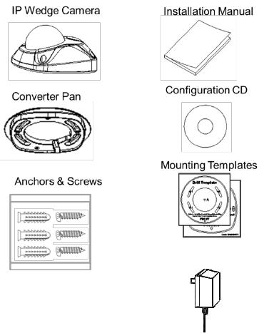
Package contents
Check the package and contents for visible damage. If any
components are damaged or missing, do not attempt to use the
unit; contact the supplier immediately. If the unit is returned, it must
be shipped back in its original packaging.
UltraSync Wi Fi IP Wedge Camera
Transformer
P/N 466-5236 • REV B • ISS 28APR16 © 2016 United Technologies Corporation. All rights reserved 5
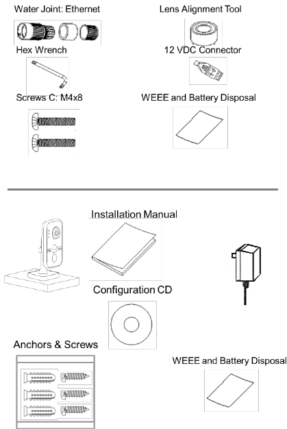
UltraSync Wi Fi IP Desktop Camera
Power Supply (US)
6 P/N 466-5236 • REV B • ISS 28APR16 © 2016 United Technologies Corporation. All rights reserved
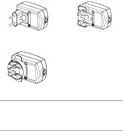
One power supply with interchangeable plugs is included for SKU
number RS-3131.
Power Supply (EU)
Power Supply (UK)
Power Supply (AUS)
CAUTION: Use direct plug-in UL listed power supplies marked
Class 2/CE certified or LPS (limited power source) of the required
output rating as listed on the unit.
Risk of explosion if battery is replaced by an incorrect type.
Dispose of used batteries according to the instructions.
Cable requirements
For proper operation, adhere to the following cable and power
requirements for the cameras. Category 5 cabling or better is
recommended. All network cabling must be installed according to
applicable codes and regulations.
P/N 466-5236 • REV B • ISS 28APR16 © 2016 United Technologies Corporation. All rights reserved 7
Camera description – Wedge Camera
9
2
1
6
8
7
3
5
4
10
1
1
1. Camera cover/housing
2. Lens
3. SD card
4. Ethernet RJ45 PoE port
5. Power supply
6. Base
7. Alarm and Audio port
8. Reset/WPS button
9. Converter pan
10. Antenna
11. Microphone
8 P/N 466-5236 • REV B • ISS 28APR16 © 2016 United Technologies Corporation. All rights reserved
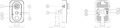
Camera description – Desktop Camera
1. Lens
2. Microphone
3. IR LED
4. PIR
5. Light sensor
6. SD card slot
7. Bracket stand
8. RJ45 network port
9. WPS/RET button
10. Alarm I/O
11. DC12V port
P/N 466-5236 • REV B • ISS 28APR16 © 2016 United Technologies Corporation. All rights reserved 9
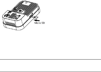
Accessing the SD card
Wedge Camera
An 8GB Micro SD card is pre-installed with the camera; (see item 3
in Camera Description, page 6).
Desktop Camera
An 8GB Micro SD card is pre-installed with the camera.
If desired, the Micro SD Card can be replaced with up to 64GB for
local storage as a backup in case, for example, the network fails.
Note: Video and log files stored on the Micro SD card can only be
accessed via the UltraSync App when validated with the UltraSync
Panel.
10 P/N 466-5236 • REV B • ISS 28APR16 © 2016 United Technologies Corporation. All rights reserved
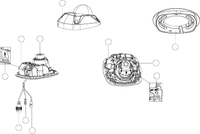
Mounting the Wedge Camera
To mount the wedge camera on a wall or ceiling:
1. Drill the holes for the mounting hardware in the mounting
surface using the supplied drill template. To route the cables
from the base of the camera, drill a cable access hole in the
mounting surface.
2. Mount the converter pan to the mounting surface (optional).
Note: If required, you can remove the tab (A) on the side of
the converter pan to pass the cables through.
A
P/N 466-5236 • REV B • ISS 28APR16 © 2016 United Technologies Corporation. All rights reserved 11
3. Loosen the screws with
the tamper-resistant hex
wrench (supplied) to
remove the camera cover.
4. Mount the camera base to
the converter pan or
mounting surface,
depending on the
installation.
5. Use the supplied lens
alignment tool to adjust
the pan [±30°], tilt
[0 to 80°], and rotation
direction [0 to 360°].
Tilt
Pan
Adjusting
Tool
Rotation
12 P/N 466-5236 • REV B • ISS 28APR16 © 2016 United Technologies Corporation. All rights reserved
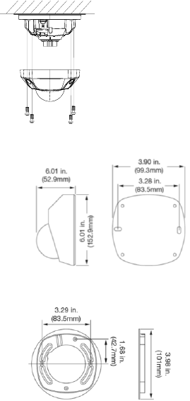
6. Re-attach the dome
cover to the camera.
Wedge Camera Dimensions
Wedge Camera Mounting Plate Dimensions
P/N 466-5236 • REV B • ISS 28APR16 © 2016 United Technologies Corporation. All rights reserved 13
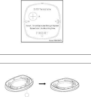
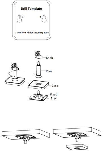
Mounting the Desktop Camera
1. Drill the screw holes
according to the drill
template.
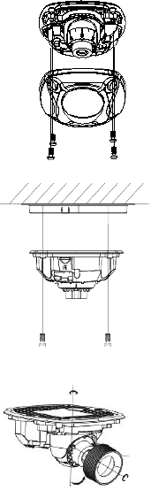
2. Disassemble the 3-
axis bracket. Hold
the base with one
hand, and rotate the
pole anticlockwise to
disassemble the
pole from the base.
3. Install the fixed tray to the ceiling with the supplied screws.
4. Install the base to the fixed plate.
14 P/N 466-5236 • REV B • ISS 28APR16 © 2016 United Technologies Corporation. All rights reserved
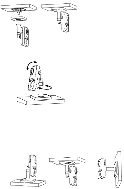
5. Install the camera to
the bracket.
6. Adjust surveillance
angle
7. Loosen the knob to adjust the panning position and tilting
position.
8. After adjusting the angle of the camera to the desired
position, fasten the knob.
Knob
90°
360°
P/N 466-5236 • REV B • ISS 28APR16 © 2016 United Technologies Corporation. All rights reserved 15
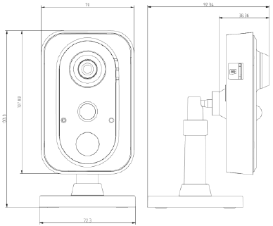
Desktop Camera Dimensions

16 P/N 466-5236 • REV B • ISS 28APR16 © 2016 United Technologies Corporation. All rights reserved
Quick Setup
Note: If the light source where the camera is installed experiences
rapid, wide variations in lighting, the camera may not operate as
intended.
To quickly put the camera into operation:
1. Prepare the mounting surface.
2 Mount the camera using the appropriate fasteners. See
“Mounting the Wedge Camera” on page 10 or “Mounting the
Desktop Camera” on page 13.
3. Connect the camera to the local network via Ethernet or Wi Fi.
4. Learn the camera into the UltraSync App using the “Scan for
New Cameras” button in Settings > Cameras
Setting up Ethernet/Wi Fi transmission
Wi Fi transmission distance
The Wi Fi transmission distance/range of the camera is
approximately 50 m (164 ft.) in open air applications.
Note: The transmission distance may vary due to the presence of
physical obstacles, such as trees, walls, elevators, fire doors,
furniture, etc. Avoid very solid walls and metallic objects in the
transmission path.
Other Wi Fi networks (for example Wi Fi, WiMAX) operating on
2.4 GHz and certain types of devices (e.g., microwave oven or
point-to-point Wi Fi transmission) can cause interference with your
network. The result would lead to a reduction in transmission
distance/range.
Note: It is highly recommended to use a dedicated router for all
UltraSync installations that include cameras.
• Removes concern of homeowners changing their Wi-Fi
Password, resulting in a call to update.
• Maintains privacy for the homeowner’s for Wi-Fi Network
Password.
• Reduces the risk of local communication issues between the
router, cameras and UltraSync Panels.

P/N 466-5236 • REV B • ISS 28APR16 © 2016 United Technologies Corporation. All rights reserved 17
Wi Fi Signal Strength
Wi Fi signal strength can be checked in the Network section of the
TruVision Browser. Use the scale below to measure if actions are
needed to improve performance.
85+ – Excellent:
No additional actions needed and default video resolutions settings
may be increased if desired.
75-85 – Very Good:
No additional actions needed to increase signal strength. It is not
recommended to increase video resolution settings.
65-75 – Good:
It is recommended to use a Wi Fi repeater or Powerline adapter to
increase signal strength. Alternatively, video resolutions settings
may be reduced to minimize poor video quality.
Below 65 – Poor:
It is not recommended to use the camera with a signal strength
below 65. Video streams will likely not work below this level.
A Wi Fi repeater or Powerline adapter should be used to increase
signal strength.
Devices Supported For Ad Hoc Installation
Apple iOS, PC – Windows XP, 7, 8
Devices NOT Supported For Ad Hoc Installation
Android, Windows Mobile, Blackberry
Below 65
Poor
65-75
Good
75-85 Very
Good
85+
Excellent

18 P/N 466-5236 • REV B • ISS 28APR16 © 2016 United Technologies Corporation. All rights reserved
Add Cameras to a Wi Fi Network
RECOMMENDED METHOD
(using temporary Ethernet connection for setup)
Note: It is highly recommended to use a dedicated router for all
UltraSync installations that include cameras.
• Removes concern of homeowners changing their Wi-Fi
Password, resulting in a call to update.
• Maintains privacy for the homeowner’s for Wi-Fi Network
Password.
• Reduces the risk of local communication issues between the
router, cameras and UltraSync Panels.
1. Apply power to the camera using the included transformer.
Note: Power up may take 1-2 minutes
2. Connect the camera to your router with an Ethernet cable.
3. Launch TruVision Device Manager.
Note: Use the included CD or download at www.interlogix.com/video
4. Verify that the camera is found in the main camera selection window.
5. Select the camera you would like to configure.
6. In the Password field, enter the default password of 1-2-3-4 and
press Save.
7. In the main camera selection window, select the camera you
would like to configure and double click the IPV4 Address to
launch TruVision IP Camera Configurator in a browser.
Note: You may also manually enter the camera’s IP Address in
your desired internet browser.
8. Enter the default Username and Password and select Login.
Note: A pop-up may appear instructing an immediate password
change. Select OK.
9. Select Configuration on the top menu.
10. Select Network on the left menu.
11. Select Wi Fi on the middle tab.
12. Select the desired Wi Fi network from the Wireless List.
13. Enter Wi Fi Network Passphrase in Key 1 Section.

P/N 466-5236 • REV B • ISS 28APR16 © 2016 United Technologies Corporation. All rights reserved 19
14. Click Save on the bottom of the screen.
Note: Do not hit Connect in the WPS Section.
15. Below the Key 1 box, verify that “Your Network” is now
showing connected.
16. Repeat steps for any additional cameras.
Note: Do not exit the TruVision Camera Configurator browser.
You are now connected to the network via Wi Fi!
Add Cameras to UltraSync
Ensure proper installation of camera hardware and adding cameras
to network before adding cameras to UltraSync.
Note: Make sure camera and UltraSync intrusion panel are on the
same local area network. Applications where the Intrusion panels
uses cellular only (no Wi Fi or Ethernet connection) are not
compatible with this camera.
Note: For detailed information on how to setup the UltraSync app,
add locations, and login as an installer, reference the intrusion
panel installation guide.
1. From your iOS or Android device, open the UltraSync App and
log in to the site as the installer.
2. Click More on the bottom of the Screen, then Settings.
3. Select Cameras under Settings.
4. Select Scan for New Cameras.
5. “Success!” message will pop-up after a few moments.
Note: "Success" message appears after a camera scan was
executed. This does not indicate cameras were added to the
system.
6. The IP Address and MAC Address should automatically
populate for all cameras on the network. Scroll through cameras
using the camera selection list to verify connected cameras.
7. Click Save.
Note: Camera may take up to 1-2 minutes to finalize association
with intrusion panel and show in cameras tab.
20 P/N 466-5236 • REV B • ISS 28APR16 © 2016 United Technologies Corporation. All rights reserved
Reboot Cameras
8. Reopen TruVision IP Camera Configurator (Browser)
9. Select System from the menu on the left.
10. Select Maintenance from the middle menu.
11. Select Reboot.
i) Select OK when asked if you want to reboot the unit.
ii) Note: Reboot may take 1-2 minutes.
12. Disconnect the Ethernet cable from the camera.
13. Go to the Cameras Tab in the UltraSync App to verify live
video.
Your Camera installation is now complete!
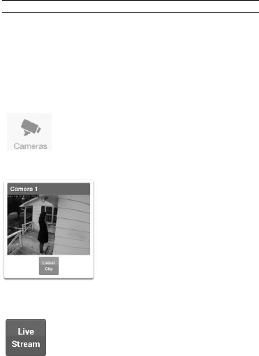
View Live Stream and Latest Clip
1. Click Cameras tab on bottom of the screen.
2. All available cameras will be shown.
3. Click Live Stream to view a live feed of a specific camera.
P/N 466-5236 • REV B • ISS 28APR16 © 2016 United Technologies Corporation. All rights reserved 21
4. Click Latest Clip to view the last recorded clip from a
specific camera.
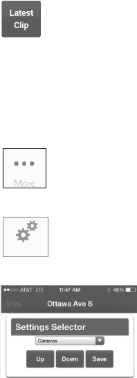
Program Event Triggered camera clips
Cameras can be programmed to automatically record when
selected events occur. This is achieved by creating a scene.
1. Click More on the bottom of the screen.
2. Click Settings.
3. Select Scenes under Settings Selector.
Settings
22 P/N 466-5236 • REV B • ISS 28APR16 © 2016 United Technologies Corporation. All rights reserved
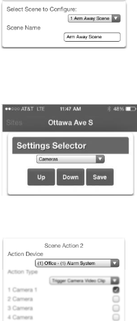
4. Select the Scene to Configure and type Scene Name.
5. Select the Scene Trigger.
6. Select Alarm System under Action Device.
7. Select Trigger Camera Video Clip under Action Type.
P/N 466-5236 • REV B • ISS 28APR16 © 2016 United Technologies Corporation. All rights reserved 23
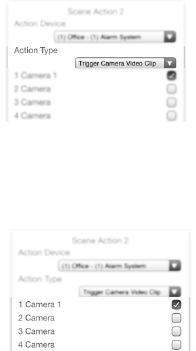
8. Select the Camera(s) which will record when the scene is
triggered.
9. Clips are recorded on the Micro SD card installed in the camera
and are linked to events in History.
See page 22 to see how to view event triggered clips.
24 P/N 466-5236 • REV B • ISS 28APR16 © 2016 United Technologies Corporation. All rights reserved
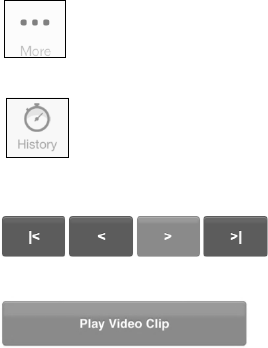
View Event Triggered clips in History
1. Click More tab on bottom of the screen.
2. Click History.
3. Find the Event you wish to view using Oldest, Prev, Next, and
Latest buttons.
4. Once you find the clip you wish to view, click Play Video Clip.
P/N 466-5236 • REV B • ISS 28APR16 © 2016 United Technologies Corporation. All rights reserved 25
Remove Camera from UltraSync (if needed)
1. Click the More tab on the bottom of the Screen.
2. Click Settings
3. Select Cameras under Settings Selector
4. Select the camera you with to remove.
5. Delete text in Camera Name, IP Address and MAC Address.
6. Click Save.
Note: To remove all cameras from UltraSync, go to Advanced
Settings and use SHORTCUT 910.22.
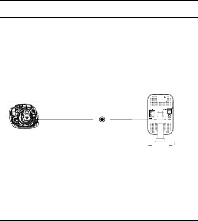
Reset Cameras to Factory Default (if needed)
If needed, the cameras can be reset to factory default.
Wedge Camera:
Remove the camera cover, remove power from camera, then press
and hold the RST/WPS button, apply power to camera and
continue holding RST/WPS button for 20 Seconds.
Desktop Camera:
1. Enter the Maintenance interface:
Configuration > Basic Configuration> System > Maintenance
Or Configuration > Advanced Configuration> System > Maintenance
2. Click Restore or Default to restore the default settings.
You can also use the RESET button on the desktop camera to
default the camera.
Note: After restoring the default settings, the IP address is also
restored to the default IP address.
RST/WPS

26 P/N 466-5236 • REV B • ISS 28APR16 © 2016 United Technologies Corporation. All rights reserved
Change Default Camera Settings
(Via TruVision Navigator)
1. From a computer or mobile device that is connected on the
same network as the camera, type in the IP address of the
camera into the device’s browser.
2. Login using default login
a. Login: admin
b. Password: 1234
3. Change settings as desired such as video quality, frame rate, pre
and post recording times.
4. For detailed instructions on using TruVision Navigator, go to
www.interlogix.com/video
Note: To find the IP address of a camera connected to UltraSync,
go to Settings > Cameras in the UltraSync App.
P/N 466-5236 • REV B • ISS 28APR16 © 2016 United Technologies Corporation. All rights reserved 27
Alternatives for Adding Cameras
via Wi Fi (using Windows PC for setup)
1. Power up the camera. (Boot up may take 1-2 minutes)
2. From your Windows PC, find and connect to your camera in the Wi Fi network list.
3. Go to Network and Sharing Center.
Control Panel > Network and Internet > Network and Sharing Center.
4. Click Change Adapter Settings on left.
5. Right click Wireless Network Connection and select Properties.
6. Click Internet Protocol Version 4 (TCP/IPv4) and click Properties.
7. Click “Use the following IP address”, enter the info below, and then click OK.
a) IP address: 192.168.2.71
b) Subnet mask: 255.255.255.0
8. Open Browser (Firefox, Chrome, IE8) and enter the camera’s IP Address into the
browser’s address bar.
a) Camera’s Default IP Address is 192.168.2.70.
9. TruVision Configurator will appear. Enter Credentials below.
a) User Name: admin
b) Password: 1-2-3-4
10. Click Configuration on the top menu.
11. Click Network on the left menu.
12. Click Wi Fi on the middle tab.
13. Select your network from the Wireless List.
14. Enter Wi Fi Network Passphrase in Key 1 Section.
15. Click Save on the bottom of the screen.
via Ethernet (non-DHCP, using iOS Device for setup)
1. Power up the camera. (Boot up may take 1-2 minutes)
2. From your iOS device, go to Settings, then Wi Fi.
3. Find and select your camera (Listed under Devices)
4. Once connected, hit the info circle on the right
5. Under IP Address, hit Static and enter the info below.
a) IP Address: 192.168.2.71
b) Subnet Mask: 255.255.255.0
6. Open Mobile Browser. (Safari)
7. Enter the camera’s default IP Address into the address bar.
a) 192.168.2.70
8. TruVision Configurator will appear. Enter Credentials below.
a) User Name: admin
b) Password: 1-2-3-4
9. Click Configuration on the top menu.
10. Click Network on the left menu.
11. Change LAN settings to desired configuration.
a) Change the IPv4 Address and IPv4 Subnet Mask to match the router if a
static IP Address is desired.
i. You must change the static IP address to something different than the
default 192.168.2.70 if more than one camera is used on the network.
ii. Make sure to use the Test button to validate IP Address is not already
assigned to another device in the network.
12. Click Save on the bottom of the screen.
13. Connect the camera via Ethernet to the network and power cycle the camera.
28 P/N 466-5236 • REV B • ISS 28APR16 © 2016 United Technologies Corporation. All rights reserved
via Ethernet (non-DHCP, using Windows PC for setup)
1. Power up the camera. (Boot up may take 1-2 minutes)
2. From your Windows PC, find and connect to your camera in the Wi Fi network list.
3. Go to Network and Sharing Center.
Control Panel > Network and Internet > Network and Sharing Center.
4. Click Change Adapter Settings on left.
5. Right click Wireless Network Connection and select Properties.
6. Click Internet Protocol Version 4 (TCP/IPv4) and click Properties.
7. Click “Use the following IP address”, enter the info below, and then click OK.
a) IP address: 192.168.1.71
b) Subnet mask: 255.255.255.0
8. Open Browser (Firefox, Chrome, IE8) and enter the camera’s IP Address into the
browser’s address bar.
a) Camera’s Default IP Address is 192.168.1.70.
9. TruVision Configurator will appear. Enter Credentials below.
a) User Name: admin
b) Password: 1-2-3-4
10. Click Configuration on the top menu.
11. Click Network on the left menu.
12. Change LAN settings to desired configuration.
a) Change the IPv4 Address and IPv4 Subnet Mask to match the router if a
static IP Address is desired.
i. You must change the static IP address to something different than the
default 192.168.1.70 if more than one camera is used on the network.
ii. Make sure to use the Test button to validate IP Address is not already
assigned to another device in the network.
13. Click Save on the bottom of the screen.
14. Connect the camera via Ethernet to the network and power cycle the camera.

P/N 466-5236 • REV B • ISS 28APR16 © 2016 United Technologies Corporation. All rights reserved 29
Troubleshooting
Troubleshooting/FAQ
1.
Camera is not showing in list of Wi Fi networks.
Cause
Solution
The camera takes up to 90
seconds to boot up.
It will not show in Wi Fi
Networks until this is complete.
The camera has previously been
setup and ad hoc mode was
turned off.
Perform a factory reset to
broadcast the camera again.
Certain mobile devices do not
support ad hoc mode. iOS and
Windows devices are known to
support Ad hoc, Android and
Windows Mobile devices typically
do not support Ad hoc mode.
If your device does not support
ad hoc mode, install the
camera using a Windows PC.
2.
The camera does not add to the UltraSync network when I
perform the “Scan for Cameras” Function
Cause
Solution
Older firmware versions do not
support cameras.
Make sure your panel is updated
to the XXXXXX-04 Firmware or
newer.
The camera will not work if the
devices are not on the same
network.
Make sure your camera and
ZeroWire Panel are on the same
network.
ZeroWire must be using IP to
work with the cameras.
Make sure your ZeroWire panel
is not installed using a cellular
radio only.
Make sure you are not adding
cameras on a network that
already has a high number of
cameras installed on the same
network. This is unusual, but
may be common in testing
environments.
Put ZeroWire and the cameras
on their own router and this
should solve the problem.

30 P/N 466-5236 • REV B • ISS 28APR16 © 2016 United Technologies Corporation. All rights reserved
3.
The camera was added in the setup process, but the video
doesn’t show in the Cameras tab.
Cause
Solution
After completing the setup
process, the camera may take
up to 2 minutes to full sync and
show in the UltraSync App.
Wait for the process to complete
Make sure your camera is still
connected to the network.
If video still doesn’t show, go
back into setup and perform the
“Scan for Cameras” function
again.
4.
Live Video isn’t giving good quality. It is choppy, shows gray, etc.
Cause
Solution
Check to make sure your
camera’s Wi Fi and/or Ethernet
connection speeds are not poor.
If Wi Fi connection speeds are
poor. It is recommended to use a
Wi Fi repeater to increase signal
strength.
The cameras default settings
are setup to work on a strong
home network.
In some cases, low video settings
may be required to achieve a
smooth video. Use the TruVision
Browser to change the cameras
video settings.
5.
Video Clips take a long time to load.
Cause
Solution
The cameras default settings
are setup to have video clips
start playing in the UltraSync
App within 15 seconds (On a
strong network). If default
settings were changed to longer
clip times or higher video
quality, the amount of time
needed to pull the clip will be
higher.
Lower the quality or length of
clips to shorten load times.

P/N 466-5236 • REV B • ISS 28APR16 © 2016 United Technologies Corporation. All rights reserved 31
Specifications
UltraSync Wi Fi IP Wedge Camera
Electrical
Voltage input
12 VDC, PoE (IEEE 802.3af)
Power consumption
Max. 5 W
Wi Fi parameters
Wi Fi standard
IEEE802.11b/g/n
Frequency range
2.4 to 2.4835 GHz
Communication
bandwidth
Support 20/40 MHz
Security
64/128-bit WEP, WPA/WPA2, WPA-
PSK/WPA2-PSK, WPS
Transmission rate
11b: 11Mbps, 11g: 54Mbps, 11n: up
to 150Mbps
Transmission range
Up to 50 m
Varies depending on the actual
working environment.

32 P/N 466-5236 • REV B • ISS 28APR16 © 2016 United Technologies Corporation. All rights reserved
UltraSync Wi Fi IP Desktop Camera
Electrical
Voltage input
DC12V±10%, PoE (IEEE 802.3af)
Power consumption
Max. 5.9W
Wi Fi parameters
Wi Fi standard
IEEE802.11b/g/n
Frequency range
2.4 to 2.4835 GHz
Communication
bandwidth
Support 20/40 MHz
Security
64/128-bit WEP, WPA/WPA2, WPA-
PSK/WPA2-PSK, WPS
Transmission rate
11b: 11Mbps, 11g: 54Mbps, 11n:
150Mbps
Transmission range
Up to 50 m
Varies depending on the actual
working environment.

P/N 466-5236 • REV B • ISS 28APR16 © 2016 United Technologies Corporation. All rights reserved 33
Copyright
© 2016 United Technologies Corporation. All rights reserved.
All trademarks are the property of their respective owners. Interlogix is part of UTC
Climate, Controls & Security, a unit of United Technologies Corporation.
Manufacturer
Interogix
2955 Red Hill Avenue, Costa Mesa, CA 92626-5923, USA
Authorized EU manufacturing representative:
UTC Fire & Security B.V.
Kelvinstraat 7, 6003 DH Weert, The Netherlands
Certification
N4131
This equipment has been tested and found to comply with the limits for a Class B
digital device, pursuant to Part 15 of FCC Rules. These limits are designed to provide
reasonable protection against harmful interference in a residential installation. This
equipment generates, uses, and can radiate radio frequency energy and, if not
installed and used in accordance with the instructions, may cause harmful
interference to radio communications. However, there is no guarantee that
interference will not occur in a particular installation. If this equipment does cause
harmful interference to radio or television reception, which can be determined by
turning the equipment off and on, the user is encouraged to try to correct the
interference by one or more of the following measures:
1. Reorient or relocate the receiving antenna.
2. Increase the separation between the equipment and receiver.
3. Connect the equipment into an outlet on a circuit different from that to which the
receiver is connected.
4. Consult the dealer or an experienced radio technician for help.
CC Caution
To assure continued compliance, use only shielded interface cables when connecting
to computer or peripheral devices. Any changes or modifications not expressly
approved by the party responsible for compliance could void the user’s authority to
operate the equipment.
This device complies with Part 15 of the FCC Rules. Operation is subject to the
following two conditions:
(1) This device may not cause harmful interference
(2) This Device must accept any interference received, including interference that may
cause undesired operation.
Any changes or modifications not expressly approved by the party responsible for
compliance could void the user’s authority to operate the equipment.
34 P/N 466-5236 • REV B • ISS 28APR16 © 2016 United Technologies Corporation. All rights reserved
Federal Communication Commission (FCC) Radiation Exposure Statement
This equipment complies with FCC radiation exposure set forth for an uncontrolled
environment. In order to avoid the possibility of exceeding the FCC radio frequency
exposure limits, human proximity to the antenna shall not be less than 20 cm (8
inches) during normal operation.
EU Conformity Statement
This product and – if applicable – the supplied accessories too are marked with “ CE”
and comply therefore with the applicable harmonized European standards listed under
the EMC Directive 2014/30/EU, the RoHS Directive 2011/65/EU, RE Directive
2014/53/EU.
Industry Canada ICES-003 Compliance
This device meets the CAN ICES-3 (B)/NMB-3(B) standards requirements.
This device complies with Industry Canada licence-exempt RSS standard(s).
Operation is subject to the following two conditions:
(1) this device may not cause interference, and
(2) this device must accept any interference, including interference that may cause
undesired operation of the device.
Le présent appareil est conforme aux CNR d'Industrie Canada applicables aux
appareils radioexempts de licence. L'exploitation est autorisée aux deux conditions
suivantes :
(1) l'appareil ne doit pas produire de brouillage, et
(2) l'utilisateur de l'appareil doit accepter tout brouillage radioélectrique subi, même si
le brouillage est susceptible d'en compromettre le fonctionnement.
Under Industry Canada regulations, this radio transmitter may only operate using an
antenna of a type and maximum (or lesser) gain approved for the transmitter by
Industry Canada. To reduce potential radio interference to other users, the antenna
type and its gain should be so chosen that the equivalent isotropically radiated power
(e.i.r.p.) is not more than that necessary for successful communication.
Conformément à la réglementation d'Industrie Canada, le présent émetteur radio peut
fonctionner avec une antenne d'un type et d'un gain maximal (ou inférieur) approuvé
pour l'émetteur par Industrie Canada. Dans le but de réduire les risques de brouillage
radioélectrique à l'intention des autres utilisateurs, il faut choisir le type d'antenne et
son gain de sorte que la puissance isotrope rayonnée équivalente (p.i.r.e.) ne
dépasse pas l'intensité nécessaire à l'établissement d'une communication
satisfaisante.
This equipment should be installed and operated with a minimum distance 20cm
between the radiator and your body.
Cet équipement doit être installé et utilisé à une distance minimale de 20 cm entre le
radiateur et votre corps.
Safety
This equipment is designed with the utmost care for the safety of those who install
and use it. However, special attention must be paid to the dangers of electric shock
and static electricity when working with electrical equipment. All guidelines of this and
of the computer manufacture must therefore be allowed at all times to ensure the safe

P/N 466-5236 • REV B • ISS 28APR16 © 2016 United Technologies Corporation. All rights reserved 35
use of the equipment.
National Restrictions
This device is intended for home and office use in all EU countries (and other
countries following the EU directive 2014/53/EU) without any limitation except for the
countries mentioned below:
Country
Restriction
Reasons/remarks
Bulgaria
None
General authorization required for
outdoor use and public service
France
Outdoor use; limited
to 10 mW e.i.r.p.
within the band
2454-2483.5 MHz.
Military Radiolocation use. Refarming
of the 2.4 GHz band has been ongoing
in recent years to allow current relaxed
regulation. Full implementation planned
2012
Luxembourg
None
General authorization required for
network and service supply(not for
spectrum).
Annex 3 B and A Wideband Data Transmission systems 2400.0-2483.5 MHz:
Country
Restriction
Reasons/remarks
Norway
Implemented
This subsection does not apply for the
geographical area within a radius of 20 km from
the centre of Ny-Ålesund.
Italy
Implemented
The public use is subject to general
authorization by the respective service provider.
Russian
Federation
Limited
implementation
1. SRD with FHSS modulation
1.1. Maximum 2.5 mW e.i.r.p.
1.2. Maximum 100 mW e.i.r.p. Permitted for use
SRD for outdoor applications without restriction
on installation height only for purposes of
gathering telemetry information for automated
monitoring and resources accounting systems.
Permitted to use SRD for other purposes for
outdoor applications only when the installation
height is not exceeding 10 m above the ground
surface. 1.3 maximum 100 mW e.i.r.p. indoor
applications.
2. SRD with DSSS and other than FHSS
wideband modulation
2.1. Maximum mean e.i.r.p. density is
2 mW/MHz. Maximum 100 mW e.i.r.p.
2.2. Maximum mean e.i.r.p. density is
20 mW/MHz. Maximum 100 mW e.i.r.p. It is
permitted to use SRD for outdoor applications

36 P/N 466-5236 • REV B • ISS 28APR16 © 2016 United Technologies Corporation. All rights reserved
only for purposes of gathering telemetry
information for automated monitoring and
resources accounting systems or security
systems.
2.3. Maximum mean e.i.r.p. density is
10 mW/MHz. Maximum 100 mW e.i.r.p. indoor
applications.
Ukraine
Limited
implementation
e.i.r.p. ≤100 mW with built-in antenna with
amplification factor up to 6 dBi.
P/N 466-5236 • REV B • ISS 28APR16 © 2016 United Technologies Corporation. All rights reserved 37
The following information shall also be included in the case of radio equipment
intentionally emitting radio waves:
(a) frequency band(s) in which the radio equipment operates;
(b) maximum radio-frequency power transmitted in the frequency band(s) in
which the radio equipment operates.
2012/19/EU (WEEE directive): Products marked with this
symbol cannot be disposed of as unsorted municipal waste
in the European Union. For proper recycling, return this
product to your local supplier upon the purchase of
equivalent new equipment, or dispose of it at designated
collection points. For more information see:
www.utcfssecurityproducts.eu/recycle/
2006/66/EC (battery directive): This product contains a
battery that cannot be disposed of as unsorted municipal
waste in the European Union. See the product
documentation for specific battery information. The battery
is marked with this symbol, which may include lettering to
indicate cadmium (Cd), lead (Pb), or mercury (Hg). For
proper recycling, return the battery to your supplier or to a
designated collection point. For more information see:
www.utcfssecurityproducts.eu/recycle/
Contact
information
For contact information, see www.interlogix.com or
www.utcfssecurityproducts.eu.
38 P/N 466-5236 • REV B • ISS 28APR16 © 2016 United Technologies Corporation. All rights reserved
PRODUCT WARNINGS
A PROPERLY INSTALLED AND MAINTAINED ALARM/SECURITY SYSTEM MAY ONLY
REDUCE THE RISK OF EVENTS SUCH AS BREAK-INS, BURGLARY, ROBBERY OR
FIRE; IT IS NOT INSURANCE OR A GUARANTEE THAT SUCH EVENTS WILL NOT
OCCUR, THAT ADEQUATE WARNING OR PROTECTION WILL BE PROVIDED, OR THAT
THERE WILL BE NO DEATH, PERSONAL INJURY, AND/OR PROPERTY DAMAGE AS A
RESULT.
WHILE INTERLOGIX UNDERTAKES TO REDUCE THE PROBABILITY THAT A THIRD
PARTY MAY HACK, COMPROMISE OR CIRCUMVENT ITS SECURITY PRODUCTS OR
RELATED SOFTWARE, ANY SECURITY PRODUCT OR SOFTWARE MANUFACTURED,
SOLD OR LICENSED BY INTERLOGIX, MAY STILL BE HACKED, COMPROMISED
AND/OR CIRCUMVENTED.
INTERLOGIX DOES NOT ENCRYPT COMMUNICATIONS BETWEEN ITS ALARM OR
SECURITY PANELS AND THEIR OUTPUTS/INPUTS INCLUDING, BUT NOT LIMITED TO,
SENSORS OR DETECTORS UNLESS REQUIRED BY APPLICABLE LAW. AS A RESULT
THESE COMMUNICATIONS MAY BE INTERCEPTED AND COULD BE USED TO
CIRCUMVENT YOUR ALARM/SECURITY SYSTEM.
WARRANTY DISCLAIMERS
INTERLOGIX HEREBY DISCLAIMS ALL WARRANTIES AND REPRESENTATIONS,
WHETHER EXPRESS, IMPLIED, STATUTORY OR OTHERWISE INCLUDING (BUT NOT
LIMITED TO) ANY WARRANTIES OF MERCHANTABILITY OR FITNESS FOR A
PARTICULAR PURPOSE WITH RESPECT TO ITS SECURITY PRODUCTS AND
RELATED SOFTWARE. INTERLOGIX FURTHER DISCLAIMS ANY OTHER IMPLIED
WARRANTY UNDER THE UNIFORM COMPUTER INFORMATION TRANSACTIONS ACT
OR SIMILAR LAW AS ENACTED BY ANY STATE.
(USA only) SOME STATES DO NOT ALLOW THE EXCLUSION OF IMPLIED
WARRANTIES, SO THE ABOVE EXCLUSION MAY NOT APPLY TO YOU. THIS
WARRANTY GIVES YOU SPECIFIC LEGAL RIGHTS AND YOU MAY ALSO HAVE
OTHER LEGAL RIGHTS THAT VARY FROM STATE TO STATE.
INTERLOGIX MAKES NO REPRESENTATION, WARRANTY, COVENANT OR PROMISE
THAT ITS SECURITY PRODUCTS AND/OR RELATED SOFTWARE (I) WILL NOT BE
HACKED, COMPROMISED AND/OR CIRCUMVENTED; (II) WILL PREVENT, OR PROVIDE
ADEQUATE WARNING OR PROTECTION FROM, BREAK-INS, BURGLARY, ROBBERY,
FIRE; OR (III) WILL WORK PROPERLY IN ALL ENVIRONMENTS AND APPLICATIONS.