UTC Fire and Security Americas RS324X Wi-Fi Video Doorbell User Manual users manual

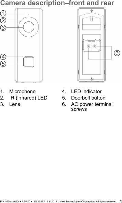
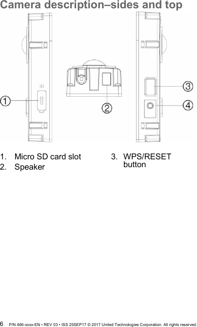
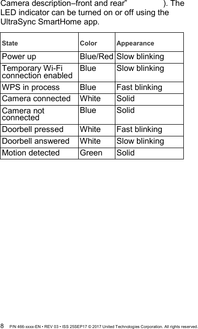
UTC FIRE & SECURITY AMERICAS CORPORATION, INC Wi-Fi Video Doorbell users manual

users manual

 P/N 466-xxxx-EN • REV 03 • ISS 25SEP17 © 2017 United Technologies Corporation. All rights reserved.  1    UltraSync  Wi-Fi Doorbell Camera  Installation Guide              TM
 2  P/N 466-xxxx-EN • REV 03 • ISS 25SEP17 © 2017 United Technologies Corporation. All rights reserved. Contents Product overview ........................................................3 Installation environment ..............................................3 Camera description–front and rear .............................5 Camera description–sides and top .............................6 Doorbell camera LED indicator .............................7 Accessing the Micro SD card ......................................8 Installation Step 1 .......................................................8 Installation Step 2 .......................................................9 Installation Step 3 ..................................................... 10 Installation Step 4 ..................................................... 11 Getting started .......................................................... 12 Operating the doorbell .............................................. 13 Video intercom .................................................... 13 Live view ............................................................. 13 Playback ............................................................. 13 Recording ........................................................... 13 Alarm notification ................................................ 13 Add camera to the network via WPS ........................ 14 TruVision Device Manager ....................................... 14 Troubleshooting ....................................................... 15
 P/N 466-xxxx-EN • REV 03 • ISS 25SEP17 © 2017 United Technologies Corporation. All rights reserved.  3 Product overview This is the installation guide for the following UltraSync IP camera models:  RS-3240 (1080p IP Wi-Fi Doorbell IR camera, US)  RS-3241 (1080p IP Wi-Fi Doorbell IR camera, EMEA) Installation environment When installing the product, consider these factors:  Electrical: The doorbell camera may only be connected to mechanical and digital doorbells that use 16-24 VAC power.    Included transformer: RS-3241 includes an input 16-24 VAC transformer.  Contact a qualified electrician to properly wire according to national and local wiring code.      Wi-Fi: The doorbell camera is only compatible with 2.4 GHz networks.  Ensure that the location planned for the installation of the camera is able to receive a -65 dBM or better Wi-Fi signal.   Network: Recommended at least 768kbps upstream bandwidth for each camera to connect to the internet.  Ventilation: Ensure that the location planned for the installation of the camera is well ventilated.  Temperature: Do not operate the camera beyond the specified temperature, humidity, or power source ratings. The operating temperature of the camera is between -30 to +50°C (-22 to 122°F). Humidity is below 90%.
 4  P/N 466-xxxx-EN • REV 03 • ISS 25SEP17 © 2017 United Technologies Corporation. All rights reserved.  Moisture: Do not expose the camera to rain or moisture, or try to operate it in wet areas. Moisture can damage the camera and also create the danger of electric shock.  Servicing: Do not attempt to service this camera yourself. Any attempt to dismantle this product invalidates the warranty and may also result in serious injury. Refer all servicing to qualified service personnel.  Cleaning: Do not touch the sensor modules with fingers. If cleaning is necessary, use a clean cloth with some ethanol and wipe the camera gently.   Reflectivity: Ensure that there is no reflective surface too close to the camera lens. The IR light from the camera may reflect back into the lens causing reflection.
 P/N 466-xxxx-EN • REV 03 • ISS 25SEP17 © 2017 United Technologies Corporation. All rights reserved.  5 Camera description–front and rear   1.  Microphone 2.  IR (infrared) LED 3.  Lens  4.  LED indicator 5.  Doorbell button 6.  AC power terminal screws
 6  P/N 466-xxxx-EN • REV 03 • ISS 25SEP17 © 2017 United Technologies Corporation. All rights reserved. Camera description–sides and top   1.  Micro SD card slot 2.  Speaker   3.  WPS/RESET button
 P/N 466-xxxx-EN • REV 03 • ISS 25SEP17 © 2017 United Technologies Corporation. All rights reserved.  7 Doorbell camera LED indicator The following table describes the doorbell camera LED behavior (see item 4 in “
 8  P/N 466-xxxx-EN • REV 03 • ISS 25SEP17 © 2017 United Technologies Corporation. All rights reserved. Camera description–front and rear”   ). The LED indicator can be turned on or off using the UltraSync SmartHome app.  State Color Appearance Power up Blue/Red Slow blinking Temporary Wi-Fi connection enabled Blue Slow blinking WPS in process Blue Fast blinking Camera connected White  Solid Camera not connected  Blue  Solid Doorbell pressed White  Fast blinking Doorbell answered White  Slow blinking Motion detected Green  Solid
 P/N 466-xxxx-EN • REV 03 • ISS 25SEP17 © 2017 United Technologies Corporation. All rights reserved.  9 Accessing the Micro SD card A 16 GB Micro SD card is pre-installed in the camera. Micro SD cards with up to 128 GB of storage capacity can also be used. Note: Video and log files stored on the Micro SD card can only be accessed using the UltraSync App when validated with the UltraSync Panel. To access the Micro SD card slot, remove the cover on the side of the camera.     Installation Step 1 Before mounting the doorbell camera:   Ensure that the doorbell’s power supply is shut off during the physical installation/camera mounting.   Ensure that the existing doorbell has been removed with all wires disconnected.
 10  P/N 466-xxxx-EN • REV 03 • ISS 25SEP17 © 2017 United Technologies Corporation. All rights reserved. Installation Step 2 To mount the doorbell camera: 1.  With the rear of the doorbell assembly facing down, gently pull the faceplate off of the assembly. (can we add drawing here?) 2.  Align the cable hole on the mounting template with the cable hole on the mounting surface.  3.  If mounting the doorbell on a stucco, concrete, or brick surface: Drill wall anchor holes according to the drill template using the appropriate drill bit. Press each anchor into the wall after drilling the holes.  If installing the doorbell on a wood surface or into siding: proceed to “Installation Step 3”    .
 P/N 466-xxxx-EN • REV 03 • ISS 25SEP17 © 2017 United Technologies Corporation. All rights reserved.  11 Installation Step 3 To connect the doorbell camera to power: 1.  Connect the existing doorbell wiring to the rear of the doorbell assembly. The two wires can be connected to either terminal on the rear of the assembly.  2.  If the existing wires are not long enough to properly connect the doorbell camera: Use the included connectors and wires to extend the existing wires. Insert the wires into the connector and then tighten the screws until the wire connection is secured. Note: Connect the included resistor to the doorbell if no electrical or mechanical chime is connected.
 12  P/N 466-xxxx-EN • REV 03 • ISS 25SEP17 © 2017 United Technologies Corporation. All rights reserved. 1.  Wires 2.  Connector  3.  10Ω Resistor  Installation Step 4 To finish installing the doorbell camera: 1.  Route the cables and insert the cables and power connector into the wall.  2.  Align the screw holes on the doorbell body with the drilled holes or wall anchors. 3.  Mount the doorbell body to the wall using the two screws provided. 4.  Affix the faceplate to the doorbell body using the  security screw and security screw wrench provided.   1.  Wall screws  2.   Security screw  3.  Turn the power supply to the doorbell camera back on and proceed to “Getting started”   .
 P/N 466-xxxx-EN • REV 03 • ISS 25SEP17 © 2017 United Technologies Corporation. All rights reserved.  13 Getting started Before setting up the doorbell camera for use, follow all of the installation steps and ensure that the doorbell camera is powered on (doorbell LED should be blue slow blinking). Note: For detailed information on how to set up the UltraSync app, add locations, and log in as an installer, see the UltraSync Hub Reference Guide.  To install the UltraSync app and activate the doorbell: 1.  With your mobile device connected to Wi-Fi, download and install the UltraSync + app (appears as UltraSync Home after download).  or  2.  Open the UltraSync app and log in as an installer on the specific site. 3.  Tap the menu icon at the top left of the screen, and then tap New Device Setup. 4.  Follow the on-screen prompts from the app to do the following:   Connect your mobile device to the camera,   Set up a camera user name and password.   Sync the camera to the UltraSync hub.   Change camera names and view camera status.
 14  P/N 466-xxxx-EN • REV 03 • ISS 25SEP17 © 2017 United Technologies Corporation. All rights reserved. Operating the doorbell Use the UltraSync SmartHome app to perform doorbell camera functions.  Video intercom When the doorbell button is pressed, you can receive notification via the app, get the live view from the doorbell camera, and start a 2-way voice communication with the visitor. Live view Launch the app to get a live view of the connected devices. Playback Launch the app and access a connected device to play back video. Recording Record any event-triggered video such as motion detection video with the doorbell camera. Alarm notification Launch the UltraSync app to see alarm messages.
 P/N 466-xxxx-EN • REV 03 • ISS 25SEP17 © 2017 United Technologies Corporation. All rights reserved.  15 Add camera to the network via WPS A WPS-enabled wireless router is required to add a camera using the WPS function. 1. Press the WPS button on the router. 2. Within 120 seconds of pressing the WPS button on the router, press the WPS button on the camera for approximately five seconds. See “Camera description” on page 5 and 6 for WPS button and LED locations. 3. The blue LED on the camera flashes rapidly to indicate that it starts the WPS process.  White LED will be on when the camera has joined the wireless network.  TruVision Device Manager The TruVision® Device Manager is standalone software that can discover TruVision IP devices on a network.  In addition to finding device IP addresses, camera password can be activated, IP settings can be changed and camera FW can be update through Device Manager.
 16  P/N 466-xxxx-EN • REV 03 • ISS 25SEP17 © 2017 United Technologies Corporation. All rights reserved. Troubleshooting  Troubleshooting/FAQ 1. The camera does not appear in the list of Wi-Fi networks. Cause Solution The camera takes up to 90 seconds to boot up.   Wait until the camera boots up before checking the Wi-Fi list. Another user is currently setting up the camera using the recommended method or the camera has previously been set up using the recommended method.   Perform a factory reset by holding the WPS/RESET button for 15 seconds to rebroadcast the camera. 2. The camera does not add to the UltraSync network when Scan for Cameras is selected. Cause Solution The camera will not work if the devices are not on the same network. Make sure the camera and the UltraSync Hub panel are on the same network. UltraSync Hub must be using IP to work with the cameras. Ensure that the UltraSync Hub panel is not installed using a cellular radio only.   Ensure that cameras are not being added to a network that already has a high number of cameras installed on the same network. This is unusual, but may be common in testing environments.   Put UltraSync Hub and the cameras on their own router. 3. The camera was added in the setup process, but the video doesn’t show in the Cameras tab.
 P/N 466-xxxx-EN • REV 03 • ISS 25SEP17 © 2017 United Technologies Corporation. All rights reserved.  17 Cause Solution After completing the setup process, the camera may take up to two minutes to appear in the UltraSync App. Wait for the process to complete  Make sure the camera is still connected to the network.  If video still doesn’t appear, go back into setup and perform the “Scan for Cameras” function.
 18  P/N 466-xxxx-EN • REV 03 • ISS 25SEP17 © 2017 United Technologies Corporation. All rights reserved. 4. Live Video quality is poor. It is choppy, shows gray, etc. Cause Solution Ensure that the camera’s Wi-Fi and/or Ethernet connection speeds are adequate (768 Kbps minimum). If Wi-Fi connection speeds are poor, we recommend using a  Wi-Fi repeater to increase signal strength. The camera’s default settings are set up to work on a strong home network.   In some cases, low video settings may be required to achieve a smooth video. Change to SD mode from the mobile app 5. Video Clips take a long time to load. Cause Solution The camera’s default settings are configured to have video clips start playing in the UltraSync app within 15 seconds (on a strong network). If default settings were changed to longer clip times or higher video quality, the amount of time needed to access the clip increases.   Lower the quality or length of clips to shorten load times.  Copyright © 2017 United Technologies Corporation.  Interlogix is part of UTC Climate, Controls & Security, a unit of United Technologies Corporation. All rights reserved.
 P/N 466-xxxx-EN • REV 03 • ISS 25SEP17 © 2017 United Technologies Corporation. All rights reserved.  19 Trademarks and patents The UltraSync and TruVision names and logos are trademarks of United Technologies.  Other trade names used in this document may be trademarks or registered trademarks of the manufacturers or vendors of the respective products. Manufacturer Interlogix 2955 Red Hill Avenue, Costa Mesa, CA 92626-5923, USA Authorized EU manufacturing representative: UTC Fire & Security B.V. Kelvinstraat 7, 6003 DH Weert, The Netherlands Certification      FCC compliance Class B: This equipment has been tested and found to comply with the limits for a Class B digital device, pursuant to part 15 of the FCC Rules. These limits are designed to provide reasonable protection against harmful interference when the equipment is operated in a commercial environment. This equipment generates, uses, and can radiate radio frequency energy and, if not installed and used in accordance with the instruction manual, may cause harmful interference to radio communications. Operation of this equipment in a residential area is likely to cause harmful interference in which case the user will be required to correct the interference at his own expense. FCC conditions This device complies with Part 15 of the FCC Rules. Operation is subject to the following two conditions:  (1) This device may not cause harmful interference. (2) This Device must accept any interference received, including interference that may cause undesired operation. Federal Communication Commission (FCC) Radiation Exposure Statement This equipment complies with FCC radiation exposure set forth for an uncontrolled environment. In order to avoid the possibility of exceeding the FCC radio frequency exposure limits, human proximity to the antenna shall not be less than 20 cm (8 inches) during normal
 20  P/N 466-xxxx-EN • REV 03 • ISS 25SEP17 © 2017 United Technologies Corporation. All rights reserved. operation. CAUTION: Changes or modifications not expressly approved by UTC for compliance could void the user’s authority to operate the equipment. RS-3230/RS-3231/TVQ-8101 COMPLIES WITH FCC PART C, FCC ID: 2AENJ-RS324X RS-3250/RS-3251/TVB-8101 COMPLIES WITH FCC PART C, FCC ID: 2AENJ-RS324X ACMA compliance Notice! This is a Class A product. In a domestic environment this product may cause radio interference in which case the user may be required to take adequate measures. Canada This Class B digital apparatus complies with CAN ICES-003 (B)/NMB-3 (B).  Cet appareil numérique de la classe B est conforme à la norme CAN ICES-003  (B)/NMB-3 (B). Canadian Compliance  This Class B digital apparatus meets all requirements of the Canadian Interference Causing Equipment Regulations. Cet appareil numérique de la classe B respects toutes les exigences du Règlement sur le matériel brouilleur du Canada. Canada - Industry Canada (IC)  The wireless radio of this device complies with RSS 247 and RSS 102 of Industry Canada. This Class B digital device complies with Canadian ICES-003 (NMB-003). Cet appareil numérique de la classe B respects toutes les exigences du Règlement sur le matériel brouilleur du Canada. This device complies with Industry Canada’s licence-exempt RSSs. Operation is subject to the following two conditions:  (1) This device may not cause interference; and  (2) This device must accept any interference, including interference that may cause undesired operation of the device.  Le présent appareil est conforme aux CNR d'Industrie Canada applicables aux appareils radio exempts de licence. L'exploitation est autorisée aux deux conditions suivantes :  (1) l'appareil ne doit pas produire de brouillage, et
 P/N 466-xxxx-EN • REV 03 • ISS 25SEP17 © 2017 United Technologies Corporation. All rights reserved.  21 (2) l'utilisateur de l'appareil doit accepter tout brouillage radioélectrique subi, même si le brouillage est susceptible d'en compromettre le fonctionnement.  RS-3230/RS-3231/TVQ-8101 complies with IC requirements, IC: 20201-RS324X. RS-3250/RS-3251/TVB-8101 complies with IC requirements, IC: 20201-RS324X. This radio transmitter (IC: 20201-RS3130) has been approved by Industry Canada to operate with the antenna types listed below with the maximum permissible gain indicated. Antenna types not included in this list, having a gain greater than the maximum gain indicated for that type, are strictly prohibited for use with this device.   Internal (Default): 2.4dBi directional antenna  Le présent émetteur radio (IC: 20201-RS31130) a été approuvé par Industrie Canada pour  fonctionner avec les types d'antenne énumérés ci-dessous et ayant un gain admissible maximal et l'impédance requise pour chaque type d'antenne. Les types d'antenne non inclus dans cette liste, ou dont le gain est supérieur au gain maximal indiqué, sont strictement interdits pour l'exploitation de l'émetteur.      intégré 2.4dBi antenne  European Union directives This product and - if applicable - the supplied accessories too are marked with "CE" and comply therefore with the applicable harmonized European standards listed under the EMC Directive 2014/30/EU, the RoHS Directive 2011/65/EU and Directive:2014/35/EU (LVD). R&TTE Compliance Statement This equipment complies with all the requirements of DIRECTIVE 1999/5/CE OF THE EUROPEAN PARLIAMENT AND THE COUNCIL OF 9 March 1999 on radio equipment and telecommunication terminal Equipment and the mutual recognition of their conformity (R&TTE).  Safety This equipment is designed with the utmost care for the safety of those who install and use it. However, special attention must be paid to the dangers of electric shock and static electricity when working with electrical equipment. All guidelines of this and of the computer manufacture
 22  P/N 466-xxxx-EN • REV 03 • ISS 25SEP17 © 2017 United Technologies Corporation. All rights reserved. must therefore be allowed at all times to ensure the safe use of the equipment. Installation must at all times conform to local regulations.  2012/19/EU (WEEE directive): Products marked with this symbol cannot be disposed of as unsorted municipal waste in the European Union. For proper recycling, return this product to your local supplier upon the purchase of equivalent new equipment, or dispose of it at designated collection points. For more information see: www.recyclethis.info.  2013/56/EU (battery directive): This product contains a battery that cannot be disposed of as unsorted municipal waste in the European Union. See the product documentation for specific battery information. The battery is marked with this symbol, which may include lettering to indicate cadmium (Cd), lead (Pb), or mercury (Hg). For proper recycling, return the battery to your supplier or to a designated collection point. For more information see: www.recyclethis.info. Contact information and manuals For contact information and to get translations for this and other product manuals go to: www.interlogix.com or www.utcfssecurityproducts.eu.
 P/N 466-xxxx-EN • REV 03 • ISS 25SEP17 © 2017 United Technologies Corporation. All rights reserved.  23  Annex 3 B and A Wideband Data Transmission systems 2400.0-2483.5 MHz: Country Restriction Reasons/remarks Norway Implemented This subsection does not apply for the geographical area within a radius of 20 km from the centre of Ny-Ålesund. Italy Implemented The public use is subject to general authorization by the respective service provider. Russian Federation Limited implementation 1. SRD with FHSS modulation 1.1. Maximum 2.5 mW e.i.r.p. 1.2. Maximum 100 mW e.i.r.p. Permitted for use SRD for outdoor applications without restriction on installation height only for purposes of gathering telemetry information for automated monitoring and resources accounting systems. Permitted to use SRD for other purposes for outdoor applications only when the installation height is not exceeding 10 m above the ground surface. 1.3 maximum 100 mW e.i.r.p. indoor applications. 2. SRD with DSSS and other than FHSS wideband modulation 2.1. Maximum mean e.i.r.p. density is 2 mW/MHz.  Maximum 100 mW e.i.r.p. 2.2. Maximum mean e.i.r.p. density is 20 mW/MHz. Maximum 100 mW e.i.r.p. It is permitted to use SRD for outdoor applications only for purposes of gathering telemetry information for automated monitoring and resources accounting systems or security systems. 2.3. Maximum mean e.i.r.p. density is 10 mW/MHz. Maximum 100 mW e.i.r.p. indoor applications. Ukraine Limited implementation e.i.r.p. ≤100 mW with built-in antenna with amplification factor up to 6 dBi.
 24  P/N 466-xxxx-EN • REV 03 • ISS 25SEP17 © 2017 United Technologies Corporation. All rights reserved.  PRODUCT WARNINGS  A PROPERLY INSTALLED AND MAINTAINED ALARM/SECURITY SYSTEM MAY ONLY REDUCE THE RISK OF EVENTS SUCH AS BREAK-INS, BURGLARY, ROBBERY OR FIRE; IT IS NOT INSURANCE OR A GUARANTEE THAT SUCH EVENTS WILL NOT OCCUR, THAT ADEQUATE WARNING OR PROTECTION WILL BE PROVIDED, OR THAT THERE WILL BE NO DEATH, PERSONAL INJURY, AND/OR PROPERTY DAMAGE AS A RESULT.   WHILE INTERLOGIX UNDERTAKES TO REDUCE THE PROBABILITY THAT A THIRD PARTY MAY HACK, COMPROMISE OR CIRCUMVENT ITS SECURITY PRODUCTS OR RELATED SOFTWARE, ANY SECURITY PRODUCT OR SOFTWARE MANUFACTURED, SOLD OR LICENSED BY INTERLOGIX, MAY STILL BE HACKED, COMPROMISED AND/OR CIRCUMVENTED.    INTERLOGIX DOES NOT ENCRYPT COMMUNICATIONS BETWEEN ITS ALARM OR SECURITY PANELS AND THEIR OUTPUTS/INPUTS INCLUDING, BUT NOT LIMITED TO, SENSORS OR DETECTORS UNLESS REQUIRED BY APPLICABLE LAW.   AS A RESULT THESE COMMUNICATIONS MAY BE INTERCEPTED AND COULD BE USED TO CIRCUMVENT YOUR ALARM/SECURITY SYSTEM.  WARRANTY DISCLAIMERS   INTERLOGIX HEREBY DISCLAIMS ALL WARRANTIES AND REPRESENTATIONS, WHETHER EXPRESS, IMPLIED, STATUTORY OR OTHERWISE INCLUDING (BUT NOT LIMITED TO) ANY WARRANTIES OF MERCHANTABILITY OR FITNESS FOR A PARTICULAR PURPOSE WITH RESPECT TO ITS SECURITY PRODUCTS AND RELATED SOFTWARE.   INTERLOGIX FURTHER DISCLAIMS ANY OTHER IMPLIED WARRANTY UNDER THE UNIFORM COMPUTER INFORMATION TRANSACTIONS ACT OR SIMILAR LAW AS ENACTED BY ANY STATE.  (USA only) SOME STATES DO NOT ALLOW THE EXCLUSION OF IMPLIED WARRANTIES, SO THE ABOVE EXCLUSION MAY NOT APPLY TO YOU.  THIS WARRANTY GIVES YOU SPECIFIC LEGAL RIGHTS AND YOU MAY ALSO HAVE OTHER LEGAL RIGHTS THAT VARY FROM STATE TO STATE.  INTERLOGIX MAKES NO REPRESENTATION, WARRANTY, COVENANT OR PROMISE THAT  ITS SECURITY PRODUCTS AND/OR RELATED SOFTWARE (I) WILL NOT BE HACKED, COMPROMISED AND/OR CIRCUMVENTED; (II) WILL PREVENT, OR PROVIDE ADEQUATE WARNING OR PROTECTION FROM, BREAK-INS, BURGLARY, ROBBERY, FIRE; OR (III) WILL WORK PROPERLY IN ALL ENVIRONMENTS AND APPLICATIONS.

Navigation menu