UTC Fire and Security Americas 569E-LMRISE Rate of Rise Transmitter User Manual
UTC Fire & Security Americas Corporation, Inc. Rate of Rise Transmitter
User Manual
P/N 46-547 • REV H • January 2011 1
Learn Mode Rate of Rise Heat Sensors
Installation Instructions
Introduction
This is the Learn Mode Rate-of-Rise Heat Sensors
Installation Instructions. The sensors (Figure 1) combine a
Chemetron heat detector and a learn mode wireless
transmitter in one unit. A built-in thermostat trips the transmitter
when the temperature at the sensor location reaches about
135°F (57°C) or 200°F (94°C), depending on the model
installed.
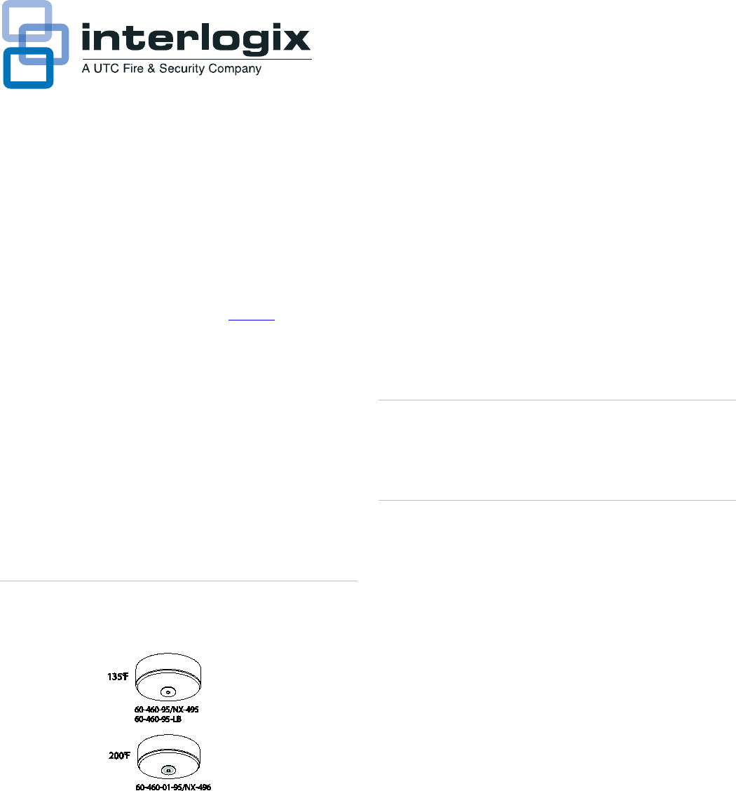
135°F models
60-460-95/NX-495, 60-460-95-LB
200°F models
60-460-01-95/NX-496
Figure 1. Sensor models
Since many fires grow rapidly in intensity causing a rapid
temperature increase, the thermostat also trips the transmitter
if the temperature rises 15°F (8°C) or more per minute.
All models can be powered by one 9-volt alkaline battery that
can last 12 to 18 months, or by one 9-volt lithium battery that
can last up to twice as long.
Note: Battery life depends on how often the sensor transmits
signals, but is more dependent on the temperature of the
installation environment. Alkaline batteries self-discharge more
rapidly when used in high temperature environments.
When the battery voltage gets low, the sensor transmits a low
battery signal to the panel. The panel then activates sirens with
trouble beeps to notify the customer that the sensor battery
must be replaced
Caution: SX-V Special panels must have software version 8.0
or later installed for correct response from the sensors. Do not
install Learn Mode Rate of Rise Heat sensors if the panel an
earlier software version. Contact Interlogix technical support at
888.437.3287 for assistance.
Installation
Use the following installation guidelines:
• Heat sensors should be installed to provide property
protection. Reliance should not be placed on heat
detectors for life safety. Where life safety is involved,
smoke sensors must also be installed.
• The sensors allow for normal temperature fluctuations,
however, ceiling temperatures should not exceed 100°F
(37°C) when installing 135°F models, or 150°F (66°C)
when installing 200°F models.
• Mount the sensor in a central location of the area to be
protected, either on the ceiling or on a wall.
• If mounting on a ceiling, the sensor must be at least 4 in.
(10 cm) away from any walls.
• If mounting on a wall, the top of the sensor must be within
4 to 6 in. (10 to 15 cm) of the ceiling.
• The UL maximum spacing allowance of the sensor is 50 x
50 ft. (15 x 15 m). Refer to the NFPA Standard 72 for
application requirements.
2 Learn Mode Rate of Rise Heat Sensors Installation Instructions
• Do not mount the sensor close to devices that change
temperature rapidly, such as ovens, heat vents, furnaces,
or boilers.
Equipment needed
You will need the following equipment to install the sensors:
• Phillips and flathead screwdrivers
• Appropriate learn mode control panel documentation (for
programming information)
Programming
The panel must learn (program) the sensor ID code in order to
respond to sensor signals. For complete programming
information, refer to the specific control panel documentation.
To add the sensor to panel memory, do the following:
1. Separate the sensor from the base by twisting the sensor
counter-clockwise and pulling the sensor off the base. Set
the base aside.
2. Place the panel in program mode.
3. Proceed to the Learn Sensors menu. When the panel
prompts you for a sensor group number, enter the group
number (26).
4. Select the desired sensor number.
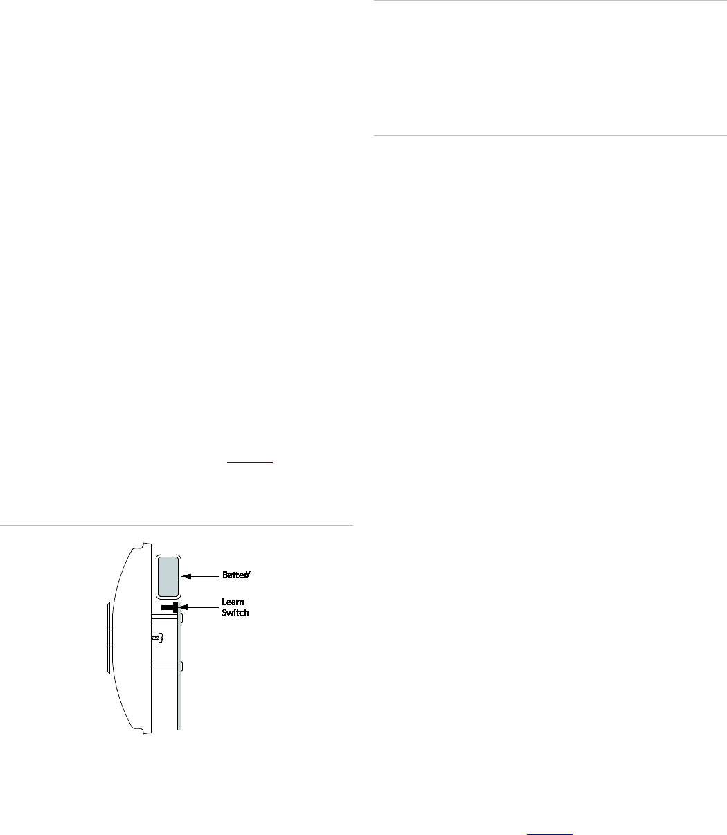
5. When the panel prompts you to trip the sensor, press and
hold the learn switch on the sensor (Figure 2) until the
panel beeps, indicating successful programming.
Figure 2. Learn switch
6. Exit program mode.
Testing
Before permanently securing the sensor to the wall or ceiling,
test the sensor from the installation location using one of the
following methods.
Caution: The test method described only tests rate-of-rise
operation. These sensors cannot be field tested for their fixed
temperature ratings without being destroyed. When used with
care, the heat from a portable hair dryer (method 2) can be
used for testing. Do not aim the hair dryer directly at the round
disc on the sensor as this can cause it to pop off. If this
happened, the sensor must be replaced.
Method 1
To test the sensor, do the following:
1. Place the panel in sensor test mode.
2. Rub your hands together vigorously, until they feel hot.
3. Place the palm of one hand on the round disc of the
sensor, for about 7 to 10 seconds.
4. Listen for the appropriate number of beeps from interior
sirens and speakers (refer to the specific panel
documentation).
5. Exit sensor test mode.
The sensor should reset in less than one minute.
Method 2
To test the sensor, do the following:
1. Place the panel in sensor test mode.
2. Plug in a portable hair dryer.
3. Hold the hair dryer about 12 to 18 in. away from the
sensor, aiming it at the side of the sensor.
4. Listen for the appropriate number of beeps from interior
sirens and speakers (refer to the specific panel
documentation).
5. Exit sensor test mode.
The sensor should reset in less than one minute.
Mounting the sensor
To secure the sensor to its permanent location, do the
following:
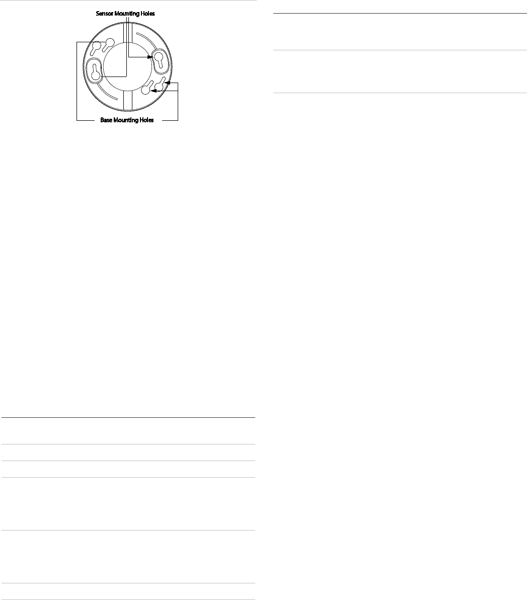
1. Locate the base mounting holes (inner pair and outer pair)
and mount the base to the wall or ceiling with the
appropriate hardware (Figure 3).
2. Attach the sensor to the base.
Learn Mode Rate of Rise Heat Sensors Installation Instructions 3
Figure 3. Mounting holes
Replacing the batteries
When the sensor battery gets low, the sensor transmits a low
battery signal. The panel receives this signal and sounds
trouble beeps through the system sirens. Pressing the Status
button identifies the sensor with the low battery.
Replace the battery immediately when this condition occurs,
using the following batteries: Eveready© 9-Volt Alkaline
Energizer (No. 522); Duracell© 9-Volt Alkaline (MN1604); or
UltraLife© 9-Volt Lithium.
Battery disposal
Alkaline and lithium batteries that are not longer usable are
considered hazardous waste. Be sure to properly dispose of
the old batteries according to your local hazardous waste
disposal laws.
Specifications
Compatibility
Interlogix/GE Learn Mode panels and
receivers
Frequency
319.5 MHz
Power requirements
One 9-volt alkaline or lithium battery
Operating temperature
60-460-95/NX495, 60-460-95-LB:
40 to 100°F (4 to 37°C)
60-460-01-95/NX-496:
32 to 150°F (0 to 66°C)
Storage temperatu
re 60-460-95/NX-495, 60-460-95-LB:
-30 to 120°F (-34 to 48°C)
60-460-01-95/NX-496:
-30 to 140°F (-34 to 60°C)
Maximum humidity
90% relative humidity, noncondensing
Dimensions
4.4 in. (11.18 cm) diameter x 2.2 in. (5.59 cm)
depth
Regulatory information
M
anufacturer UTC Fire & Security Americas Corporation, Inc.
1275 Red Fox Rd., Arden Hills, MN 55112-6943,
USA
UL
listings UL 985 Household Fire Warning System Units
UL 521 Heat Detectors for Fire Protective
Signaling Systems
This equipment has been tested and found to comply with the limits for a
Class B digital device, pursuant to Part 15 of the FCC Rules. These limits are
designed to provide reasonable protection against harmful interference in a
residential installation.
This equipment generates, uses
and can radiate radio frequency energy and,
if not installed and used in accordance with the instructions, may cause
harmful interference to radio communications. However, there is no
guarantee that interference will not occur in a particular installation.
If this equipment does cause harmful interference to radio or television
reception, which can be determined by turning the equipment off and on, the
user is encouraged to try to correct the interference by one or more of the
following measures:
• Reorient or relocate the receiving antenna.
• Increase the separation between the equipment and receiver.
• Connect the equipment into an outlet on a circuit different from that to
which the receiver is connected.
• Consult the dealer or an experienced radio/TV technician for help.
Changes or modifications not expressly approved by UTC Fire and Security
could void the user’s authority to operate the equipment.
This device complies with Industry Canada licence-exempt RSS standard(s).
Operation is subject to the following two conditions: (1) this device may not
cause interference,and (2) this device must accept any interference,
including interference that may cause undesired operation of the device.
Cet appareil est conforme avec Industrie Canada exempts de licence
standard RSS (s). Son fonctionnement est soumis aux deux conditions
suivantes: (1) cet appareil ne doit pas provoquer d'interférences et (2) cet
appareil doit accepter toute interférence, y compris celles pouvant causer un
mauvais fonctionnement de l'appareil.
In accordance with FCC requirements of human exposure to radiofrequency
fields, the radiating element shall be installed such that a minimum
separation distance of 20 cm is maintained from the general population.
FCC: B4Z-569E-LMRISE
IC: 1175C-569EROR
This Class B digital apparatus complies with Canadian ICES-003.
Cet appareil numérique de la classe B est conforme à la norme NMB-
003 du
Canada.
Contact information
For contact information, see www.utcfireandsecurity.com or
www.interlogix.com.
For technical support, toll-free: 888.437.3287 in the US
including Alaska, Hawaii, Puerto Rico, and Canada. Outside
the tool-free area, contact your dealer.
GE is a trademark of the General Electric Company and is
under license to UTC Fire & Security, 9 Farm Springs Road,
Farmington, CT 06034-4065
Copyright © 2011 Interlogix, a UTC Fire & Security Company.
All rights reserved.