UTC Fire and Security Americas 5845GB-Z WIRELESS GLASS BREAK DETECTOR User Manual USERS MANUAL
UTC Fire & Security Americas Corporation WIRELESS GLASS BREAK DETECTOR USERS MANUAL
USERS MANUAL
UTC. All Rights Reserved. 1 P/N 0000000 – Rev. A – 06 Nov 12
5845GBW-OEM
Glass Break Detector
Product Introduction
The 5845GBW Glass Break Detector (product) is ideal for applications
where hardwired acoustic sensors are impractical, listens for actual
patterns of breaking glass using Pattern Recognition Technology™
across the full audio band. The factory set recognition patterns detect
breaking glass of framed perimeter windows in a building vs. a
drinking glass breaking within a room. This product features a 20-ft. (6
m) range from sensor to glass.
The product is suitable for use in quiet occupied areas on the perimeter
loop. The sensor’s low-profile housing conceals the wireless transmitter
and battery.
A simple hand clap feature lets the user confirm that the sensor is
operational, or a handheld tester can be activated at close range.
This wireless Glass Break Detector complies with the ANSI/UL 639
standard for Intrusion products. It is intended for residential indoor
dwelling unit applications and other areas approved by the authority
having jurisdiction (AHJ). It is not intended for use in industrial
applications.
This product operates in conjunction with your wireless Control Panel,
providing a local indication. Refer to the panel installation instructions
for revision verification details. Please contact Technical Support for any
questions regarding compatibility.
About This Guide
This User Guide describes how to install, the operation and
maintenance of this product. The User Guide is organized as you intent
to use this product with step by step instructions.
Keep this document in a handy location and refer to it when you have
questions about this product and its functions and features. Reading
this guide is the only way to learn how to use your product wisely and
to know how to react in the event of an alarm.
Attention: Please take a few minutes to thoroughly read this
guide which should be saved for future reference and passed on to
any subsequent owner.
1. General Information
Congratulations on purchasing your Glass Break Detector. This product is
designed to be used with a Control Panel as an intrusion signaling
device.
Install the sensor on a perimeter loop armed whenever the door and
window contacts are armed. Avoid 24-hour loop applications where
the sensor is armed all day and all night. The false-alarm technology
will be pushed to its limit in a 24-hour loop.
The sensor’s false-alarm immunity is best in rooms with only moderate
noise. Some sounds can duplicate the points on the glass break
pattern the sensor detects. The sensor may not consistently detect
cracks in glass, or bullets which break through the glass. Glass break
sensors should always be complemented with interior protection.
Parts List
One Glass Break Detector
One CR123 Lithium Battery
Mounting Screws and Anchors
User Guide
2. Mounting Guideline
This product is a member of a reliable, high-quality product family
using the latest technology available. Review the information in this
section to ensure you get the most out of the product.
Choosing an Installation Location
The sensor must always be in direct line of sight of all windows to be
protected. The sensor cannot consistently detect glass breaking around
corners or in other rooms. There is no required front, back, up or down
orientation.
Wall mount…
The best wall-mount location is on the opposite wall, assuming the
glass to be protected is within the sensor’s range and line of sight. The
adjoining wall can also be used.
Ceiling mount…
Mount the sensor in a location that is in direct line of sight of the glass
to be protected. However, since sound travels directionally out from a
broken window, a position 8 ft. (2.4 m) into the room provides better
detection.
Use the following guidelines to determine the best mounting location:
o Mount the sensor at least 3.3 ft. (1 m) from the windows being
protected and at least 4 ft. (1.2 m) from noise sources such as
TVs, speakers, sinks, and doors.
o Mount the sensor in the direct line of sight of the glass to be
protected.
o Mount the sensor in a suitable environment: temperature
between 0 and 120°F (-18 and 50°C); and humidity between 10
and 90% non-condensing.
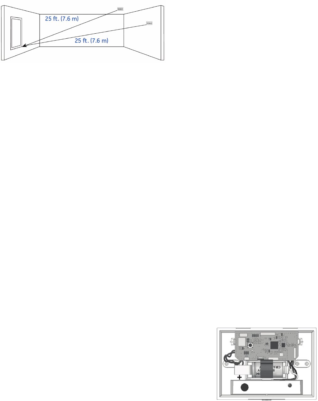
o Mount the sensor on a stable surface up to 25 ft. (7.6 m) from
the farthest point on the glass surface.
Recommended locations and Range
The sensor is omni-directional, providing 360° coverage. Coverage is
measured from the sensor to the point on the glass farthest from the
sensor. The sensor can be mounted as close as 3.3 ft. (1 m) from the
glass. The maximum range depends on the type of glass being
protected:
o Armor-coated glass - Mount sensor no more than 12 ft. (3.6 m)
from the glass.
o Plate, tempered, laminated, and wired glass - Mounted on
the ceiling or the opposite or adjoining wall, maximum range is
25 ft. (7.6 m).
UTC. All Rights Reserved. 2 P/N 0000000 – Rev. A – 06 Nov 12
Locations to avoid
Improper location can affect the sensitive electronic components in this
product. To avoid causing damage to the product, to provide optimum
performance, and to prevent unnecessary nuisance alarms:
o Avoid rooms smaller than 10 x 10 ft. (3m x 3m).
o Avoid locations where lined, insulating, or sound-deadening
drapes or closed wooden shutters are used.
o Corner of a room.
o Do not install the sensor in humid rooms. Excess moisture on
the circuit board can eventually cause a short and a false
alarm.
o Avoid locations that expose the sensor to possible false alarm
sources such as:
− glass airlocks and vestibule areas
− kitchens
− corner mounting
− residential car garages
− small utility rooms
− stairwells
− bathrooms
− small acoustically live rooms.
− locations exposed to white noise, such as air
compressors, etc.
3. Mounting the Sensor
Note: Add the product to the Control Panel before physically mounting
the product in the desired location. This verifies RF performance prior to
permanently mounting the alarm. See “RF Communication Test”.
To mount the alarm:
This product can be wall mounted or ceiling mounted.
A. Disconnect alarm-notification appliances, service-release devices,
and extinguishing systems. Test communications between the
control panel and the product before permanently mounting as
follows:
− Hold the product where you plan to install it.
− Hold the glass break tester next to the glass break’s
microphone sensor and press the test button on the glass
break tester. The product sends a signal to the control panel.
− At the control panel, verify the signal was received and RF
signal strength is adequate. If no signal is received or the RF
signal is low, relocate the product and retest.
B. Using two supplied screws and anchors, mount the base of the
product as follows:
- Remove the screw located in the front.
- Remove the top cover by using a flat bladed tool in the screw
location to pry open the top cover.
- Locate the mounting location and drill holes in base per the
mounting impression in the base.
- Use the anchors and screws to secure the product to the
mounting surface.
C. Replace the product’s top cover:
− Snap the top onto the base.
− Replace the screw into the front location.
4. Basic Operations
This product is equipped with an intuitive normal mode operation.
Since the batteries are pre-installed, remove the battery pull tab to turn
ON power. The product shall search for a networked control panel to
pair with. During this time, Search Mode, the RF wireless module
transmits every ~ 5-seconds. Not pairing or enrolling into a control
panel within minutes of initial power up, places a large drain the
batteries. Failure to complete pairing results in dead batteries after 2-3
days time passes.
Normal Mode Operation
o In normal operation, the red LED remains OFF.
o In wake up, the red LED flashed ON with two quick flashes.
o In alarm mode, the red LED stays ON for 4 seconds. Sends an
alarm message to the control panel.
o In trouble or maintenance mode, the red LED does not activate
after a wake up test.
o In low battery mode, a message is sent to the control panel.
Note: the modes can be viewed from the Control Panel.
5. Installing / Replacing Battery
This product comes with one battery preinstalled. When you need to
replace the battery, use the following procedure.
Note: Place the control panel into sensor test mode prior to replacing
the batteries. If the control panel is not in sensor test mode during
battery replacement, an alarm/tamper condition may be indicated.
A. Remove the product top cover.
B. If replacing the battery, remove the old battery and properly
dispose of it as recommended by the battery manufacturer.
C. Install the new battery. Note the polarity illustration in the battery
compartment.
D. Replace the top cover.
E. Replace the front screw.
When replacing the battery, use one of the following approved brands:
o Duracell Ultra

UTC. All Rights Reserved. 3 P/N 0000000 – Rev. A – 06 Nov 12
o Panasonic
Note: Use of a different battery may have a detrimental effect on the
product’s operation. Constant exposures to high or low humidity may
reduce battery life.
After installing or changing the batteries, reinstall the product’s top
cover. Test your product by a wake up test.
6. Adding to the Control Panel
Each product is programmed with a unique ID when manufactured.
The unique ID is enrolled into the control panel at the time of
installation, allowing the product to communicate with that specific
control panel.
A. Log in to the Settings app with an Installer code.
B. In the Settings menu, tap Sensors & Zones > Add a Sensor/Zone.
C. Place the product in Search mode and prepare it to be added to
the control panel (refer to the installation documentation for your
sensors). Available sensors meet the following requirements:
o Defaulted.
o Not currently paired with another control panel device.
o Currently in Search mode.
D. At the Locating Wireless Sensors screen, tap Next. A Done button
appears on the screen and the control panel searches for sensors
that are available to be added. As sensors are found, a grayed
icon appears for that sensor.
E. Fault each found sensor to pair it to the control panel. The icon for
each sensor is undarkened as it is faulted and the control panel
beeps. The sensor is paired to the control panel.
F. When all the sensors are found and paired, tap Stop. Any located
sensors that were not paired are released by the control panel
and can be added later. The Wireless Sensors Located screen
shows the number of wireless sensors found and paired.
G. Tap Next. The Configure Wireless Sensors screen shows icons of
the sensors that were found and paired.
H. Touch each sensor icon to configure the corresponding product.
The Add Sensor/Zone Modify screen appears.
I. To change the product Icon (if multiple options are available), tap
the currently selected value.
J. Tap Next. The Add Sensor/Zone Modify screen appears.
K. To modify a text field on the control panel, tap the field, use the
onscreen keyboard to enter your changes, and tap Done to save
your changes.
L. When all sensors are configured properly, tap Next in the
Configure Wireless Sensors screen.
M. If all of the sensors have not been configured, the Modify screen
appears for each sensor to let you review its details. Change the
details as needed or tap Next to cycle through all the sensors. The
sensors are marked as configured.
7. Testing the Product
This product may be tested during install or at anytime. It is
recommended the product be tested in place annually. This product is
sealed. The cover is not removable.
WARNING: The control panel must be placed into sensor test
mode while conducting any tests. Placing the control panel into sensor
test mode for all testing helps to protect against false alarms and
unintentional central station reporting.
This product has three test methods:
o Wake Up Test. A hand clap should wake up the glass break
detector.
o RF Communication Test. Tests the communication path with
the control panel.
o Glass Break Functional Test. Tests the functional operation of
the glass break sensing element.
Wake Up Test
To test the product locally is to clap your hands loudly above the sensor
and verify that the LED blinks twice. This test verifies that the product is
receiving power, and the microphone and circuit board are working
properly. It does not trip the sensor. The hand clap is only a momentary
test, so there is no significant affect on battery life.
Note: Room acoustics can artificially extend the range of a glass-break
sensor. The specified range of the sensor is set for worst-case
conditions. While it may work at extended range, it can miss a
minimum output break or room acoustics may change over time,
bringing sensor range back into normal 2-foot (6 m) conditions. Do not
exceed the rated range of the sensor, regardless of the tester results.
RF Communication Test
This section provides general guidelines for testing the product with the
control panel. For complete testing details, refer to the specific control
panel documentation.
A. Be sure the product is normal operation.
B. Set the control panel to sensor test mode to prevent an alarm
signal from being sent to the central-monitoring station if you
have a monitored system.
C. To generate a test alarm, remove the top cover generating a
tamper alarm. If the product is operating properly, an alarm
message is sent to the control panel.
D. The control panel beeps and shows the number of RF packets
received.
E. At the panel, exit sensor test mode.
Glass Break Functional Test
The product is designed to detect the breaking of framed glass
mounted in an outside wall. Testing the sensor with unframed lass,
broken bottles, etc., may not trip the sensor. The sensor typically does
not trip to glass breaking in the middle of the room. In rooms where
multiple sounds can reflect and duplicate the glass-break frequency
pattern. The Pattern Recognition Technology of the sensor ignores most
false alarm sounds, including glass break testers. To test the sensor,
use test mode. Test mode disables glass break pattern processing in
upper and lower frequencies. The sensor is then listening only for the
mid-range frequencies that the 5709C hand-held tester reproduces. It’s
the mid-range frequencies that determine sensor range.
Test Mode - To put the sensor in test mode, do the following:
A. Set the control panel to sensor test mode.
B. Use the 5709C handheld tester to put the sensor into test mode.
Set the tester to tempered glass and hold the tester on top of the
sensor.
C. Activate the tester. The sensor will alarm, then go into test mode
for one minute. In test mode, the LED will blink continuously. To
UTC. All Rights Reserved. 4 P/N 0000000 – Rev. A – 06 Nov 12
extend test time, fire the tester at the sensor at least once a
minute.
D. The control panel will beep and display the number of RF
packets received.
E. At the control panel, exit sensor test mode.
Sensor Test Mode - To put the sensor in sensor test mode, do the
following:
A. The tester has a different setting for each type of glass. Set the
tester for tempered or laminated glass unless you are certain
that all the glass to be protected is plate glass.
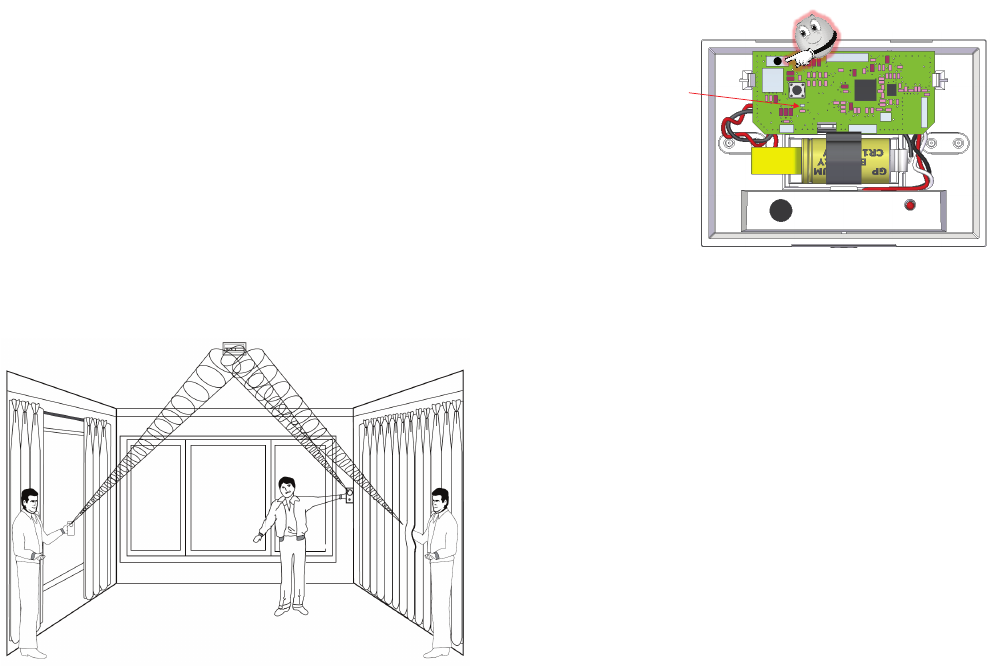
B. Hold the tester near the surface of the glass to be protected
and aim the speaker at the sensor. Be sure the tester is at the
point on the glass farthest from the detector. If closed drapes
or curtains are present, hold the tester behind them.
Press the test button on the tester. The LED on the sensor should stay
on for 4 seconds to indicate the glass is within detection range of the
sensor. If the LED does not stay on for 4 seconds, move the sensor and
retest.
If the sensor will not activate within its stated range of coverage, check
for battery strength in the tester. A new tester battery will likely restore
range. You may need to use additional sensors to achieve adequate
coverage.
The sensor will automatically change from test mode to normal mode
approximately one minute after it last hears the tester. In normal mode
the LED does not blink unless it hears a loud sound. In normal mode,
the sensor will not trip to the tester, unless the tester is held next to the
sensor. Each time the sensor alarms, it also goes into test mode for one
minute.
Room acoustics can artificially extend the range of a glass break
sensor. The specified range of the sensor has been established for
worst-case conditions. While the sensor will likely function at additional
range, it may miss a minimum output break, or room acoustics may
change at some future time, bringing the sensor range back into
normal 20 ft. (6 m) conditions. Do not exceed the rated range of the
sensor, regardless of what the tester shows.
8. Defaulting the Detector
This step should only be performed by a qualified service technician.
A. Remove the top cover from the product.
B. Remove the battery.
C. Press the enrollment switch in the RF circuit inside the product
and hold until you replace the batteries.
D. Replace the battery while still pressing the enrollment switch
then release the switch. The RF Module LED flashes three times
to signal the product is defaulted and not paired with a control
panel.
E. Replace the top cover.
9. Viewing Zone Event History
To view event history:
A. Tap the Security widget on the Home screen.
B. Tap the History tab. The Zone Event History shows the event
history.
10. Disabling Zones
The system can bypass a zone, so the zone is not monitored when the
system is armed. This is useful when a sensor is being repaired. You
can only change the Bypass state of a zone when the system is
disarmed.
The system continues to log the activity of bypassed zones in the Event
History (see “View Zone Event History,” above).
To bypass a zone:
A. With the system disarmed, tap the Security app on the Home
screen.
B. Tap the Turn Zone Off button for the smoke alarm. The Turn Zone
Off button changes to Turn Zone On.
C. When the system is disarmed, the Security Status header shows
that some zones have been bypassed.
11. Deleting the Product from the Control Panel
Deleting a sensor from the premises removes it from being monitored
by the customer’s system. This is not the same as disabling (bypassing)
a sensor. You should delete a sensor only:
o If the product is being removed from the premises
o To reset the product to factory default settings by deleting the
product and re-adding it immediately.
To delete a product from the system:
A. Contact Customer Care to obtain the Premise Passphrase for
the current customer account.
B. Perform steps A through D in Step 6, “Adding to the Control
Panel.”
C. When the Technician Settings menu appears, select Sensors
& Zones > Delete a Sensor/Zone. The Premise Passphrase
keyboard appears.
+
RF LED

UTC. All Rights Reserved. 5 P/N 0000000 – Rev. A – 06 Nov 12
D. Enter the Premise Passphrase and click Done. The currently
installed sensors/security zones appear.
E. Tap the zone you want to delete and follow the instructions
provided by the Control Panel to delete the sensor and
security zone from the current system.
12. Maintenance
This product is design for a long service life. Even though the control
panel indicates when to service this product, several annual and
random/as required checks are recommended.
Annual - Glass Break Functional Test
Random - visual check for LED flash during a Wake Up Test
- Wireless Signal Strength
The control panel indications are Trouble and Low Battery.
Trouble - the product has an internal fault indication, which
requires technical service.
Low Battery - batteries are low and must be replaced to maintain
proper operation.
In General
To keep your product in good working order:
o Vacuum the product cover once a month to remove
accumulated dust.
o Never use detergents or solvents to clean the product.
Chemicals can permanently damage or temporarily
contaminate the sensor.
o Avoid spraying air fresheners, hair spray, paint, or other
aerosols near the product.
o Do not paint the product. Paint will seal the sensor opening and
interfere with proper sensor operation.
Wireless Signal Strength
After adding the product to the control panel and installing this product,
test the signal strength between the control panel and its added
sensors/security zones:
A. Be sure steps A through D in Section 6, “Adding to the Control
Panel” have been performed.
B. When the Technician Settings menu appears, select Sensors &
Zones > Sensor Diagnostics.
C. When the currently installed sensors/ security zones appear,
tap the zone you want to test for connectivity and follow the
instructions from the control panel.
The Sensor Diagnostic for <Security Zone name> appears as the
system detects the current signal strength between the selected sensor
and the control panel.
Trouble
Refer to Section 13 for trouble shooting guidance.
Low Battery
Replace the batteries per Section 5 - Installing / Replacing Battery.
13. Troubleshooting
Product does not power up properly or reports low battery
o Be sure the battery is fully seated within the battery
compartment and the polarity is correct.
o Check the battery voltage (3.0 VDC nominal).
Control Panel does not respond
o Use a wireless RF Sniffer to confirm that the product is sending
messages for activation.
o Be sure the product is enrolled into the control panel properly.
o Be sure you are using a compatible control panel.
Tamper condition does not restore
o Be sure the product is installed properly onto the mounting
plate and the mounting plate has a magnet.
o Be sure there are no trouble indications at the detector.
o Be sure you are using a compatible control panel.
If a tamper alarm occurs
o Be sure you are using a compatible control panel.
o Be sure the control panel is in sensor test mode during sensor
testing.
Alarm/open condition does not restore
o Be sure the smoke or heat has cleared at the product.
o Be sure you are using a compatible control panel.
14. Specifications
Compatible panels -
Power One CR123 battery
Battery type 3.0 VDC Lithium
Duracell, Panasonic, Sanyo
Standby Current 25 µA (typically)
Battery Life 5 years (typically)
Glass Break Sensor Microphone Omni-directional 360o
Detection Range 20 ft. (6 m) x 360o
Min. Distance from Glass 4 ft. (1.2 m)
Glass Thickness
Plate
Tempered
Wired
Laminated
3/32 to 1/4 in. (2.4 to 6.4 mm)
1/8 to 1/4 in. (3.2 to 6.4 mm)
1/4 in. (6.4 mm)
1/8 to 1/4 in. (3.2 to 6.4 mm)
RF Wireless Frequency 2.4 GHz
Weight w/battery 0.28 lbs / 0.13 kg
Dimensions 3.13"H x 4.25"W x 1.31”D
(80mm x 108mm x 33mm)
Storage temperature -4 to 140°F (-20 to 60°C)
Operating environment 14 to 120°F (-10 to 50°C)
Relative Humidity 10 to 95% non-condensing

UTC. All Rights Reserved. 6 P/N 0000000 – Rev. A – 06 Nov 12
15. Regulatory Information
Manufacturer: UTC Fire & Security
WEEE Directive
2002/96/EC (WEEE directive): Products marked with this symbol cannot
be disposed of as unsorted municipal waste in the
European Union. For proper recycling, return this product to
your local supplier upon the purchase of equivalent new
equipment, or dispose of it at designated collection points.
For more information see: www.recyclethis.info.
RoHs Directive
2002/95/EC RoHS Compliant. Hereby, UTC Fire & Security declares that
this product does not contain lead, mercury, cadmium, hexavalent
chromium, polybrominated biphenyls (PBB) or polybrominated
depheny ethers (PBDE) in more than the percentage specified by EU
directive 2002/95/EC, except exemptions stated in EU directive
2002/95/EC annex.
UL Rating
ANSI/UL 639 Recognized
FCC Compliance
FCC ID: QPY-5845GB-Z
IC: 8303B-5845GB-Z
The device complies with part 15 of the FCC Rules as well as Industry
Canada Rules and Regulations license-exempt RSS standard(s).
Operation is subject to the following two conditions: (1) This device may
not cause harmful interference, and (2) this device must accept any
interference received, including interference that may cause undesired
operation.
Conformité Réglementaire
Ce dispositif est conforme à la réglementation de la IC et (Partie 15) de
la FCC. Son fonctionnement est soumis à deux conditions : (1) ce
dispositif ne doit pas causer d’interférences nuisibles, et (2) ce dispositif
doit accepter toute interférence reçue, y compris les interférences
pouvant entraîner des conditions de fonctionnement indésirables.
WARNING: Changes to Section 15 – Regulatory Information is
strictly prohibited. Any changes or modification made to the product
without the permission of the manufacturer could void the user’s
authority to use this product.
16. Product Information
Disclaimer
This Glass Break Detector is not a complete alarm system, but only a
part of. Therefore UTC Fire & Security does not accept any responsibility
or liability for any damage that is claimed to be a result of an incorrect
functioning of the Glass Break Detector. UTC Fire & Security reserves the
right to change the specification without a prior notice.
Limitations of Security Products
Security products and alarm systems do not offer guaranteed
protection against burglary, fire, or other emergencies. They may fail to
warn for diverse reasons, including (but not limited to): power failure,
dead batteries, improper installation, coverage, coverage areas
overlooked during installation, defeat by technically sophisticated
intruders, component failure, or inadequate maintenance. Alarm
systems should be checked weekly to ensure that all devices are
working properly.
AN ALARM SYSTEM IS NOT A SUBSTITUTE FOR INSURANCE
Limited Warranty
Edwards is a brand of UTC Fire & Security. The manufacturer warrants
this product (except batteries) to be free from defects in material and
workmanship under conditions of normal use for a term of 3 years
from the date of manufacture.
During the warranty period, if a UTC Fire & Security product or any of its
components becomes defective, it will be repaired or replaced without
charge.
Out-of-warranty units will be repaired at the discretion of the
manufacturer or, if not, a card will be forwarded to the customer
suggesting a replacement unit and the cost of that unit.
This warranty does not apply to units which have been subject to
abuse,
misuse, negligence or accident, or to which any modifications,
alterations or repairs have been made or attempted.
This warranty is extended only to the original purchaser of the smoke
alarm and may be enforced only by such person. During the warranty
period, if the alarm or any warranted components thereof becomes
defective, it will be replaced or repaired without charge at the
manufacturer’s discretion if returned in accordance with the following
instructions:
Obtain a Return Authorization Number by calling the number below,
then carefully pack it in a well padded and insulated carton and return,
postal charges prepaid to:
This product is manufactured by Edwards, a UTC Fire and Security
Company, 8985 Town Center Parkway, Bradenton, FL 34202.
Return units to: UTC – Climate, Controls & Security
325 N Main St
Pittsfield, ME 04967
Phone: 1-207-487-3104
A note should be included advising the nature of the malfunction. Care
must be exercised in the proper packing of alarms returned under this
warranty as UTC Fire & Security will not be responsible for warranty
repairs to equipment damaged because of improper packing.
The above warranty is in lieu of all other express warranties, and
implied warranties of merchantability and fitness for a particular
purpose are limited in duration for a period of THREE years from the
date of manufacture. Under no circumstances shall manufacturer be
liable to the purchaser or any other person for incidental or
consequential damages of any nature, including without limitation
damages for personal injury or damages to property, and however
occasioned, whether alleged as resulting from breach of warranty by
manufacturer, the negligence of manufacturer or otherwise.
Manufacturer’s liability will in no event exceed the purchase price of the
product. Some states do not allow limitations on how long an implied
warranty lasts, or the exclusion or limitation of incidental or
consequential damages, so the above limitations and exclusions may
not apply to you. Unless a longer period is required by applicable law,
any action against manufacturer in
connection with this smoke alarm must be commenced within one
year after the cause of action has occurred.
UTC. All Rights Reserved. 7 P/N 0000000 – Rev. A – 06 Nov 12
No agent, employee or representative of the Manufacturer nor any
other person is authorized to modify this warranty in any respect.
Repair or replacement as stated above is the exclusive remedy of the
purchase hereunder. This warranty gives you specific legal rights and
you also have other rights which vary from state to state.
End of document