UTC Fire and Security Americas 5XXNTT-Z WIRELESS SMOKE DETECTOR User Manual USERS MANUAL
UTC Fire & Security Americas Corporation WIRELESS SMOKE DETECTOR USERS MANUAL
USERS MANUAL
UTC. All Rights Reserved. 1 P/N 0000000 – Rev. A – 06 Nov 12
562NSTT-OEM
Smoke Alarm w/ Heat Detection Sensor
Product Introduction
This wireless photoelectric smoke alarm and heat detector (product)
continually monitor operational status and provide a visual trouble
condition if they drift out of the sensitivity range or fail internal
diagnostics. This product meets NFPA 72 field sensitivity testing
requirements without the need for external meters. The alarm
sensitivity level can be determined at the product. Another feature is
built-in drift compensation that allows the product to adjust sensitivity
automatically as it becomes dirty over time. The drift compensation
feature dramatically increases the time between cleanings, as well as
reducing the chance of a nuisance alarm. Additional diagnostic
information is activated by applying a magnet near the detector’s
integral reed switch. This initiates a self-diagnostic routine and provides
visual indication of sensitivity level, or if service is required. The product
is powered by long life 3V Lithium batteries providing power to both the
sensor and wireless transmitter.
This wireless product works in conjunction with your wireless Control
Panel, providing a local indication.
About This Guide
This User Guide describes how to install, the operation and
maintenance of this product. The User Guide is organized as you intent
to use this product with step by step instructions.
Keep this document in a handy location and refer to it when you have
questions about this product and its functions and features. Reading
this guide is the only way to learn how to use your product wisely and
to know how to react in the event of an alarm.
1. General Information
Congratulations on purchasing your Smoke Alarm with Heat detection.
The product is designed to be used with a Control Panel as part of the
Fire and Life Safety signaling device. This product has an optical sensor
capable of detecting smoke particles in the event of fire. It also contains
an integrated heat sensor that is triggered if a room experiences a
sharp rise in temperature in the event of fire.
Parts List
One Smoke Alarm
Two CR123A lithium batteries
Mounting Plate
Mounting Screws and Anchors
User Guide
NFPA Guidelines
NFPA 72, 2-1.4.2.1 Total (Complete) Coverage
If required, total coverage shall include all rooms, halls, storage areas,
basements, attics, lofts, spaces above suspended ceilings, and other
subdivisions and accessible spaces; and the inside of all closets,
elevator shafts, enclosed stairways, dumbwaiter shafts, and chutes.
Inaccessible areas shall not be required to be protected by alarms. (For
exceptions, see NFPA 72.)
NFPA 72, 2-1.4.2.2 Partial Coverage
If required, partial detection systems shall be provided in all common
areas and work spaces, such as corridors, lobbies, storage rooms,
equipment rooms, and other tenantless spaces in those environments
suitable for proper alarm operation in accordance with this code.
NFPA 72, 2-1.4.2.3 Selective Coverage
Where codes, standards, laws, or authorities having jurisdiction require
the protection of selected areas only, the specified areas shall be
protected in accordance with this code.
NFPA 72, 2-1.4.2.4 Supplementary (Non required) Coverage
Where installed, detection that is not required by an applicable law,
code, or standard, whether total (complete), partial, or selective
coverage, shall conform to the requirements of this code. (For
exceptions, refer to NFPA 72 Chapter 2 Spacing Requirements.)
NFPA 72, 2-1.4.3
Where non-required detection devices are installed for a specific
hazard, additional non-required detection devices shall not be
required to be installed throughout an entire room or building.
NFPA 72, 2-2 Heat-Sensing Fire Alarms
Heat-sensing fire alarms shall be installed in all areas where required
by the NFPA codes and standards or by the authority having
jurisdiction.
NFPA 72, 8-1.4.1.3.2 Detection in New Apartment Buildings
Approved, single-station smoke alarms shall be installed in
accordance with 7-6.2.10 of NFPA 101 outside every sleeping area in
the immediate vicinity of the bedrooms and on all levels of the dwelling
unit including basements. (101: 18-3.4.4.2) (For exceptions, refer to this
section of NFPA 72.)
NFPA 72, 8-1.4.1.4.2 Detection in Existing Apartment
Buildings Approved, single-station smoke alarms shall be in-stalled in
accordance with 7-6.2.10 of NFPA 101 outside every sleeping area in
the immediate vicinity of the bedrooms and on all levels of the dwelling
unit including basements. (101: 19-3.4.4.1) (For exceptions, refer to this
section of NFPA 72.)
2. Mounting Guideline
This product is a member of a reliable, high-quality product family
using the latest technology available. Review the information in this
section to ensure you get the most out of the product. The information
in this User Guide is in accordance with NFPA 72 and/or CAN/ULC-
S524, depending on country of installation.
Pre-installation Considerations
Install the smoke alarm in accordance with the National Fire Protection
Association’s (NFPA) Standard 72, Chapters 2 and 8. Depending on the
application, you may need to reference other chapters of NFPA 72 or
NFPA 101.
Choosing an Installation Location
When choosing an installation location, consider:
o Use of structure and type of construction
o Contents you want to protect and their burning characteristics
o Human occupancy
o Total area to be monitored
o Ceiling height and surface condition
o Air movement and vent locations
o Obstructions
o Deflections
After considering these factors, choose a location:
o Where the temperature range is between 40° and 100° F (4.4°
and 37.8° C).
o Where the humidity is between 0 and 90% non-condensing.
UTC. All Rights Reserved. 2 P/N 0000000 – Rev. A – 06 Nov 12
o Away from ventilation sources that can prevent smoke from
reaching the smoke alarm.
o That is at least 5 feet (1.5 m) from bathrooms.
When placing the product on a ceiling, mount it in the center of the
room or hallway, at least 4 inches (10cm) away from any walls or
partitions.
When mounting the product on a wall, place it so the top is 4 to 12
inches (10 to 31cm) below the ceiling.
In rooms with sloped, peaked, or gabled ceilings, place smoke alarms
3 feet (.9 m) down or away from the highest point of the ceiling.
If mounting to suspended ceiling tile, secure the tile with the
appropriate fastener to prevent tile removal.
Smoke Alarms are not to be used with alarm guards unless the
combination has been evaluated and found suitable for that purpose.
Note: A smoke alarm does not provide warnings for fires resulting from
explosions, smoking in bed, or other furniture; ignition of flammable
liquids, vapors and gasses; and children playing with matches or
lighters.
Locations to Avoid
o Areas where normal ambient temperature exceeds 100° F
(37.8° C).
o Dirty, dusty, insect infested areas.
o In or near areas with combustion particles (kitchens, garages,
furnaces, hot-water heaters, gas space heaters).
o On the ceiling in rooms next to kitchens, where there is no
transom between the kitchen and such rooms.
o Damp or humid areas, or near bathrooms with showers.
o Near fresh-air inlets or returns or very drafty areas.
o Near heating/air conditioning vents, fans, and fresh air intakes,
which can drive smoke away from the smoke alarm.
o In dead-air spaces at the top of peaked ceilings or in corners
where walls and ceiling meet. Dead air can prevent smoke
from reaching a smoke alarm/alarm.
o Within 10 feet (3 m) of fluorescent light fixtures.
o Not suitable for outdoor use.
WARNING! LIMITATIONS OF SMOKE ALARMS
Wireless smoke alarms are very reliable, but may not work under all
conditions. No fire alarm provides total protection of life or property.
Smoke alarms are not a substitute for life insurance.
Smoke Alarms require a source of power to work.
This smoke alarm will not operate and the alarm will not sound if
batteries are dead or not installed properly.
Smoke Alarms may not be heard. A sound sleeper or someone who
has taken drugs or alcohol may not awaken if the alarm is installed
outside a bedroom. Closed or partially closed doors and distance can
block sound. This alarm is not designed for the hearing impaired.
Smoke Alarms may not always activate and provide warning early
enough. Smoke alarms only activate when enough smoke reaches the
alarm. If a fire starts in a chimney, wall, roof, on the other side of closed
doors, or on a different level of the property, enough smoke may not
reach the alarm for it to alarm.
Smoke Alarms are a significant help in reducing loss, injury and even
death. However, no matter how good a detection device is, nothing
works perfectly under every circumstance and we must warn you that
you cannot expect a smoke alarm to ensure that you will never suffer
any damage or injury.
Current studies have shown smoke alarms may not awaken all
sleeping individuals. It is the responsibility of individuals in the
household that are capable of assisting others to provide assistance to
those who may not be awakened by the alarm sound, or to those who
may be incapable of safely evacuating the area unassisted.
3. Mounting the Sensor
Note: Add the product to the Control Panel before physically mounting
the smoke alarm in the desired location.
A. Disconnect alarm-notification appliances, service-release devices,
and extinguishing systems. Test communications between the
control panel and smoke alarm before permanently mounting the
smoke alarm as follows:
− Hold the smoke alarm where you plan to install it.
− Press the smoke alarm test button for 8-to-10 seconds. The
smoke alarm sends a signal to the control panel.
− At the control panel, verify the signal was received and RF
signal strength is adequate. If no signal is received or the RF
signal is low, relocate the smoke alarm and retest.
B. Using two supplied screws and anchors, mount the base.
C. Attach the smoke alarm to the mounting base as follows:
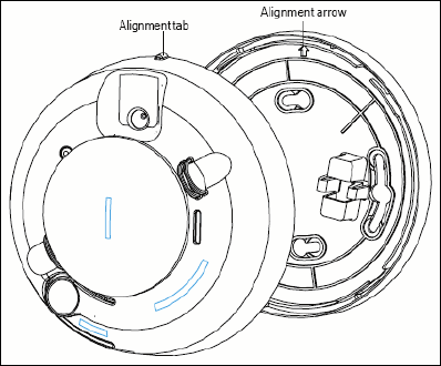
− Line up the raised alignment tab on the lip of the smoke
alarm with the arrow on the mounting base.
− Insert the smoke alarm into the base and turn clockwise
about 15 degrees until it snaps into place.
Note: The product cannot be attached to the mounting base if no
batteries are installed.
D. Test communications between the control panel and smoke alarm
again:
− Press the Test button on the alarm for 8-to-10 seconds. The
smoke alarm sends a signal to the control panel.
− Verify that the signal at the control panel was received.
E. Test the smoke alarm, see Section 7.
F. The control panel alarm and all auxiliary functions should be
verified for a complete test of the system.
UTC. All Rights Reserved. 3 P/N 0000000 – Rev. A – 06 Nov 12
4. Basic Operations
This product is equipped with an intuitive normal mode operation.
Normal Mode Operation
o In normal operation, the Status LED flashes once every 8
seconds.
o In alarm mode, the Status LED is ON – Red Color.
o In trouble or maintenance mode, the Status LED is OFF.
o In battery replacement mode, the product turns OFF the Status
LED and chirps every 45 seconds until the batteries are
replaced.
Note: the modes can be viewed from the Control Panel.
Silence the Alarm
Press the Test/Silence button to silence the sounder during an alarm.
After a few minutes, the sounder and alarm resume if smoke is still
present.
5. Installing / Replacing Battery
This product comes with two battery preinstalled. When you need to
replace the battery, use the following procedure.
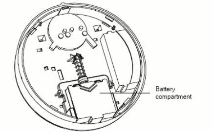
A. Slide the battery compartment cover away from the smoke alarm
to unsnap it and lift it off.
B. Observing proper polarity, insert two 3V lithium batteries into the
smoke alarm battery compartment and replace the battery
compartment cover.
C. Remove the red plastic dust cover from the smoke alarm. The
smoke alarm ships with a dust cover for protection on construction
sites with dusty environments.
Using a different battery can affect the detector operation detrimentally.
Constant exposures to high or low humidity may reduce battery life.
Replacing Batteries
Use only 3V lithium CR123A batteries, as listed on the battery
compartment cover.
A. Remove the smoke alarm from the mounting base (see “Mounting
Base Instructions” on page 7).
B. Slide the battery compartment cover away from the smoke alarm
to unsnap it and lift it off (see the figure on page 3).
C. Remove and dispose of the batteries appropriately.
D. Observe correct polarity and insert two new 3V lithium batteries
into the battery compartment and replace the cover.
Note: Use only new batteries when replacing old batteries. Do not
replace with batteries that were used previously.
E. Reattach the smoke alarm to the mounting base and test the
system.
6. Adding to the Control Panel
Each product is programmed with a unique ID when manufactured.
The unique ID is enrolled into the control panel at the time of
installation, allowing the detector to communicate with that specific
control panel.
A. Log in to the Settings app with an Installer code.
B. In the Settings menu, tap Sensors & Zones > Add a Sensor/Zone.
C. Place the smoke alarm in Search mode and prepare it to be
added to the control panel (refer to the installation documentation
for your sensors). Available sensors meet the following
requirements:
o Defaulted.
o Not currently paired with another control panel device.
o Currently in Search mode.
D. At the Locating Wireless Sensors screen, tap Next. A Done button
appears on the screen and the control panel searches for sensors
that are available to be added. As sensors are found, a grayed
icon appears for that sensor.
E. Fault each found sensor to pair it to the control panel. The icon for
each sensor is undarkened as it is faulted and the control panel
beeps. The sensor is paired to the control panel.
F. When all the sensors are found and paired, tap Stop. Any located
sensors that were not paired are released by the control panel
and can be added later. The Wireless Sensors Located screen
shows the number of wireless sensors found and paired.
G. Tap Next. The Configure Wireless Sensors screen shows icons of
the sensors that were found and paired.
H. Touch each sensor icon to configure the corresponding product.
The Add Sensor/Zone Modify screen appears.
I. To change the Smoke Icon (if multiple options are available) and
the 24-Hour Fire zone function, tap the currently selected value.
J. Tap Next. The Add Sensor/Zone Modify screen appears.
K. To modify a text field on the control panel, tap the field, use the
onscreen keyboard to enter your changes, and tap Done to save
your changes.
L. When all sensors are configured properly, tap Next in the
Configure Wireless Sensors screen.
M. If all of the sensors have not been configured, the Modify screen
appears for each sensor to let you review its details. Change the
details as needed or tap Next to cycle through all the sensors. The
sensors are marked as configured.
7. Testing the Product
This product may be tested during install or at anytime. It is
recommended the product be tested in place annually.
A. Use
Smoke! in a can
® and follow the directions on the can.
B. Hold a smoldering punk or cotton wick close to the unit and gently
direct the smoke into the smoke entry openings for 20 seconds or
until an alarm is indicated.
UTC. All Rights Reserved. 4 P/N 0000000 – Rev. A – 06 Nov 12
The LED should stay on, the sounder should emit a temporal 3 pattern,
and an alarm should be indicated at the control panel. Be sure to
extinguish the smoke source after testing!
Running the RF Communication Test
This section provides general guidelines for testing the product with the
control panel. For complete testing details, refer to the specific control
panel documentation.
o Be sure the product is normal operation.
o Set the control panel to sensor test mode to prevent an alarm
signal from being sent to the central-monitoring station if you
have a monitored system.
o To generate a test alarm, press and hold Test/Silence button for
4 seconds. An alarm message is sent to the control panel. To
generate a tamper alarm, remove the product from the
mounting plate. A tamper alarm message is sent to the control
panel.
o The control panel beeps and shows the number of RF packets
received.
o At the panel, exit sensor test mode.
8. Defaulting the Detector
This step should only be performed by a qualified service technician.
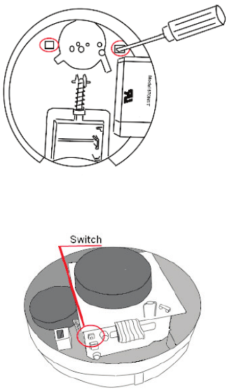
o Remove the product form the mounting plate.
o Remove the two batteries.
o Remove the product’s top cover by releasing the plastic clips
starting with the one in the battery well.
o Press the enrollment switch in the RF circuit inside the product
and hold until you replace the batteries.
o Replace the batteries while still pressing the enrollment switch
then release the switch. The RF Module LED flashes three times
to signal the detector is not paired with a control panel.
o Remove the batteries and install the top cover.
9. Viewing Zone Event History
To view event history:
A. Tap the Security widget on the Home screen.
B. Tap the History tab. The Zone Event History shows the event
history.
10. Disabling Zones
The system can bypass a zone, so the zone is not monitored when the
system is armed. This is useful when a sensor, such as a smoke alarm,
is being repaired. You can only change the Bypass state of a zone
when the system is disarmed.
The system continues to log the activity of bypassed zones in the Event
History (see “View Zone Event History,” above).
To bypass a zone:
A. With the system disarmed, tap the Security app on the Home
screen.
B. Tap the Turn Zone Off button for the smoke alarm. The Turn Zone
Off button changes to Turn Zone On.
C. When the system is disarmed, the Security Status header shows
that some zones have been bypassed.
11. Deleting the Product from the Control Panel
Deleting a sensor from the premises removes it from being monitored
by the customer’s system. This is not the same as disabling (bypassing)
a sensor. You should delete a sensor only:
o If the product is being removed from the premises
o To reset the product to factory default settings by deleting the
product and re-adding it immediately.
To delete a product from the system:
A. Contact Customer Care to obtain the Premise Passphrase for
the current customer account.
B. Perform steps A through D in Step 6, “Adding to the Control
Panel.”
C. When the Technician Settings menu appears, select Sensors
& Zones > Delete a Sensor/Zone. The Premise Passphrase
keyboard appears.
D. Enter the Premise Passphrase and click Done. The currently
installed sensors/security zones appear.
E. Tap the zone you want to delete and follow the instructions
provided by the Control Panel to delete the sensor and
security zone from the current system.
12. Maintenance
This product is design for a long service life far beyond 10-years. Even
though the control panel indicates when to service this product, several
annual and random/as required checks are recommended.
Annual - Smoke Alarm Test
Random - visual check for LED flashing every 8 seconds
- Sensitivity Test
- Wireless Signal Strength
The control panel indications are Trouble, Clean Me and Low Battery.
Trouble - the product has an internal fault, which requires
technical service.
UTC. All Rights Reserved. 5 P/N 0000000 – Rev. A – 06 Nov 12
Clean Me - the product sensitivity is out of range and requires
chamber cleaning. This may occur due to dust build up
or bug intrusion.
Low Battery - batteries are low and must be replaced to maintain
proper operation.
Smoke Alarm Test
Test the smoke alarm in place annually using Smoke! in a can®, a
canned aerosol simulated smoke and follow the directions on the can.
Sensitivity Test
This product is equipped with an internal diagnostic checking function.
The diagnostic indication via flashing LED counts, provide an overall
product operational status. After the LED flashes, if the sensitivity is
within limits and all other tests pass, the unit goes into alarm mode
and resets after 7 seconds. If the sensitivity is not within limits, or an
unserviceable hardware fault has been detected, the LED is OFF until
the product is serviced. To place the product in diagnostic mode:
A. Press the Test button on the smoke alarm for 4 seconds.
When the test starts, the smoke alarm LED flashes 1 to 9
times.
B. Count the LED flashes and see the table below to determine
the status of the smoke alarm sensitivity and any action to
take.
Flashes
Meaning
Steps to Take
1 Unserviceable
hardware fault
Reset smoke alarm and rerun
the sensitivity test. If error
persists, replace smoke alarm.
2 – 3 Smoke alarm is
becoming
insensitive
Clean smoke alarm, reset it, and
rerun the sensitivity test. If error
persists, replace smoke alarm.
4 – 7 Smoke alarm is
within normal
sensitivity range.
None
8 - 9 Smoke alarm is
becoming too
sensitive.
Verify smoke chamber is
snapped down securely. Clean
smoke alarm and replace the
smoke chamber.
Wireless Signal Strength
After adding the smoke alarm to the control panel and installing this
product, test the signal strength between the control panel and its
added sensors/security zones:
A. Be sure steps A through D in Section 6, “Adding to the Control
Panel” have been performed.
B. When the Technician Settings menu appears, select Sensors &
Zones > Sensor Diagnostics.
C. When the currently installed sensors/ security zones appear,
tap the zone you want to test for connectivity and follow the
instructions from the control panel.
The Sensor Diagnostic for <Security Zone name> appears as the
system detects the current signal strength between the selected sensor
and the control panel.
Trouble
Refer to Section 13 for trouble shooting guidance.
Clean Me
Clean the smoke alarm cover with a dry or damp (water) cloth as
needed to keep it free from dust and dirt. When necessary, use the
following procedure to clean the interior of the smoke alarm and
replace the smoke chamber.
A. Notify the Central Monitoring Station that the smoke alarm is
being tested. Be sure the system is in Test mode with the
Central Monitoring Station.
B. Remove the smoke alarm from its mounting base.
C. Remove batteries.
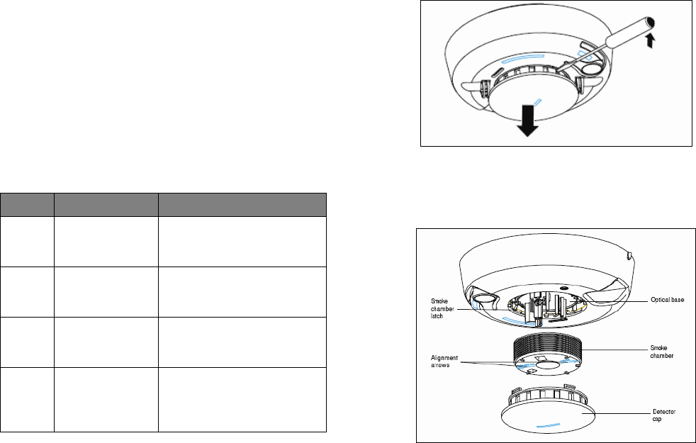
D. Slide a flat-blade screwdriver in the alarm cap slot. Gently push
the handle down to pry the cap up and off.
E. Squeeze the smoke chamber where indicated by the alignment
arrows and pull it up and away from the smoke alarm and
discard. See the following figure.
F. Blow out or use a soft-bristled brush to remove dust and dirt
from the smoke chamber base.
G. Line up the new smoke chamber with the optical base by
aligning the arrows on the smoke chamber to the latches on the
optical base and snap down into place.
H. Replace the alarm cap by lining up the cap with the smoke
alarm. Then insert the cap into the smoke alarm and turn
clockwise approximately 15 degrees. The cap snaps firmly into
place when secure.
I. Insert the batteries into the smoke alarm using the proper
polarity, and replace the battery compartment cover.
J. Reattach the smoke alarm to its mounting base (see “Error!
Reference source not found.” on this page.
K. Test the smoke alarm sensitivity and contact the Central
Monitoring Station to place the system back online (remove from
Test mode).
L. Verify all auxiliary functions for a complete test of the system.
Low Battery
Replace the batteries per Section 5 - Installing / Replacing Battery.
UTC. All Rights Reserved. 6 P/N 0000000 – Rev. A – 06 Nov 12
13. Troubleshooting
Detector does not power up properly or reports low battery
Be sure the battery is fully seated within the battery compartment and
the polarity is correct.
Check the battery voltage (3.0 VDC nominal).
Control Panel does not respond
Use a wireless RF Sniffer to confirm that the product is sending
messages for activation.
Be sure the detector is enrolled into the control panel properly.
Be sure you are using a compatible control panel.
Tamper condition does not restore
Be sure the product is installed properly onto the mounting plate and
the mounting plate has a magnet.
Be sure there are no trouble indications at the detector.
Be sure you are using a compatible control panel.
If a tamper alarm occurs
Be sure you are using a compatible control panel.
Be sure the control panel is in sensor test mode during sensor testing.
Alarm/open condition does not restore
Be sure the smoke or heat has cleared at the product.
Be sure you are using a compatible control panel.
14. Specifications
Compatible panels -
Power two CR123 battery
Battery type 3.0 VDC lithium
Panasonic® CR123A, Sanyo®123A
Standby Current
35
µ
A (typically)
Battery life 5 years (typically)
Sensor Photoelectric
Sensitivity 2.2% +/- 1.3% / ft.
Drift Compensation Adj. 0.5% / ft. max.
Heat Detection - Fixed 135°F ± 5°F (57.2°C ± 2.8°C)
Heat Rate-of-Rise
15°F/min>105°F (8.3°C/min>
40.6°C)
Audible alarm 85 dBa @ 10’ (3M) temporal 3
Low Battery Beep 1 every 45 seconds.
RF Wireless Frequency 2.4 GHz
Weight w/battery 0.20 lbs / 0.09 kg
Dimensions 5.6" x 2.4" (14.2cm x 6.1cm)
Storage temperature -4 to 140°F (-20 to 60°C)
Operating environment 40 to 100°F (4.4 to 37.8°C)
Relative Humidity 0 to 95% non-condensing
15. Regulatory Information
Manufacturer: UTC Fire & Security
WEEE Directive
2002/96/EC (WEEE directive): Products marked with this symbol cannot
be disposed of as unsorted municipal waste in the
European Union. For proper recycling, return this product to
your local supplier upon the purchase of equivalent new
equipment, or dispose of it at designated collection points.
For more information see: www.recyclethis.info.
RoHs Directive
2002/95/EC RoHS Compliant. Hereby, UTC Fire & Security declares that
this product does not contain lead, mercury, cadmium, hexavalent
chromium, polybrominated biphenyls (PBB) or polybrominated
depheny ethers (PBDE) in more than the percentage specified by EU
directive 2002/95/EC, except exemptions stated in EU directive
2002/95/EC annex.
UL Rating
ANSI/UL 217 Recognized, ANSI/UL 268 Recognized, C-UL-US, CSFM
Means of Conformity
We declare under our sole responsibility that this product is in
conformity with Directive 93/68/EEC (Marking) and Directive
89/336/EEC (EMC) based on test results using (non)-harmonized
standards in accordance with the Directives mentioned.
FCC Compliance
FCC ID: QPY-5XXNTT-Z
IC: 8303B-5XXNTT-Z
The device complies with part 15 of the FCC Rules as well as Industry
Canada Rules and Regulations license-exempt RSS standard(s).
Operation is subject to the following two conditions: (1) This device may
not cause harmful interference, and (2) this device must accept any
interference received, including interference that may cause undesired
operation.
Conformité Réglementaire
Ce dispositif est conforme à la réglementation de la IC et (Partie 15) de
la FCC. Son fonctionnement est soumis à deux conditions : (1) ce
dispositif ne doit pas causer d’interférences nuisibles, et (2) ce dispositif
doit accepter toute interférence reçue, y compris les interférences
pouvant entraîner des conditions de fonctionnement indésirables.
WARNING: Changes to Section 15 – Regulatory Information is
strictly prohibited. Any changes or modification made to the product
without the permission of the manufacturer could void the user’s
authority to use this product.
16. Product Information
Fire Prevention and Escape
The purpose of an early warning smoke alarm is to detect the presence
of fire in its early stages and sound an alarm giving the occupant(s)
time to exit the premises safely.
Avoid Fire Hazards
No detection device can protect life in all situations. Therefore,
safeguards should be taken to avoid potentially dangerous situations
as
follows:
o Do not smoke in bed.
o Do not leave children home alone.
o Never clean with flammable liquids such as gasoline.
o Properly store materials. Use general good housekeeping
techniques to keep your home neat and tidy. A cluttered
basement, attic, or other storage area is an open invitation to
fire.

UTC. All Rights Reserved. 7 P/N 0000000 – Rev. A – 06 Nov 12
o Use combustible materials and electrical appliances carefully
and only for their intended uses. Do not overload electrical
outlets
o Do not store explosive and/or fast burning materials in your
home.
o Even after proper precautions have been taken, fires can start.
Be prepared.
In Case of Fire
In the event of a fire:
o Leave immediately. Don’t stop to pack or search for valuables.
o In heavy smoke, hold your breath and stay low, crawl if
necessary. The clearest air is usually near the floor.
o If you have to go through a closed door, carefully feel the door
and door knob to see if undue heat is present. If they seem
cool, brace your foot against the bottom of the door with your
hip against the door and one hand against the top edge. Open
it slightly. If a rush of hot air is felt, slam the door quickly and
latch it. Unvented fire tends to build up considerable pressure.
Be sure all members of the household realize and understand
this danger.
o Use your neighbor’s phone or a street fire alarm box to call the
fire department. The job of extinguishing the fire should be left
to the professionals.
Be Prepared
Practice the following steps to prepare you and your family in the event
of a fire:
o Perform fire drills regularly. Use them to assure recognition of
an alarm signal.
o Draw a floor plan and show two exits from each room. It is
important that children be instructed carefully, because they
tend to hide in times of crisis.
o Establish one meeting place outside the home. Insist that
everyone meet there during an alarm. This will eliminate the
tragedy of someone reentering the house for a missing
member who is actually safe.
o If you have children and/or physically challenged people
residing in your household, use window decals to help
emergency personnel identify the sleeping quarters of these
individuals.
WARNING
Smoke Alarms CANNOT provide warnings for fires resulting from
explosions, smoking in bed or other furniture, ignition of flammable
liquids, vapors and gases, children playing with matches or lighters.
Limited Warranty
Edwards is a brand of UTC Fire & Security. The manufacturer warrants
this product (except batteries) to be free from defects in material and
workmanship under conditions of normal use for a term of 3 years
from the date of manufacture.
During the warranty period, if a UTC Fire & Security product or any of its
components becomes defective, it will be repaired or replaced without
charge.
Out-of-warranty units will be repaired at the discretion of the
manufacturer or, if not, a card will be forwarded to the customer
suggesting a replacement unit and the cost of that unit.
This warranty does not apply to units which have been subject to
abuse,
misuse, negligence or accident, or to which any modifications,
alterations or repairs have been made or attempted.
This warranty is extended only to the original purchaser of the smoke
alarm and may be enforced only by such person. During the warranty
period, if the alarm or any warranted components thereof becomes
defective, it will be replaced or repaired without charge at the
manufacturer’s discretion if returned in accordance with the following
instructions:
Obtain a Return Authorization Number by calling the number below,
then carefully pack it in a well padded and insulated carton and return,
postal charges prepaid to:
This product is manufactured by Edwards, A UTC Fire and Security
Company, 8985 Town Center Parkway, Bradenton FL 34202.
Return units to: UTC – Climate, Controls & Security
325 N Main St
Pittsfield, ME 04967
Phone: 1-207-487-3104
A note should be included advising the nature of the malfunction. Care
must be exercised in the proper packing of alarms returned under this
warranty as UTC Fire & Security will not be responsible for warranty
repairs to equipment damaged because of improper packing.
The above warranty is in lieu of all other express warranties, and
implied warranties of merchantability and fitness for a particular
purpose are limited in duration for a period of THREE years from the
date of manufacture. Under no circumstances shall manufacturer be
liable to the purchaser or any other person for incidental or
consequential damages of any nature, including without limitation
damages for personal injury or damages to property, and however
occasioned, whether alleged as resulting from breach of warranty by
manufacturer, the negligence of manufacturer or otherwise.
Manufacturer’s liability will in no event exceed the purchase price of the
product. Some states do not allow limitations on how long an implied
warranty lasts, or the exclusion or limitation of incidental or
consequential damages, so the above limitations and exclusions may
not apply to you. Unless a longer period is required by applicable law,
any action against manufacturer in
connection with this smoke alarm must be commenced within one
year after the cause of action has occurred.
No agent, employee or representative of the Manufacturer nor any
other person is authorized to modify this warranty in any respect.
Repair or replacement as stated above is the exclusive remedy of the
purchase hereunder. This warranty gives you specific legal rights and
you also have other rights which vary from state to state.
End of document