UTC Fire and Security Americas 723-TCVR SB2000 Transceiver User Manual 466156501a
UTC Fire & Security Americas Corporation, Inc. SB2000 Transceiver 466156501a
User Manual
1
ITI Part No. 60-764-01-95R
Installation Instructions
Document Number: 466-1565-01 Rev. A
June 2000
Product Summary
The SuperBus 2000 RF Receiver Module is a UL listed
device that adds or expands panel wireless zone capacity.
See the specific panel Installation Instructions for complete
UL requirements for the system you are installing.
The receiver is compatible with all ITI 319.5 MHz (crystal
and SAW) Learn Mode™ wireless sensors and touchpads,
and can be mounted inside the panel cabinet or located up to
2,800 feet away from the panel (see Table 2). It receives
information from wireless sensors and touchpads then sends
the data to the panel via the SuperBus 2000 digital data bus.
Power for the module is provided by the panel.
Receivers are available in 16-zone (-16Z), 32-zone (-32Z),
or panel maximum (-MAX) capacities.
SuperBus 2000
vs.
SuperBus
SuperBus 2000 panels have the ability to auto-address mod-
ule unit numbers. When the panel is powered up, the panel
automatically reads the unique SuperBus 2000 device ID
number and assigns a unit number to the module. This elim-
inates manually setting DIP switches and the chance of
identical unit number conflicts.
SuperBus panels communicate with SuperBus 2000
modules but require the module unit number to first be set
manually using DIP switches.
The SuperBus 2000 RF Receiver Module features:
❑Spatial diversity, which minimizes wireless signal nulls
or dead spots.
❑Compatibility with all ITI 319.5 MHz (crystal or SAW)
Learn Mode ™ wireless sensors, touchpads, and sirens.
❑Backward compatibility with SuperBus panels.
❑1,500 feet nominal, open air receiving range.
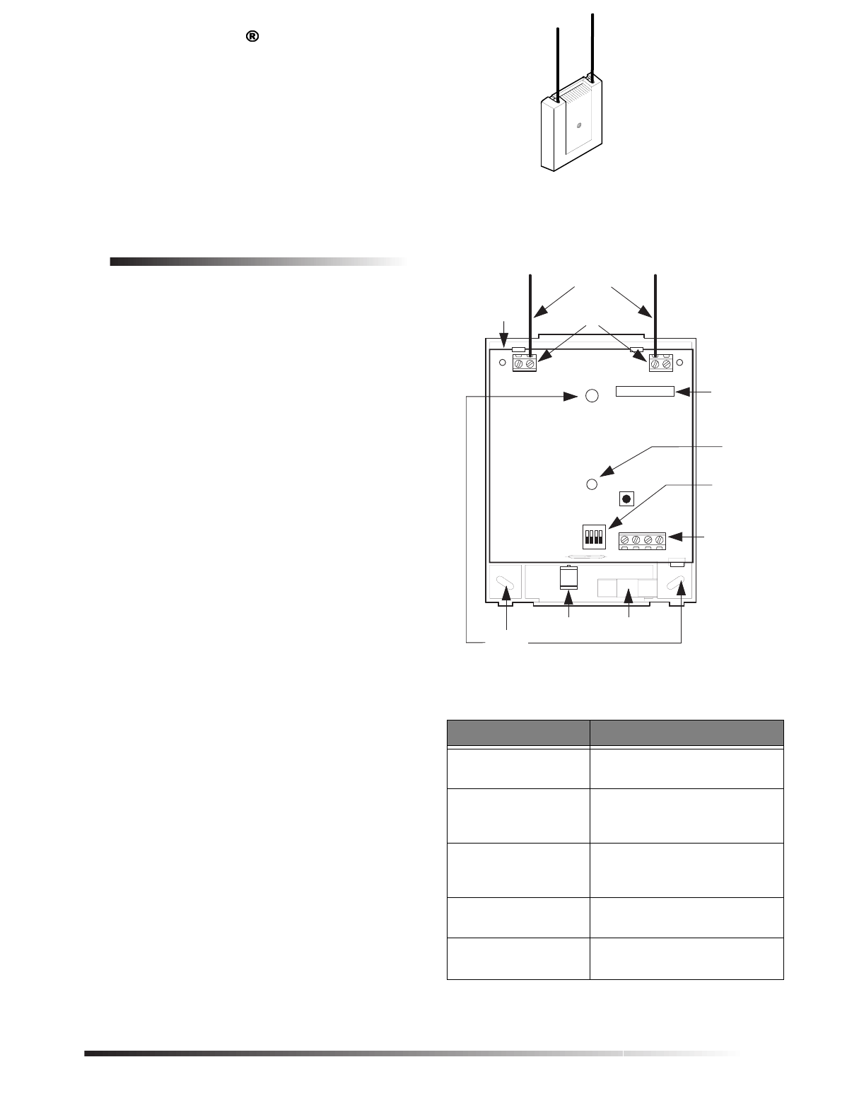
Figure 1 shows the receiver module components and Table
1 describes them.
Figure 1. RF Receiver Module Components
Table 1. Component Descriptions
Component Function
Antennas Provide communication with
wireless devices.
SuperBus 2000 Device
ID Number Label Identifies unique module
SuperBus 2000 device ID
number (SuperBus 2000 panels).
Receiver Status LED On continuously when the
receiver is powered. Flashes
when an RF signal is received.
Unit Number DIP
Switches Used for manually setting unit
numbers (SuperBus panels).
Terminal Strip Used for power and bus
connections to panel.
1065G03A.DSF
MOUNTING
HOLES (3)
CIRCUIT
BOARD ANTENNA
TERMINAL BLOCKS (2)
ANTENNAS
STATUS
LED
TERMINAL
STRIP
UNIT
NUMBER
DIP SWITCHES
ID: XXXXXXXX
SUPERBUS 2000
DEVICE ID
NUMBER LABEL
MAGNET
CLIP REED SWITCH
HOLDER
8543130A.DS4
2
Installation Guidelines
Installation Guidelines
Observe the following guidelines when installing the
receiver module:
❑Concord™ systems can accommodate a maximum of
76 wireless sensors/zones.
❑In Concord systems, up to 16 SuperBus 2000 devices
can be connected to the panel (SuperBus 2000 Touch-
pads, Receivers, HIMs, HOMs, ESMs, etc.).
❑Each bus device must have a different unit number.
❑Leave 10-inches above the module for the antennas.
❑If mounting the module inside the panel cabinet, use a
support standoff included with the Concord panel.
If mounting the module away from the panel, use the
wire length guidelines in Table 2.
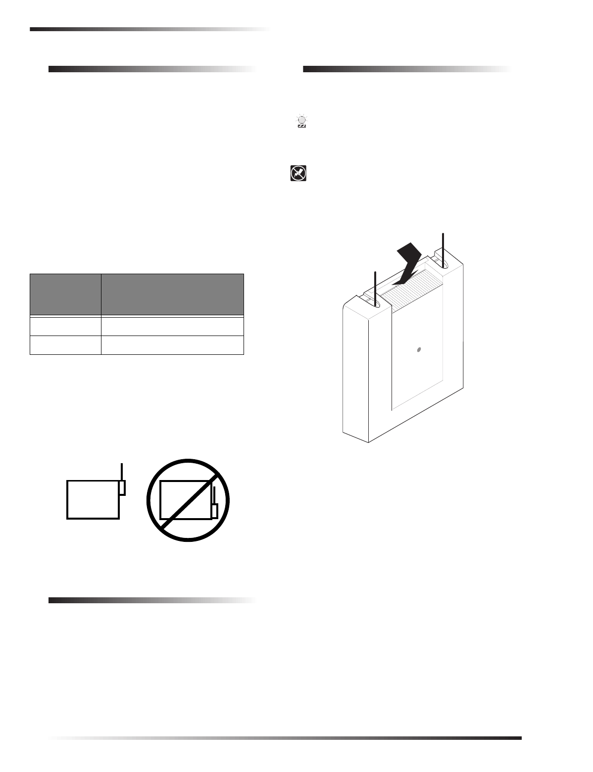
❑Avoid areas that are likely to expose the module to
moisture.
❑Avoid areas with excessive metal or electrical wiring,
including furnace and utility rooms.
If unavoidable, mount on or near metal with the anten-
nas extending above the metallic surfaces, as shown in
Figure 2.
Figure 2. Mounting on or Near Metal
Tools and Supplies
❑Screwdrivers
❑Drill with bits
❑Mounting screws and anchors (included)
❑2 antennas (included)
❑4-conductor, 22-gauge or larger, stranded wire
❑Support standoff (included with Concord cabinet)
❑¼-inch press-fit reed switch and magnet (not included)
❑Small hammer
Installation
The module can be mounted inside the panel cabinet or on
any interior wall (protected from the elements).
CAUTION
To prevent damaging the panel or module, remove the
panel AC power transformer and disconnect the
backup battery before installation.
CAUTION
You must be free of static electricity before handling
circuit boards. Wear a grounding strap or touch a bare
metal surface to discharge static electricity.
Figure 3. Removing the Cover
To mount the module on a wall:
1. Remove the panel AC power transformer and discon-
nect the backup battery.
2. Remove the module cover and set it aside (Figure 3).
3. Hold the base against the mounting surface and mark
the three mounting holes (Figure 1). Remember to
leave at least 10 inches above the base for the
antennas.
4. Drill holes and insert the appropriate anchors.
5. Secure the back-plate to the wall with included pan-
head screws.
To mount the module in a Concord panel cabinet:
1. Remove the panel AC power transformer and discon-
nect the backup battery.
2. Remove and discard the module cover (Figure 3).
Table 2. Maximum Module Wire Lengths
Wire Gauge
(Unshielded
or Shielded)
Max. Wire Length Between
Module and Concord Panel
18 2,800 feet
22 1,100 feet
METAL METAL
8836G02A.DS4
PRESS DOWN
HERE AND PULL
AWAY FROM BASE
8543118A.DSF
3
Concord Panel Wiring
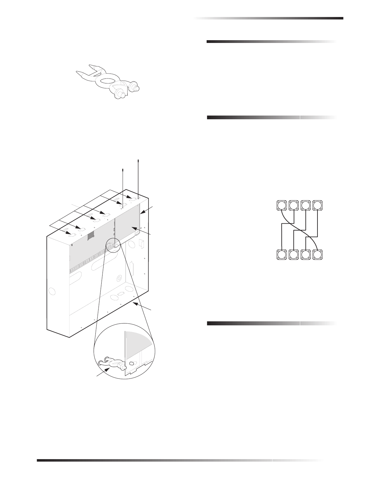
3. Insert a support standoff shown in Figure 4 (supplied
with panel) into the panel circuit board location shown
in Figure 5.
Figure 4. Support Standoff
4. Slide the module back-plate into the two top mounting
clips located on the top-right side of the cabinet and
onto the right-side support on the cabinet
(see Figure 5).
Figure 5. Mounting the module in a Concord Cabinet
5. Push the lower-left corner of the module onto the sup-
port standoff (see detail in Figure 5).
Connecting the Antennas to the Module
1. Loosen the inside terminals of the left and right
antenna terminal blocks (see Figure 1).
2. Insert an antenna into each inside terminal. (Insert
antennas through cabinet top holes when module is
mounted inside panel cabinet.)
3. Tighten the antenna terminal screws.
Concord Panel Wiring
This section describes how to wire the receiver module to
Concord panels.
To wire the receiver module to Concord panels:
1. Disconnect the panel power transformer and backup
battery.
2. Wire the module to the panel power and bus terminals
as shown in Figure 6.
Figure 6. Wiring the Receiver Module to Concord Hard-
wire and Wireless Panels
Installing an Optional Cover Tamper
Switch
If you are mounting the module in its own plastic and not
mounting it inside a cabinet, you may want to add cover
tamper detection.
To do this, install a UL listed 1/4-inch press-fit reed switch
on the module back-plate and wire the switch to any unused
panel, HIM, or SnapCard ™ zone input terminals. Once
programmed, if someone opens the module cover, the
tamper switch opens and causes an alarm.
The reed switch holder and magnet clip are located at the
bottom of the back-plate (see Figure 1 for details).
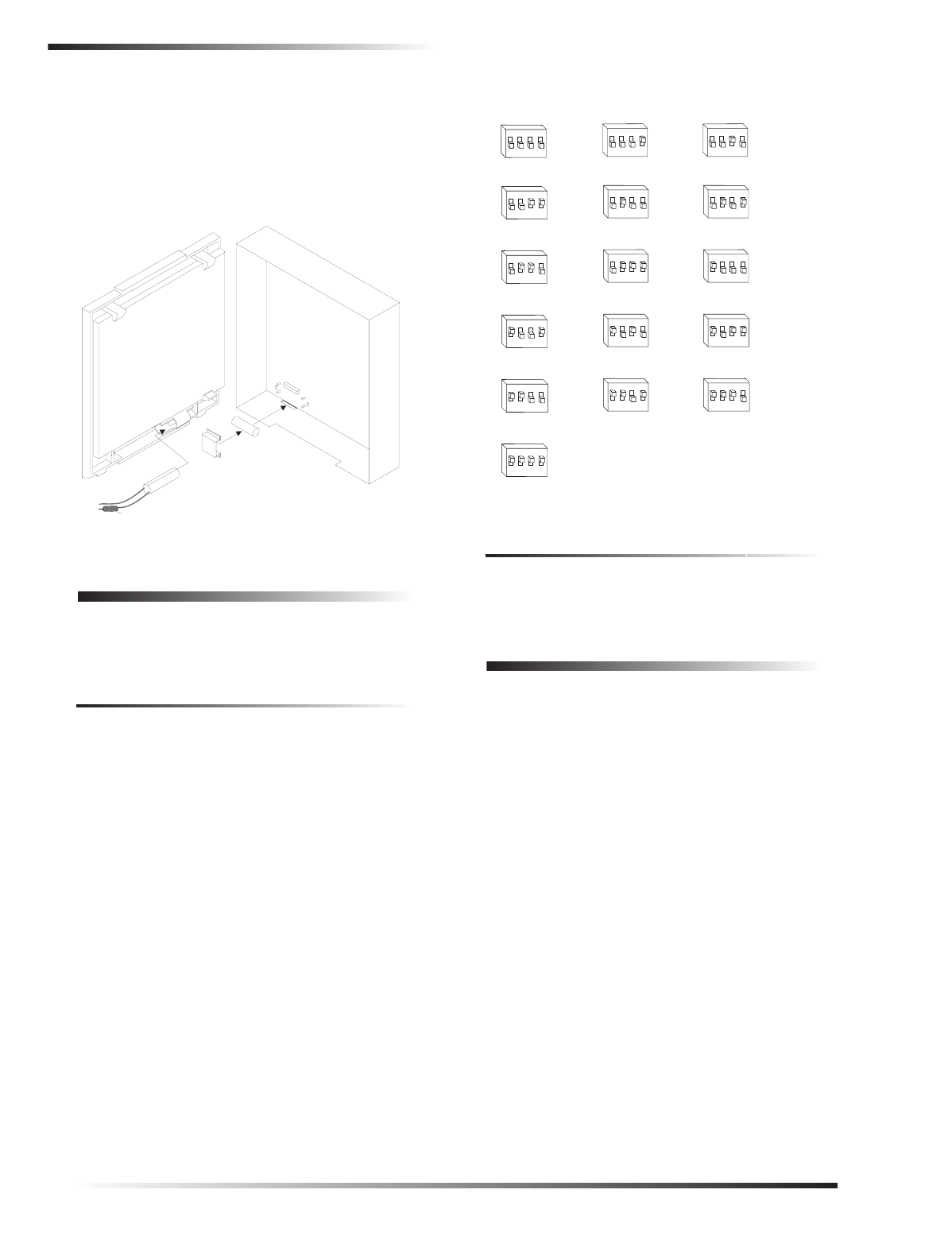
To install the tamper reed switch (Figure 7):
1. Slide the reed switch into the reed switch holder
located on the module back-plate as shown in Figure 7.
SUPPORT STANDOFF
8573
g
64A.DSF
PANEL
END
MODULE
END
8573G37B.DSF
TOP
MOUNTING
CLIPS (6)
DETAIL
SUPPORT STANDOFF
PANEL
CABINET
SIDE
MOUNTING
SUPPORT
RF
RECEIVER
MODULE
(COVER
REMOVED)
63 4 5
1065G04A.DSF
PANEL
TERMINAL STRIP
+12
VDC BUS
ABUS
B
GND
SUPERBUS 2000
RF RECEIVER MODULE
TERMINAL STRIP 41 2 3
+12
VDC BUS
ABUS
BGND
4
Setting the Unit Number
2. Insert the magnet into the nibs on the module cover.
Remove the magnet clip from the module back-plate
and press the magnet clip down over the magnet until it
clicks into place (Figure 7).
3. Connect the normally closed reed switch (in series with
a 2.0K ohm EOL resistor) to the desired panel, HIM, or
SnapCard zone input terminals. The resistor should be
located at the reed switch inside the module housing.
Figure 7. Installing the Optional Reed Switch
Setting the Unit Number
Each bus module connected to the panel must have a differ-
ent unit number set for correct communication.
Setting the Unit Number on Concord Panels with
Software Versions 1.0–1.6
The module can be set to any unit number 0–15, using the
module DIP switches.
Note
Do not set the SuperBus 2000 RF Receiver unit num-
ber to 15 if it is installed in a Concord RF system,
since the built-in receiver is factory set to unit number
15 and cannot be changed.
Locate the DIP switches on the module and set them to the
desired unit number (0–15) before applying power (see Fig-
ure 8).
Figure 8. Unit Number DIP Switch Settings
Setting the Unit Number on Concord Panels with
Software Version 2.0 or Later
The unit number will be automatically set when powering
up the system. No action is required by the installer.
Power Up and Bus Communication
Use the following procedures for powering up the system
and verifying bus communication.
Note
In order to enter panel program mode to verify unit
numbers, an alphanumeric touchpad must be con-
nected to all Concord panels.
To power up the panel and receiver module:
1. Verify that all wiring at the panel, touchpad, and
receiver is correct.
2. Connect the panel backup battery and plug in the panel
AC power transformer.
3. Verify that the receiver module status LED is on.
4. If desired, enter panel program mode to verify unit
number exists (see panel Installation Instructions for
more information).
Note
If the receiver module LED is not on, unplug the panel
AC power transformer, disconnect the backup battery,
and see Table 3 “Troubleshooting”.
9712G12A.DSF
MODULE
BACK-PLATE
MODULE
COVER
REED
SWITCH
MAGNET
CLIP
MAGNET
TO ANY ZONE
INPUT
2.0K OHM EOL
RESISTOR (49-467)
1065G05A.DSF
UNIT NUMBER 0
1234
ON
UNIT NUMBER 1
1234
ON
UNIT NUMBER 2
1234
ON
UNIT NUMBER 3
1234
ON
UNIT NUMBER 4
1234
ON
UNIT NUMBER 5
1234
ON
UNIT NUMBER 6
1234
ON
UNIT NUMBER 7
1234
ON
UNIT NUMBER 8
1234
ON
UNIT NUMBER 9
1234
ON
UNIT NUMBER 10
1234
ON
UNIT NUMBER 11
1234
ON
UNIT NUMBER 12
1234
ON
UNIT NUMBER 13
1234
ON
UNIT NUMBER 14
1234
ON
UNIT NUMBER 15--Do not use in Concord RF systems.
1234
ON

5
Programming
Changing the Receiver Module Unit Number
(software versions 1.0–1.6)
Note
Whenever the receiver module unit number is
changed, you must remove the panel AC power trans-
former and backup battery, then reconnect them for
the panel and module to communicate successfully.
Use the following guidelines when changing unit number
assignments to avoid communication conflicts between bus
devices and the panel:
❑Whenever possible, assign alphanumeric touchpad unit
numbers before all other panel programming.
❑All unit number DIP switches must be set before apply-
ing power and entering program mode.
To change the receiver module unit number:
1. Remove panel AC power transformer and backup bat-
tery.
2. Change the DIP switch setting on the module (see Fig-
ure 8). Remember, the setting must be different from all
other bus devices.
3. Connect the panel backup battery and plug in the AC
power transformer. The panel automatically scans all
bus devices and learns any new settings.
4. The system may still indicate a bus failure if the panel
learned a unit number that is no longer assigned to any
bus device. To delete the unused unit number, please
refer to the specific panel Installation Instructions.
5. Exit from program mode. The touchpad and all other
bus devices should operate correctly and any bus fail-
ures should be cleared.
Replace Module Cover/Close Cabinet
❑If you mounted the receiver module on a wall, replace
the cover.
❑If you mounted the receiver module in a cabinet, close
the cabinet door.
Programming
Refer to the panel Installation Instructions for learning
wireless devices into panel memory.
Testing
Test the receiver module at the desired location to evaluate
performance in the particular environment.
Verify that the receiver module LED flashes when wireless
devices are activated.
For complete testing procedures, refer to the panel Installa-
tion Instructions.
Troubleshooting
Table 3 describes what to do if the module does not work
correctly.
Table 3. Troubleshooting
Problem Action/Solution
The receiver module
status LED stays off. 1. Check for incorrect wiring
connections.
2. Make sure the panel AC
power transformer is
plugged in and the backup
battery is connected.
3. If the LED still remains off,
replace the module.
The receiver module
status LED stays lit but
doesn’t blink when
wireless devices are
tripped (limited or no
wireless operation).
1. Verify that the panel recog-
nizes the module by enter-
ing program mode (see
specific panel Installation
Instructions).
2. Check for incorrect wiring
connections.
3. Check receiver antenna
connections.
4. Check for receiver antenna
proximity to metal obstruc-
tions such as ducting or AC
wiring.
5. If the LED still doesn’t
flash, replace the module.
The receiver module
status LED stays lit
and blinks when
wireless devices are
tripped, but system
doesn’t respond.
Concord Panels 1.0–1.6
1. Check that no bus devices
are set to the same unit
number.
2. Change the module unit
number and re-initialize
the panel/module by dis-
connecting and reconnect-
ing panel power.
All Concord Panels
1. Make sure that the wireless
zone capabilities of the
module and panel have not
been exceeded. (Removing
one of two receiver mod-
ules connected to a panel
after wireless devices are
learned can cause this prob-
lem.)
2. If the system still doesn’t
respond, replace the mod-
ule.
6
Specifications
Specifications
Compatibility: ITI Concord panels. ITI 319.5 MHz
(crystal and SAW) Learn Mode
wireless sensors and touchpads
Wireless Zones: 60-764-01-95R-16Z
Up to 16 wireless zones
60-764-01-95R-32Z
Up to 32 wireless zones
60-764-01-95R-MAX
Maximum panel capacity
Power Required: 12 VDC nominal
30 mA maximum draw
(from panel)
Storage Temperature: -30° to 140°F (-34° to 60°C)
Operating Temperature:32° to 140°F (0° to 60°C)
Maximum Humidity: 90% relative humidity,
noncondensing
Wireless Signal Range: 1,500 feet nominal, 2,000 feet
typical open air (may vary with
application)
UL Listings (see note): UL 985 Household Fire Warning
System Units (applied for)
UL 1023 Household Burglar-Alarm
System Units (applied for)
UL 1610 Central Station Burglar-
Alarm Units (applied for)
Note
See specific panel
Installation Instructions
for
complete UL installation requirements for the system
you are installing.
Dimensions: 4.125” x 5.25” x 1.0” (L x W x H),
excluding antennas
Notices
This device complies with FCC Rules Part 15. Operation is subject to
the following two conditions:
This device may not cause harmful interference.
This device must accept any interference that may be received, includ-
ing interference that may cause undesired operation.
Changes or modifications not expressly approved by Interactive Tech-
nologies, Inc. can void the user’s authority to operate the equipment.
651-777-2690
651-779-4890
© 2000 interlogix™, inc. interlogix is a trademark of interlogix, inc.
ITI is a registered trademark of interlogix, inc. SuperBus is a registered
trademark of Interactive Technologies, Inc. Concord, Learn Mode, and
SnapCard are trademarks of Interactive Technologies, Inc.