UTC Fire and Security Americas 759-ROR Rate of Rise Sensor User Manual
UTC Fire & Security Americas Corporation, Inc. Rate of Rise Sensor
user manual
1
,QVWDOODWLRQ,QVWUXFWLRQV
*(6HFXULW\
'
Product
Summary
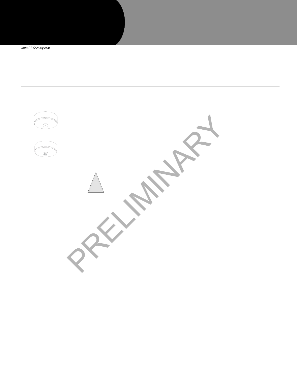
The sensors combine a Chemetron (Model 601 or 602) heat detector and a learn mode wireless
transmitter in one unit. A fixed temperature element trips the transmitter when the temperature at
the sensor location reaches about 135°F (57°C) or 200°F (94°C), depending on the model
installed.
Since many fires grow rapidly in intensity causing a rapid temperature increase, the rate of rise
element trips the transmitter if the temperature rises 15°F (8°C) or more, per minute.
A tamper switch detects when the sensor is removed from the base. The sensor then transmits a
tamper signal for the panel to receive.
All models are powered by one 3.6-volt lithium battery. When the battery voltage gets low, the
sensor transmits a low battery signal for the panel to receive.
Note
Battery life depends on how often the sensor transmits signals, but is more dependent on the temperature of
the installation environment. Batteries self-discharge more rapidly when used in high temperature environ-
ments.
SX-V® Special panels must have software version 8.0 or later installed for correct
response from Learn Mode Rate-of-Rise Heat Sensors. Do not use this sensor if the
panel uses an earlier software version. If you need assistance, call GE Security Technical
Support at 1-800-777-2624.
Equipment Needed
• Phillips and flathead screwdriver.
• Appropriate learn mode control panel/receiver installation instructions (for programming
information).
Installation Guidelines
• Heat sensors should be installed to provide property protection. Reliance should not be
placed only on heat detectors for life safety. Where life safety is involved, smoke sensors
must also be installed.
• The sensor allows for normal temperature fluctuations; however, ceiling temperatures should
not exceed 100°F (37°C) when installing 135°F models, or 150°F (66°C) when installing
200°F models.
• Mount the sensor in a central location of the area to be protected, either on the ceiling or on a
wall.
• If mounting on a ceiling, the sensor must be at least 4 inches (10 cm) away from any walls.
• If mounting on a wall, the top of the sensor must be within 4 to 6 inches (10 to 15 cm) of the
ceiling.
• The UL maximum spacing allowance of the sensor is 50’ x 50’ (15 m x 15 m). Refer to
NFPA Standard 72 for application requirements.
• Do not mount the sensor close to devices that change temperature rapidly, such as ovens, heat
vents, a furnace, or boilers.
4090G35A.DS4
60-926-01-95
135°F
200°F
60-926-95
Caution
!
'RFXPHQW1XPEHU5HY$
$SULO
/HDUQ0RGH&RPPHUFLDO5DWH
RI5LVH+HDW6HQVRUV
2Learn Mode Commercial Rate-of-Rise Heat Sensors Installation Instructions
Programming
The panel must learn the sensor ID code in order to respond to sensor signals. For complete
programming information, refer to the specific panel installation instructions.
You must be free of static electricity before handling circuit boards. Wear a
grounding strap or touch a grounded, bare metal surface to discharge static
electricity.
Static
1. Separate the sensor from the base by twisting the sensor
counter-clockwise and pulling it off the base. Set the
base aside.
2. Place the panel in program mode.
3. Proceed to the LEARN SENSORS menu.
4. When the panel prompts you for a sensor group number,
enter the fire group number (26).
5. Select the desired sensor number.
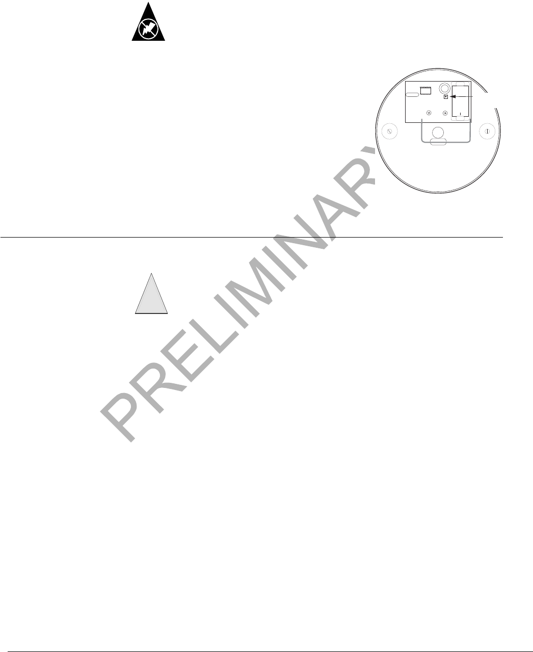
6. When the panel prompts you to trip the sensor, press and
release the tamper switch on the sensor (Figure 1). Sys-
tem sirens beep indicating successful programming.
7. Exit program mode.
Figure 1. Tamper Switch Location
Testing Before permanently securing the sensor to the wall or ceiling, test the sensor from the area it
will be located, using one of the two methods below.
The test methods described below only test rate-of-rise detection. These sensors
cannot be field-tested for their fixed temperature limits (135°F and 200°F) without
being destroyed. When used with care, the heat from a portable hair dryer
(Method 2) can be used for testing. Do not aim the hair dryer directly at the round
disc on the sensor as this can cause it to pop off. If this happens, the sensor must be
replaced.
¾Method 1:
1. Place the panel in the sensor test mode.
2. Rub your hands together vigorously, until they feel hot.
3. Place the palm of one hand on the round disc of the sensor, for about 7 to 10 seconds.
4. Listen for the appropriate number of beeps from interior sirens and speakers (refer to the
specific panel installation instructions).
5. Exit sensor test.
The sensor should reset in less than 1 minute.
¾Method 2:
1. Plug in a portable hair dryer.
2. Hold the hair dryer about 12 to 18 inches away from the sensor, aiming it at the side of
the sensor.
3. Listen for the appropriate number of beeps from interior sirens and speakers (refer to the
specific panel installation instructions).
4. Exit sensor test.
The sensor should reset in less than 1 minute.
+
Tam pe r
Switch
Caution
!

3Learn Mode Commercial Rate-of-Rise Heat Sensors Installation Instructions
Mounting the Sensor
Secure the sensor at its permanent location as follows:
1. Locate the base mounting holes (inner pair and outer pair) and mount the base to the wall or
ceiling with the appropriate hardware (see Figure 2).
Figure 2. Sensor and Base Mounting Hole Locations
2. Attach the sensor to the base.
Replacing
Batteries
When the sensor battery gets low, the sensor transmits a low battery signal. The panel receives
this signal and sounds trouble beeps through system sirens. Pressing the STATUS button identi-
fies the sensor with the low battery.
Replace the battery immediately when this condition occurs, using only Saft LS 14250 C 3.6 volt
lithium battery.
Battery Disposal
Batteries that are no longer usable are considered hazardous waste. Be sure to properly dispose of
the old batteries. Contact your local city government for hazardous waste disposal laws.
Specifications Compatibility: ............................ Commander 2000 and Custom Versions, CareTaker Plus and
Custom Versions, SX-V Special (software versions 8.0 and
later), Concord (software versions 3.0 and later), Concord
Express, Simon 2, Simon 3 (software versions 3.6 and later)
Frequency: .................................. 319.5 MHz.
Power Requirements: ................. One Saft LS 14250 C 3.6 volt lithium battery
Operating Temperature Range: .. (60-926-01-95) 40° to 100°F /4° to 37°C
(60-926-95) 32° to 150°F / 0° to 66°C
Storage Temperature: ................. (60-926-01-95) -30° to 120°F / -34° to 48°C
(60-926-95) -30° to 140°F / -34° to 60°C
Maximum Humidity: .................. 90% relative humidity, non-condensing
Dimensions: ................................ 4.40” (11.18 cm) diameter
2.20” (5.59 cm) depth
FCC Notice
This device complies with FCC Rules Part 15. Operation is subject to the following two conditions:
• This device may not cause harmful interference.
• This device must accept any interference that may be received, including interference that may cause undesired opera-
tion.
Changes or modifications not expressly approved by GE Security can void the user’s authority to operate the equipment.
FCC ID: B4Z-759-ROR
Listings
UL 985 Household Fire Warning System Units (applied for)
UL 521 Heat Detectors for Fire Protective Signalling Systems (applied for)
UL 864 Commercial Fire Warning System Units (applied for)
Sensor Mounting Holes
Base Mounting Holes
4Learn Mode Commercial Rate-of-Rise Heat Sensors Installation Instructions
©2004 GE Security. All names are trademarks of their owners.
All rights reserved.
)*(6HFXULW\